Using OpenCV with a USB Webcam on a Pi

openCV errors on the pi:

libv4l2 error allocation conversion buffer

select timeout

The title of this is constructed to (hopefully) make it easy to find this for people who are having this issue with opencv on a system with not a lot of memory.  I have moved the celery/flask code over to an actual pi, and this has caused some problems.  I have been using celery to run a little python script every minute to grab an image from a webcam, save it, and then release the webcam.

I would normally get some kind of error with libv4l2.  I have found this post very useful, and this blog entry is just to make this very valuable post more visible.  The solution seems to be to allocate more memory to the ARM processor in raspi-config memory split menu.  You can run raspi-config with:

$sudo raspi-config

This error can also be stopped by basically telling the memory management system to lie and say it always has enough memory.  This can be done with:

$sysctl vm.overcommit_memory=1

and undone with:

$sysctl vm.overcommit_memory=0

which you would want to do if you actually do run low on memory (this is all paraphrased from the link!)

Edit:

The above was helpful with the lib4l2 error but I was still getting select timeout errors when requesting frames.  This post explains how to fix it by running these bash commands:

$sudo rmmod uvcvideo

$sudo modprobe uvcvideo nodrop=1 timeout=5000 quirk=0x80

I will add more fixes if I have issues, but these links should really all be in one place.

Internet Enabled Incubator Progress

The incubator is hanging out on my floor

The incubator is hanging out on my floor

Incubators have bad UX

Springtime is here, and another ambitious biology project is in the air.  I had a lot of fun redesigning the gel box experience, and so I am going to be doing a few more biology equipment projects.  The first of which is an networked bacterial incubator.

However, is no mere incubator.  This is an incubator re-imagined to be less horrible to use.  Right now the steps to use an incubator are generally:

  1. Put plate of cells in incubator
  2. Hope that it is at the right temperature
  3. Check if colonies have grown yet
  4. Repeat until the colonies have grown, or overgrown

The problem here is that some poor soul (grad student) has to physically go to the incubator, and look at the plates and see if they are overgrown.  If you think it will take 6 hours, and you put the cells in at 6 pm on Friday, that means you have to visit at midnight on Saturday morning, probably in a deserted building.  Being in the lab alone is a bad idea.  Rinse and repeat.  That’s like going to the post office every hour or so to check if you got mail- it is a silly thing to do.  Besides being silly, there are better things to do on Friday nights.

Redesigned Experience

The main things to fix in the incubator experience are:

  • Having to go look at the cells at weird times
  • Logging temperature data
  • Logging growth data

The first point has been explained.  The last two are to add security and debug features to the incubation process.  This way you know if someone cranked up the heat, or left the door to the incubator open, and what the actual temperature is in case there is a problem.

Technical Solution

If you look at the incubator above, you will notice that it has a huge heat sink sticking out of the top.  This is because this incubator can achieve sub-ambient temperatures down to about 2C, thanks to some peltier modules.  This means you can have your cells happy and growing at full tilt at 37 C, and when you want to stop them, you can just turn the whole thing into a fridge.  This means you don’t have to harvest the cells right away- but someone still has to make the call to flip the switch.  To do this, they need a picture of the cells, and a button to press.

quick and dirty server with inputs for lighting and temperature

quick and dirty server with inputs for lighting and temperature.  Pointed at my messy desk right now

The solution of course is to make the switch-flipping and picture-viewing happen remotely, via a webpage or an app.  This is easier said than done, because of network security.  As I understand it, if I wanted to host a website on my computer or any device connected to the wireless at school, I would have to go and ask IT to set up port forwarding from our public IP address to my computer.  This would let the routers know that if someone is making an http request on port xxx, send the traffic to my computer.  IT is not likely to approve this request.

Fortunately, if you have an internet connection it is easy to “dial out”- for example, you are reading this blog right now, which is on another computer.  However, this website can’t just go around accessing files on your computer, which is a good thing for you!

The solution that seems to have taken hold is to have an intermediate platform hosted on remote server that talks to both devices.  An example of this is the spark core cloud, which seems to be used to mediate data transmission to/from sparks and computers.  I don’t like this because it adds an extra link and complexity in the connection between people and data.

The Progress So Far

Electrically and physically, the incubator works.  This is more of an exercise in hacking together a connected device, so most of the hard parts for me are code and networking related.  So far I have done a few things that I have never done before: write a server in flask-celery, template in jinja, and write an android app!  I have to say they are probably not the finest shining examples of code, but it works.

The server will be deployed on a raspberry pi that will be connected to my LAN.  The server has a page that has an up to date webcam image on it and button to refresh, and has an interface for getting data from html POST/GET to python code running on the server.  There will also be an API for talking to it from other applications.  The nice thing is that if I ever get control of my own router, I can set up port forwarding and it will be online for me to access anywhere.

One possibility is to have an android app for remotely monitoring the incubator.  It would be nice to have it on your phone or tablet for when you are out and about.  To this end I have tested an app that can post or get things from olins mobileproto twitter server.

I chose to use an http server and a pi, as opposed to maybe an arduino and a cc3000 because it gives me a little extra juice in the memory, power, and i/o departments.  In particular, it has wired ethernet, USB support, and GPIO.  This means it could be useful in other projects down the line.  Normally I go with the barebones implementation but in this case the extra power can provide something like openCV, which could be useful to process the image, and I can use a nice webcam instead of a serial camera.  Also, it can talk to other micros that might actually manage temperature control on a separate power bus.  The pi is not a RTOS, so if it gets tied up or DDOSed or something, I really don’t want it to forget that the incubator needs to be switched off- therefore some kind of micro go-between is not a bad idea.

Thing-O-Matic Design Notes

Note: This post is a bit dated since I started it in October of ’13, but as I turn to my TOM for a few more prints it is once again relevant, so I finally got some photos and posted it.

Ye Olde Thing O Matic

Ye Olde Thing O Matic, complete with cruft

If this post had a parenthetical addition to the title, it would be “(Or, how I came to loathe T-nut connections.)”.  I recently took apart the XY stage of my Thing-O-Matic to service it- I am the second owner and the original assembler had neglected to properly set the height of one of the pulleys, or possibly the pulley wiggled off the shaft.  Therefore, the belt rubbed on the platform and it had started to deteriorate.  Unfortunately, people (in particular, whoever is responsible for the TOM) have made some design errors in executing the T nut connection, and in material choice.

IMG_4888

The underside of the build platform

My biggest gripe with the T nuts on the TOM is that most of them are placed in absolutely impossible to reach places.  This machine was not designed to be serviced, ever.  some of the steps stack so that  the only way to re-assemble the machine is to completely disassemble the XY stage.  This makes it a pain to adjust or replace belts, or even to do cleaning.

IMG_4898

A properly connected t-nut connection

The biggest error Makerbot made was not lasering the holes to be clearance holes.  This means that the nuts “thread” into the wood.  They don’t really leave threads, but the connection is quite firm.  The problem here is that the extra “threads” create a constraint the bolt so that when it enters the nut, it is not free to rotate and find the start of the threads in the nut.  The nut is similarly constrained by the T slot to have to rotate in 30 degree increments.  This occasionally makes it impossible to thread the nut onto the bolt, since the bolt is threaded into the wood as well. It is very difficult to get parts to sit flush with this extra constraint.  An easy experiment to try is to hold two nuts flush with each other, with the hex faces matched up, and then try to thread a bolt through them in that configuration.  Normally, you get a few threads between them, and that distance will remain no matter how much you tighten the bolt.

Improper "set screw" configuration

Improper “set screw” configuration

This extra constraint leads to the next problem, which is the T nut as a set screw.  If you are not careful, the bolt can thread into the wood, and press the nut against the bottom of the T slot.  This creates a problem because now the bolt is actually pushing out on the wood you are trying to push in.  It can be hard to tell when this happens because of the first problem, which is that there are T nuts in deep, dark, impossible to reach recesses of the ‘bot.  And it is only a matter of time until the wood swells, or the nut rattles free, and then that T connection is no more (or more importantly, there is now a nut and bolt trying to jam your axis).

IMG_4890

On top of all this, Makerbot also ridiculously overdid things that were T slotted.  This is a 3d printer- that means there is basically no force up on the table in the Z axis (or really any force downwards, other than gravity).  The build platform is held on by no less than 8 T nuts.  These nuts are in tiny nooks and crannies.  The build platform is actually fixed not by the nuts, but by gigantic mortise and tenon joints.  MBI could have nixed most or all of the nuts in favor of letting gravity do its thing and hold the joint together, but opted for T slots upon T slots.  This introduces a manufacturing problem because it means that the holes have to be even more accurate, as the holes for the T nuts have to line up.  This is easy to achieve with laser cutting, but it is a small waste of laser time.

IMG_4886

Keerrack

My final gripe is the use of acrylic to hold up the hot end.  Acrylic is pretty tough, but the sharp stress concentrating corners on the T connections inevitably lead to cracking, which is not surprising.

I could go on and on, but much like cameras, the best 3d printer is the one you have with you!

Sketching Supply Holster

IMG_4878

Sticky tape not shown- normally I tuck it under the closure


I have started to carry a few more supplies around for better sketching, and I wanted to help prevent them from getting lost in my bag or from poking a hole in it.  The things I wanted to carry were a ruler, scissors, and double sided sticky tape.  They are quite handy for making scale drawings and adding/subtracting things from various notebooks.

I also wanted to visit a fabrication technique that I had not used in a few years: sewing.  To keep things simple, I decided to use only fabric and thread to make my holster.  No webbing, no D-rings or buckles, just fabric.  So I went out and grabbed some cheapish canvas, borrowed a sewing machine and got cracking.

IMG_4865

I started with some sketches, inspired by EMT scissor holsters.  Some of these are very elegant, in that they only use webbing folded over itself to create the pockets.  For a while, I actually used the cardboard model to carry the scissors around in.  It worked well, but it lacked pockets.

IMG_4868

Then I moved to some paper models.  One thing these did not capture was where, and in what direction seams would be.  A few of them left raw fabric edges, which are undesirable.  It might work with webbing, but not with the canvas I had- it would unravel.

IMG_4870

After some sewing I figured out how to make straps where all the edges were internal.  I would have preferred to sew a long tube and flip it inside out, but the aspect ratio was not condusive to this.  Notice the extra reinforcement on the bottom of the rightmost prototype.  This was added to prevent the potentially pointy scissors from puncturing the bag.  You can see it on the final prototype in the top picture, under the large X.

Final model, showing pockets for scissors and ruler

Final model, showing pockets for scissors and ruler

Here is the final model.  It handily holds everything together in my bag so I have it on hand when I need it.  So far it has preformed quite well.  As a bonus, it is red so it is easy to find on the train or buried in my bag.

AE-1 Camera Battery Adapter

exploded view of a similar Canon film camera from sao pao camera style blog

I have this film camera that I think is pretty cool.  It definitely has a brighter, larger viewfinder than my sl1/100D, which I admire for different reasons.  Unfortunately, I took it out in the rain a few months ago, and it stopped working.  I was pretty sure it was because the battery had shorted out, because most of the very basic electronics in this camera are hidden under the heavily chromed plastic exterior.  I also noticed that the shutter, which has an electronic release, would not work.  Despite all the giant fingers pointing to the battery being the issue, I didn’t order batteries because fixing the camera was a low priority, because getting film developed is such a tedious process around here (frustrations include: processing machines often down, sending film out and waiting for a CD to come in the mail).

Battery adaptor

Battery adapter

Flashforward a to a week ago when I bought a bunch of lr44 batteries to go in my digital calipers/DRO and I suddenly realized that with a simple adapter, I could get my camera tested.  I ended up jamming a scrap 1/2″ diameter piece of aluminum under four of the 1.5 v cells to make a 6V battery.  The camera instantly came back to life!  After that I turned down a classier adapter on a lathe, and finally broke down and ordered proper batteries.  I went out and shot a couple rolls of film after that, and when I went to get them processed, the machine was (inevitably) down.  So someday, I might find out if the light meter needs tweaking, but for now at least, it seems like the camera works.

Allison Mine Day Trip

28-IMG_2792

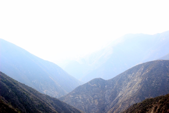
Swan rock and surrounding mountains from the ascent to the mine

This hike is not for people who are claustrophobic, acrophobic, or who are not in tip-top shape, but I went anyways.  That being said, it is a long, hazardous and very rewarding adventure.

After being thwarted by Stanley Miller on two separate occasions (for various reasons), my brother and I decided to test our luck on the closer and seemingly easier to reach the 100 year old site (just last year year!) of the Allison mine.  This mine made the late Hugh Blanchards list of “Local Gold Mines We Will Never See!”, which only made it more appealing.  Hugh Blanchard lists it as a 14 mile hike with 3000 ft of elevation gain, but we clocked in at 10 miles with ~2400 ft of elevation gain.
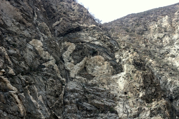
04-IMG_2634

Swan Rock

The most direct route starts at the Henniger flats parking lot.  After departing from the trailhead, you head upstream making a few river crossings, which should all be pretty easy.  All the crossings have some kind of feature (log, rocks) to assist in crossing.  At no point should you have to step in the water!  The same goes if you are heading to the bridge to nowhere.  At some point, you should see swan rock (pictured above) as the river makes a left turn (relative to heading upriver, a right turn if you are headed down).  It is my belief that the part that looks like a “swan” is that white part in the middle of the rock.  It is also important to mention the scale and location- it is a massive, nearly vertical cliff face, not a huge boulder.

16-IMG_2724

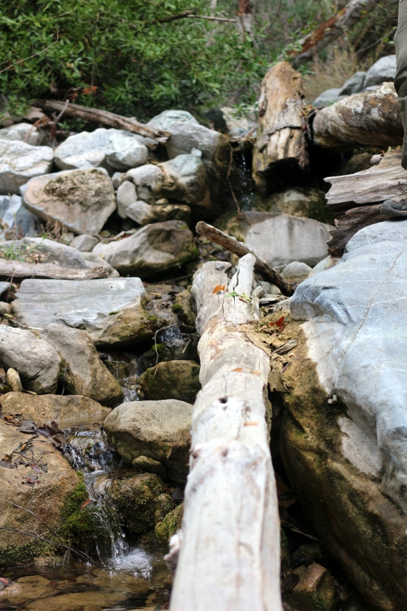
Water in Allison Gulch

A fraction of a mile upriver is the entrance to Allison Gulch, and where you start to take the trail off the (literally) beaten path of the east fork.  Its most defining feature is that there is some kind of concrete drainage ditch there.  The gulch itself is actually quite pleasant during the day.  The white rocks are set off by deep piles of red leaves and the steep sides and foliage provide good sun protection.  We brought a water filter with us so that we could stock up on water when it was available.  This was a good idea, because we didn’t have to carry all our water with us all the time.  Fortunately for us, we found plenty of water in the gulch- at the bottom, at the point where we ascended, and finally at the mine, so we never had to worry about running out of water, although we were conservative on the way up.

31-IMG_2799

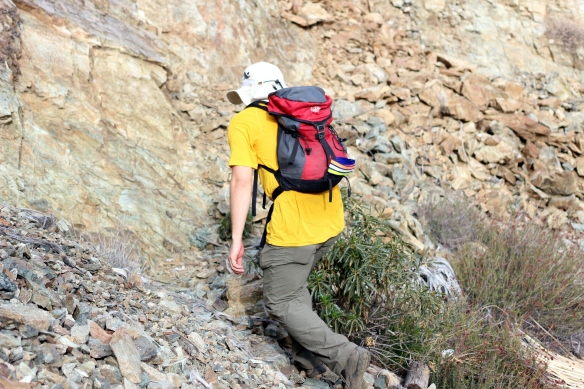
#2, my brother, on the so-called “path” to Allison mine

A mile or so upstream of the entrance to the gulch there are conspicuous markers that lead to the trailhead, which include but are not limited to a pair of boots on some small trees, a rusting shovelhead, and a jacket that is stiff from exposure.  This marks the beginning of about 2000′ of elevation gain over about .4 miles (walked distance), on a sun-drenched and steep trail, mostly made of dirt but including occasional piles of scree.  If it had been hot, I think we would have turned back!  As it was, we took frequent breaks and ate lots of snacks.

33-IMG_2806
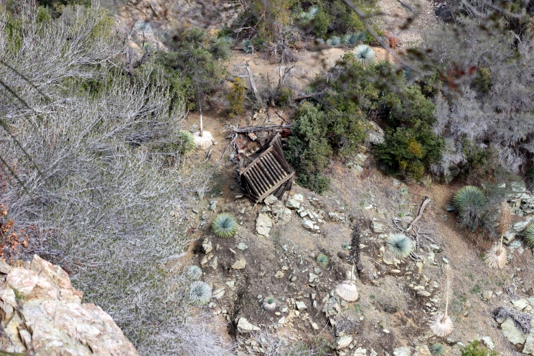
At the apex of our ascent, the path took a sharp turn to the right and followed a contour line back towards the gulch.  The reason the path was created becomes apparent when you realize that the canyon, for all intents and purposes, ends in a sheer drop not far from the mine, making it impossible (or at least, improbable) to navigate to the mine via the floor of the gulch.  As we got closer to the mine, we saw one of the few structures left standing- an ore hopper.

55-IMG_3014
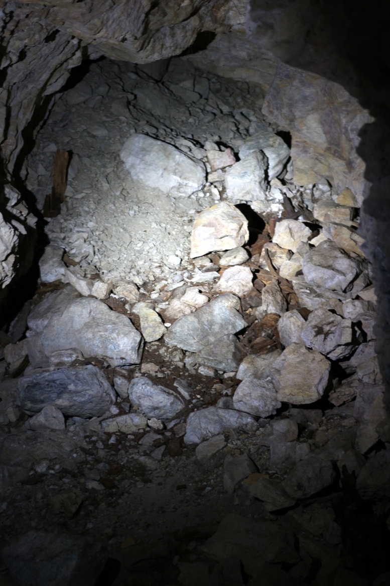
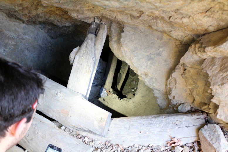
At the site of the mine we discovered three entrances which we explored (two of which connected).  One was practically paved with cans at the entrance, and featured many branches, one of which ended in a cave in.  The other digging featured two entrances and many vertical shafts which we did not have the time, people, or equipment to explore, although we did photograph them.  At the upper entrance to this digging we found what appear to be even more tunnels, although we were running out of time to explore them.

39-IMG_2879We also noticed the remains of a camp site up around the mine.  The equiptment looked disturbingly modern, but it had clearly been there for some time as the tent had been blown around and the sleeping bags had been sun-bleached- we wondered where the people were, and we hoped the answer was not that they were in the collapsed section of tunnel.  In another part of the enormous mine site, we found a cache of what appears to be a sleeping bag or pad and a tarp, as well as some 5 gallon buckets.  These were in a well-protected area, so they may be the same vintage as the tent, but it is hard to tell because they are not weathered.

84-IMG_3212
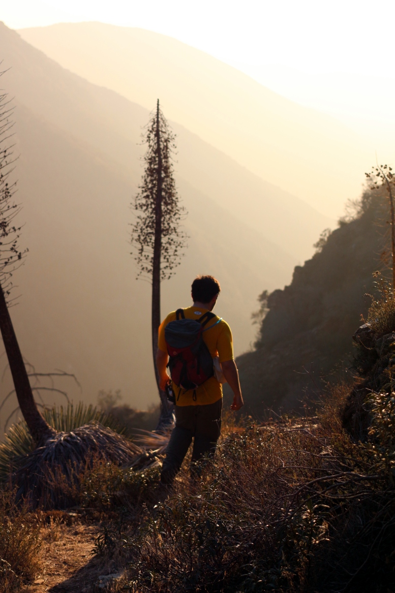
By the time we had filtered more water and made our departure from the mine site, we knew we wouldn’t make it back without some night hiking.  As the last rays of the sun diffused through the hazy canyon, coating everything in a golden glow, we were working as fast as possible to get off the mountain.  At one point, we got off the trail, which was a costly mistake- it is considerably more difficult to get down in one piece where there is not a trail, and there are many small paths that look like trails.

95-IMG_3281
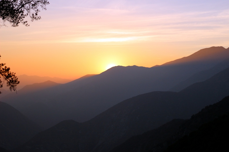
This is basically the last we saw of the sun.  While it was an amazing view, it meant that by the time we hit the floor of the narrow and overgrown gulch, it was very dark.  Our headlamps came out again and we made our way down the gulch, this time picking up on an actual trail and saving lots of time.  By the time we made it back to the trail we were sweaty and sore from pounding our joints on the steep decent.  By the light of our headlamps, we started our hasty retreat to the parking lot.

But the adventure was not over yet!  On our way back we found a couple of people and a couple of dogs (two of each!  a couple of couples) trying to navigate their way back to the parking lot without any kind of light (save the moon, which was about 3/4 full).  We shared our light and escorted them back to the parking lot, over quite a few steep rock steps and river crossings.

GelIS Production Pt 2: Laser Cutting Time!

parts for future gel boxes!

parts for future gel boxes!

Today I hauled about 10 pounds of assorted acrylic 15 miles into the city of Cambridge and back to where I live.  The journey took about about 7 hours, and about four hours were spent laser cutting!  Of course, that is operator time, not tool time.  Since I am cutting, the big factors to control are material usage and tool time.  I cut the boxes at danger awesome, which charges $2/laser minute, meaning if you cut for 5 minutes, you are charged $10.

This makes part packing really, really important.  Part packing is the positioning of each part on the sheet that it will be made of.  Like many spatial challenges (routing PCBs, putting linkages on different planes, etc.) in engineering, there are probably tools for this, but there is certainly a sense of satisfaction in using your very own brain to solve the problem.  While the box was designed with fabrication in mind, I hit some speed bumps during cutting and learned a lot.

cutsheets

Black edge- 12 x 12 rectangle
Red edge- actual sheet
Green edge- parts I made

The first problem was that the parts I wanted to cut were 6×5 inches and would barely barley fit on a 12×12 sheet (as seen on the right).  I am pretty careful, and given a few thou over 12″, I was pretty sure I could cut out parts per sheet, like on the right- but the sheet was smaller by 1/8-1/4″ on each side!  So I went ahead and re-arranged the cusheet in coreldraw into a pinwheel shape (strangely, corel is much better than solidworks for this), and I ended up with excellent results, as seen below!

IMG_2122

The nice thing about packing parts like this is you get to share edges, which is basically 50% off the cut time for that edge, plus you save on material between parts and have a lower chance of melting or warping parts with nearby cuts.

IMG_2121

One of the nice things about the gel box is that most of the parts have similar-sized notches cut in them for mortise joints.  By keeping these the same throughout the box, the parts are easier to arrange, and they can share cuts!  A tip here is to make groupings of parts, and arrange them (sharing edges) into mega-parts that have edges that are easy to share with other mega-parts.  That is how i ended up with these cutouts being so clean.  You can see on the bottom two cutouts that the parts were mirrored across a horizontal line, and on the top the parts were pinwheeled again.

This might be it for the notes on making the gel system- I could write about boxing it all up, but I haven’t discovered a good way to do that except to do it while drinking a hot beverage or while watching a movie.

GelIS Production Pt 1: Lead Times

DC-DC converter, the heart of the Gel Power Supply

DC-DC converter, the heart of the Gel Power Supply

Sourcing this part is critical to being able to continue to sell GelIS.  Unfortunately there is an incredibly long lead time on these parts, as they come from China.  My strategy is to generate a few orders for the box, and then order extras far far in advance.  I hope it works!  If the rate of orders keeps up, I should be ok, but otherwise delays could happen!  I will have to think carefully about this.

Gelis: Final Cut

GelIS- Final Prototype

GelIS- Final Prototype

The Gel Integrated System is done.  I have packed an electrophoresis power supply, illumination, and casting system into one tiny box.  All the parts, other than the enclosure, are off the shelf parts.  It can be shipped flat and assembled with only a screwdriver.  This all comes in at a sale price that is an order of magnitude lower than commercial systems, with a bench footprint an order of magnitude lower than commercial systems.

Test Run

Test Run

It has been tested, and it is completely functional.  The gel is bright enough that you can take pictures of it with your cell phone.  If you want to get one, I will be selling the first batch of ten here for $200 a piece.  Use that link to contact me if you need a large batch, or find me on the diybio mailing list.  I will hopefully have an assembly video (and feature video) soon, but until now you can see my instructable on assembly here.

GelIS Simplified

The latest GelIS prototype

The latest GelIS prototype

Almost ready to test the latest prototype!  Everything electrical is go, but I managed to loose my LED panel in my moves from showing my prototype in CA, visiting the bay area, and them moving from an apartment in Somerville back to school.  Oops.

IMG_1401

One of the major improvements in this prototype is simplified wiring.  I did away with the ammeter (since it was on the fritz anyways), and now it is very easy to assemble with only a screwdriver.  The improvement is that lots of wires don’t need to go into screw terminals now- there is a max of only two wires per terminal, and if you wrap stranded wires around solid wires, you have a pretty solid connection.

I am really looking forward into getting these into peoples hands!