The PCB heater for the hotplate obviously needs to be driven by something. I could have put more circuits on the heater board itself, but separating them has some advantages:
- if the heater element is bad, or needs reconfiguration, it can be replaced
- better opportunity for a heat break between the boards
- opportunity to try different heater substrates or even different heaters/heater shapes
My goal for the hotplate is to keep it simple. I decided that I really probably need one profile at most, and a manual-temperature mode. I’d rather make that profile on the computer, instead of on the device, and be able to play it back from the device. I’d also rather get information back from the plate on the computer instead of a tiny display. Hopefully these simplifications will allow a hotplate to be up and running sooner rather than later.
Here is the architecture I came up with:

There are two usb C connections- one for programming the micro, and one for power, equipped with a USB PD “trigger” chip. My new favorite controller, the ESP32-C3 is in charge of the show (and native USB C). A single thermocouple is used for feedback, and an RTD is used as a safety cutoff- basically if it goes above some target temperature, the micro will no longer be able to drive the power FET. This won’t prevent the board from getting super hot, but it does provide a hardware safety against exceeding some set temperature if the controller spaces out…assuming the thermistor does not fall off.
Additionally there are indicators for PD power, DATA power, data transmission (heartbeat), heater power, and safety over temp, hot surface, mode, and (finally) a temperature readout. These are diagnostically useful, and they should satisfy my desire for a cool looking annunciator panel.
One annoying thing is that the ESP needs to be driven at 3v3 while the rest of the stuff is happy at 20V. While a cheap, integrated buck would be a neat solution, an LDO is so much cheaper. I decided to go with the buck, since I wanted to avoid burning extra power when operating near the 100W limit of the power supply.
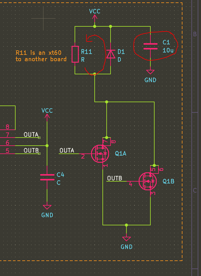
The heater itself will be driven by a gate driver like the NCP81071B, which is 20V tolerant. 20V will just barely allow us to use something like the AOSD32334C, which is a dual N FET. Paralleling the FETS will reduce the RDSon to almost nothing- close to 10 mOhms.
The heater element here is represented by a resistor and an inductor- I expect the trace to have some very real inductance (100s of nH?), which will cause a large voltage spike when the FET turns off. This could easily exceed the 30VDS of the FET, and cause it to break down. The flyback diode will hopefully prevent this. Additionally, a capacitor Cbulk will be chosen to prevent over-drawing current from the power supply. At 20V, the 3.3 ohm heater will draw 6A, while the maximum allowed current is 5A. By PWMing this, the average current will be below or at 5A, but when the heater is on that current needs to come from somewhere- the bulk capacitance C.
To connect to the heater itself, I am using an XT60 connector. These are low-resistance and they seem easy to get, due to their use in drones.
Safety + Temperature Monitoring
There are a lot of ways making a big heater that is capable of destroying itself can go wrong. Ultimately this device falls under the category of things you should unplug if its not in use, and definitely not something to leave running unattended. However there are a few details I added as a nod to safety.
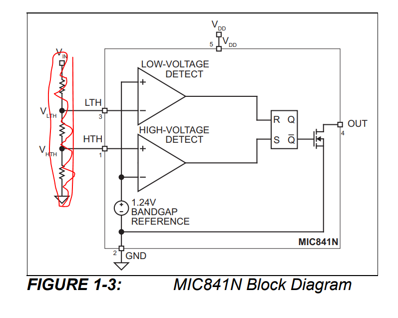
The first is a thermal trip based on the MIC841N The HTH input is fed by a NTC resistor divider that exceeds the 1.24V reference at about 200C. This SETs the latch, so the inverting output goes low, pulling down the enable pin of the fet driver. This is the case until either the whole circuit is reset (and the thermistor has cooled off) or until the reset line is pulled down by a button. Resetting while hot should result in an illegal state where ~Q is still 0.
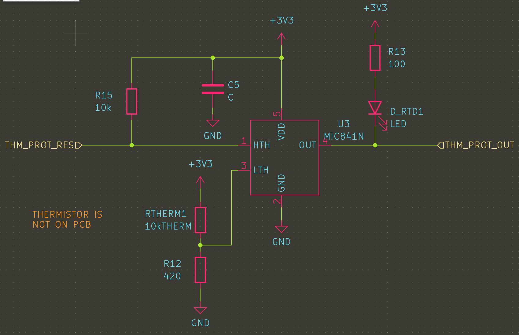
Note: this circuit totally fails if Rtherm is removed, and it wont work if Rtherm gets disconnected from “the hot part”. If I wanted to add more logic, this could be resolved, e.g. inverting the logic of the resistor bridge. However, this is currently just a secondary protection. If it works nicely it can be refined later.
Temperature monitoring (for feedback and control) will be done with a thermistor dropped either onto the heater, or onto the target PCB. This allows for point control, near the stuff that you care about. For the time being, this will be made out of a MAX31850 thermocouple breakout that I have lying around from years ago.
Next Steps
With the heater and the controller designed, its time to get them made and then patiently wait for them to arrive!
