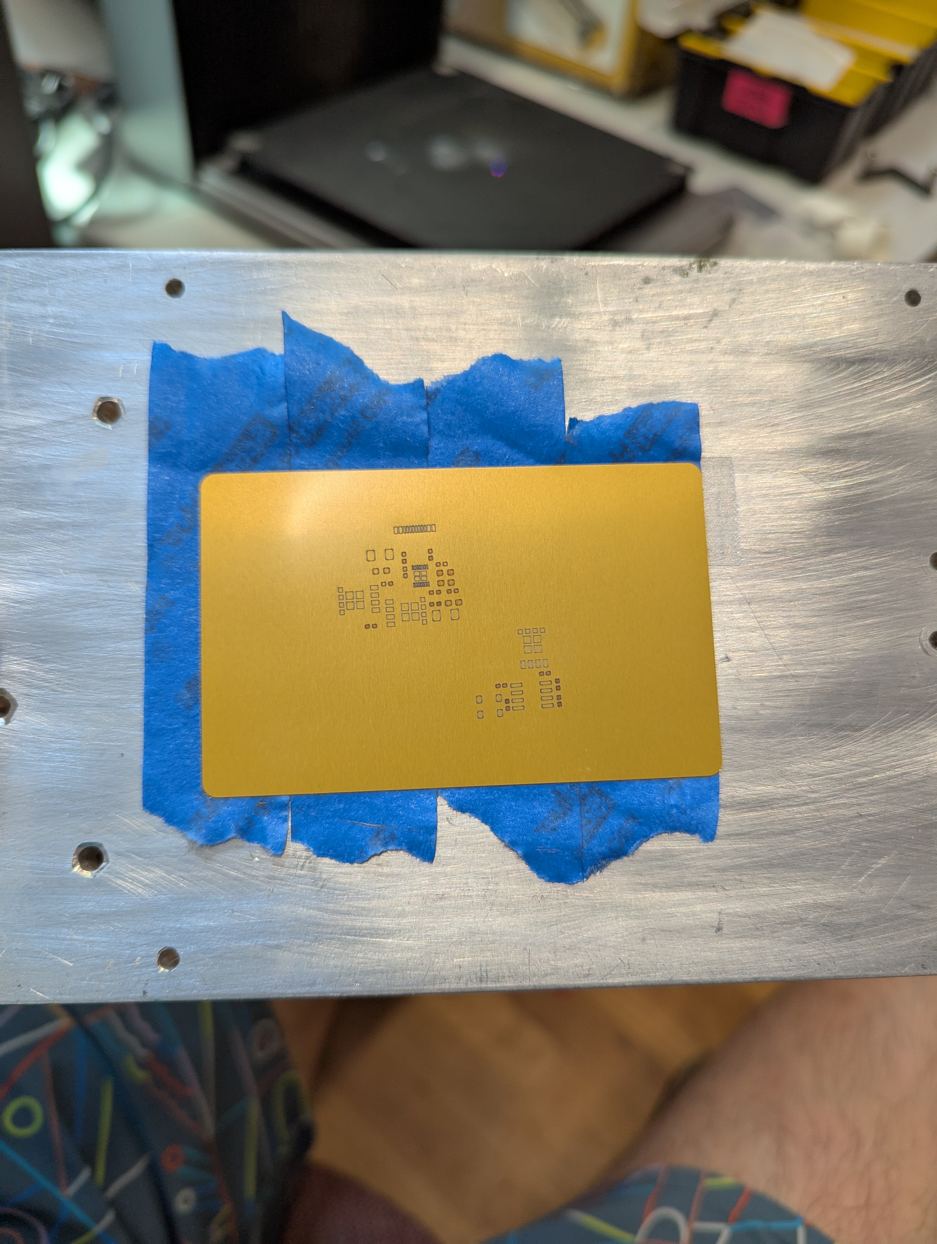
After my initial success with cutting metal stencils on the xtool F1 ultra, I realized that the re-ordering and careful setup of the stencil by hand would really put a damper on my stencil making enthusiasm. Having to re-order hundreds of vector paths by hand is time consuming, and its not easy to visualize and certainly difficult to optimize. Fortunately, this is a fairly straightforward problem of ingesting a file, doing some algorithmic stuff to it, and looking at the output. The perfect kind of problem to take on with my new pal, Claude.
What StenciLaser does:
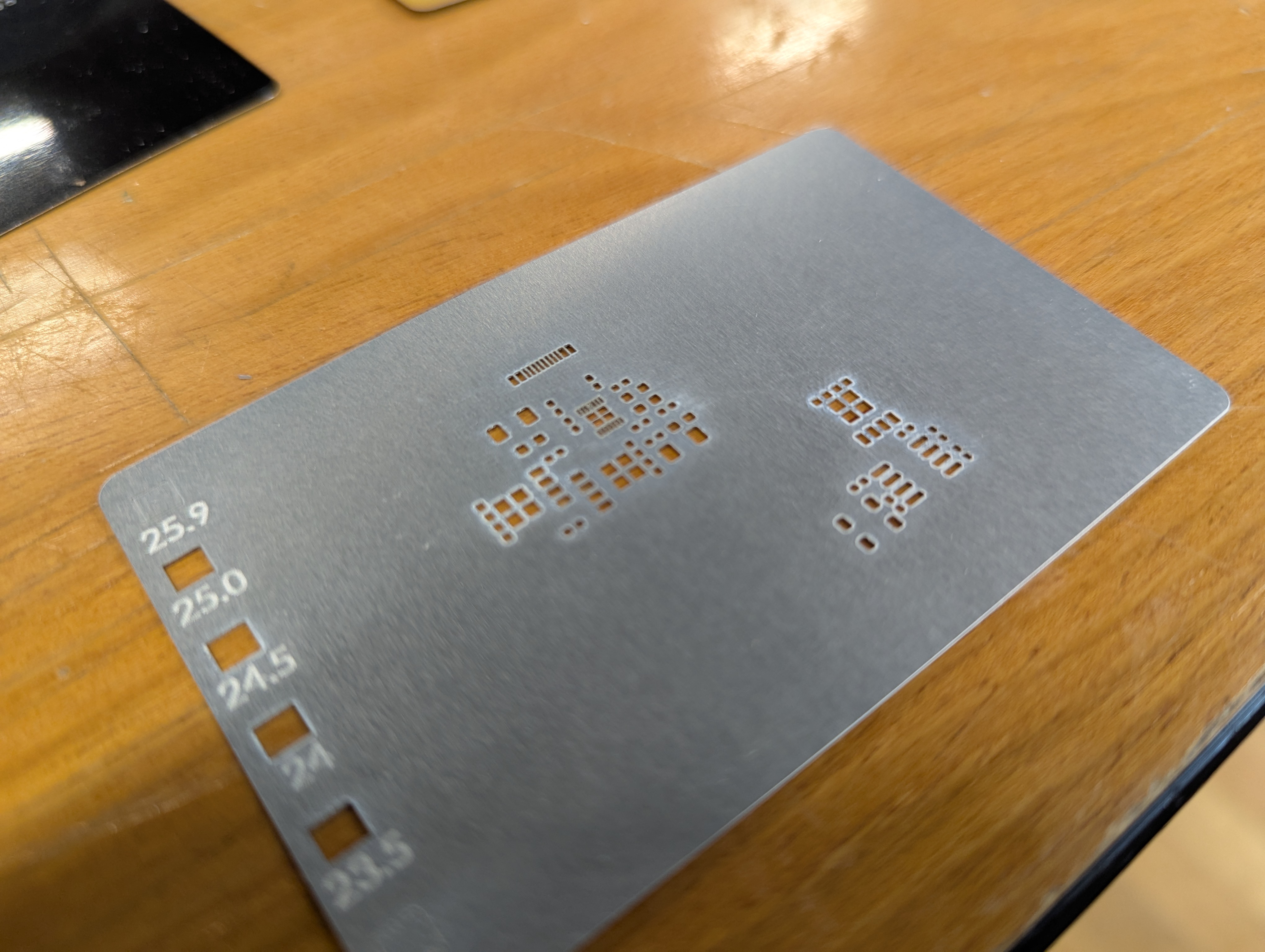
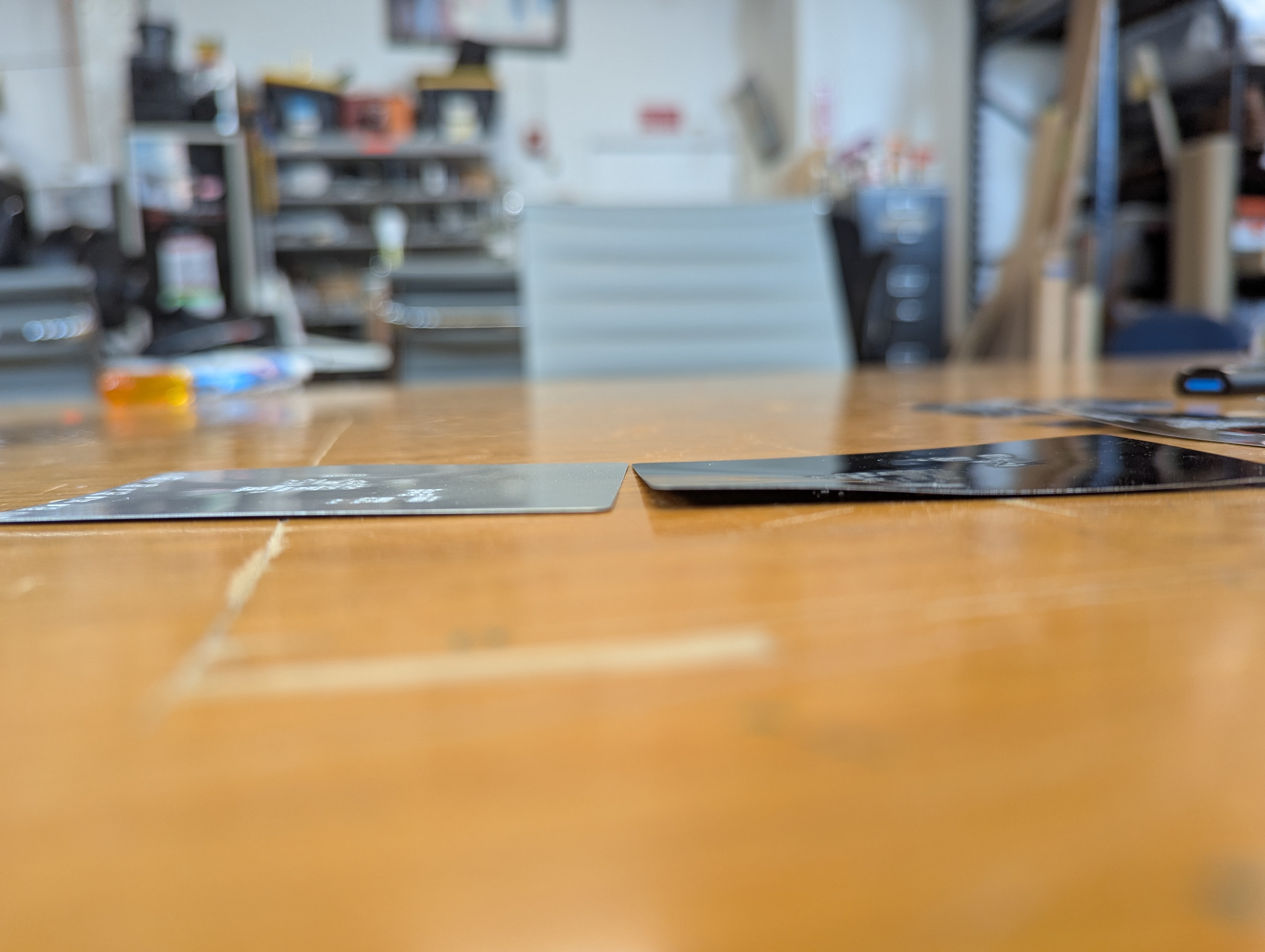
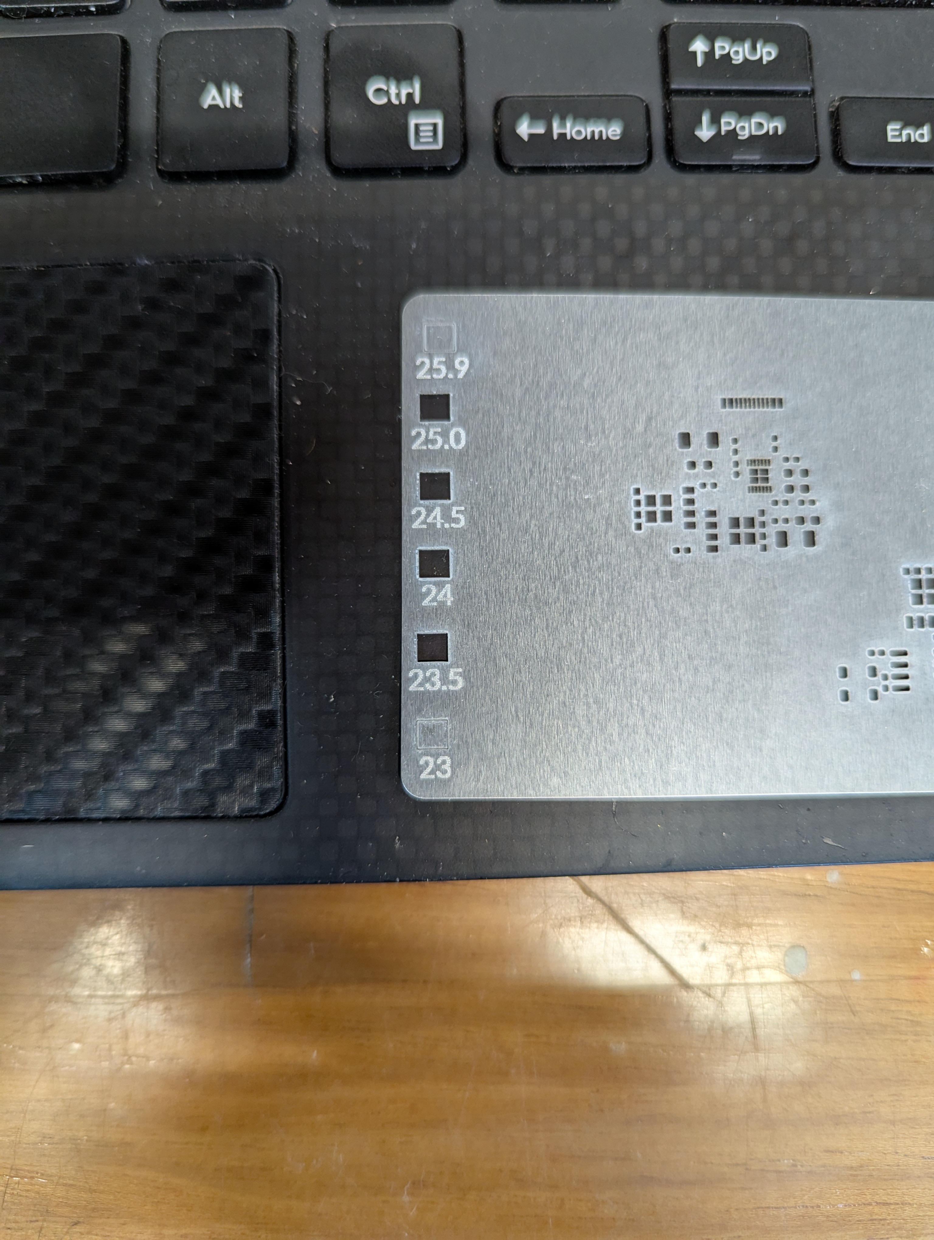
StenciLaser is a program that takes a DXF and creates an .xs or .xcs file for the F1 ultra where the cuts are ordered to minimize heat affected zones and warping. These thermal effects happen when the laser focuses a lot in one area. For thick substrates, its not as much of an issue since stress will just build up in the part, and be relieved later when it cools. However, with thin parts, the heat is enough to cause permeant deformation of the the part.
To avoid cutting a lot in one place, we need each cut individual cut not to warp the material, and then cuts also need to be spread out as much as possible. I can’t claim that the approach I took will never warp a stencil, but its pretty good. StenciLaser takes all the apertures and breaks them into groups of equal quantity, then goes round robin around the groups and chooses one aperture to cut. The chosen aperture is the furthest from the last cut, and is weighted to also avoid the last cut inside the group. The round robin chooses the furthest group from the last cut.
Finally, the program packages it all up into an .xc or .xcs file. One thing that seems to work, but that is not officially supported is infinite layers. This is important because the only way to get the xtool studio to respect the cut order is to go to processing->cut order->by layer. With only 16 layers (the default) xtool studio will not fully respect the optimized cut ordering, which is a big problem.
Issues+Future work
One issue with this program, possibly due to the infinite number of layers, is that processing in xtool studio takes a long time, especially with many repeats. I found it easier to set repeats to 10-50 and just press the button multiple times rather than wait forever for the processing to be done. This step can take several minutes, but since it happens in the xtool code I can only guess why it takes so long. Possibly it struggles with so many layers, or maybe the number or unique cuts and “travel moves”.
The algorithm is also not perfect. There are some trivial degenerate cases where it might produce bad output, like a very dense grid of rectangles, or having very few cuts to do that are close together. One issue is that the algo is “greedy” and might run out of good candidates while maximizing distance in round robin, instead of maximizing average distance. So far the greedy distance algo seems to be ok in most cases, but it could be an improvement to change to maximizing average distance.
The other issue is that there is no way for the program to “pause” right now. So if there are two rectangles right next to each other, they will just get cut one after another, even though it will cause a lot of local heat. There could be a solution to this too- even though there is no “pause” to put in, a large path at a low speed/intensity could be drawn to waste time. However, this hasn’t been an issue since usually a stencil has a lot of cuts in it.
There are cool improvements to be made too! For example, laser cutting stencils can leave burrs for a couple reasons- either from melt-freeze or from “tabs” that get broken either from heating/cooling and expansion/contraction, or from later manual removal. It would be interesting to add a deburring or even an aperture (vertical) keystoning pass similar to the “aperture enhancement” that is sometimes offered on commercial stencils.
How to get and use StencilLaser
Go here: https://github.com/Aylo6061/StenciLaser. There are instructions for use there. Be sure to set cut order->by layer in the processing menu of xtool studio! or it won’t work.
What I think about Claude Code
This is the kind of problem that in the past, would have required a lot of work on my part that I have historically not been great at, or very interested in – setting up a GUI, making sure the data stays synced with the gui, making sure buttons are the styled right, making sure dividers and cells resize nicely etc. In this case I was able to get a tested prototype done in an afternoon, which is incredible. It even has an ok installer, which should make it easy for me to share this, and which is something I would have avoided making in the past.
There are many complaints about various AI programming tools, but I’ve been overwhelmingly impressed. I think this technology will really let people write super niche software, to solve really specific problems for specific users way faster than anything else ever has. More importantly, I’ve taught a few non-technical people to vibe code, and they have been able to develop software for their own problems. It will be exciting (and scary for some people, like IT admins) to see what people do with this new tool.