I have started seeing a whole bunch of PCB hot plate builds, of varying success. I kind of want one now, since they seem very practical for one-off small PCBs, and most off the shelf solutions are quite large. However, I also want to improve on the state of the art of PCB heaters. These are useful for all kinds of stuff, from PCR machines to 3d printer hot plates.
Builds I researched:
CarlBujejas V1/V2 hotplate videos, files
AfterEarthLTD Solder-Reflow-Plate git, video coverage
electronoobs video
There are a lot of challenges to overcome to make something that does not suck. Ideally, it could even be USB powered. Below are some calculations and considerations for making a pcb hot plate. You can see the WIP (scripts, pcbs, etc) on github.
PCBs are not a good material:
Using a PCB as a heater is not a new idea- however, in some ways, they are not good material candidates for high soldering temperatures:
- The board will be at/above TG for a long time
- solder mask/silk can discolor
- could de-solder itself/the controller
- repeated stress on copper tracks from board warping while heating
That said, several people have made them and they seem super-good-enough for this process.
Thermal Expansion
A lot of people worry about thermal expansion with pcb heaters- it makes sense because at the length and temperature scales that the heater will experience (100s mm, 200 C), real growth/shrinkage of the pcb will happen. With those temperatures and lengths, a FR-4 PCB will grow about .28 mm! An aluminum one will grow even more- .4mm! copper has a similar coefficient of linear expansion (alpha) as FR4, which means that the copper will need to stretch about .1mm/100mm of length. That is a strain of about .1%. That should be in the plastic deformation range for copper according to some stress strain curves I found, but it could cause cracking in more rigid parts of the assembly.
To further mitigate any expansion issues, I meandered the heaters on both sides, which should hopefully prevent pulling “straight” on any piece of copper. hopefully having a longer track (albeit, glued to the substrate) will help distribute the strain along the track- in the same way that a meandered track in a strain gauge rosette works.
In addition, I cut a slot between the hot part and the cold part, and put the connector thermally far away from the heater, while adding a lot of area for cooling. This should keep the connector from desoldering.
Low Voltage Efficiency Challenges:
A lot of these builds use lowish DC voltages to power the plate. This is not a great idea, because these things take a good chunk of power. Since the voltage is low, this drives up the current in order to deliver enough power. This results in losses in all the cables and connectors between the power supply and the heater.
As the impedance of your load approaches the impedance of the source of power, the power supply starts to eat a lot of power. I am considering all parasitic resistances here to be part of the “source” driving just the heating coil.

n is efficiency- as Rload gets to be about the same as Rsource, the efficiency will be about 50%- that means 50% of the power is going to get burned in whatever is supplying the power. This means that the rest of the circuit- connectors, fets, etc. need to be very low impedance compared to the load.
For example- to get a 100W heater at 12V, the Rload needs to be about 1.2 ohms This means that even a 100mOhm RDSon will drop the efficiency about 8%!
What would be ideal would to have the Rload to be greater than the R of everything else, by a lot. This is possible, but it comes with a catch- the current will be lower, and therefore, the power delivered to the heater will be low. Lets compare two cases, RL = 1 and RL=9, for Rs=1, and a source voltage of 10V that can output up to 5A.
| Case | n, efficiency | Current (A) | Ptotal | Pheater |
| RL = 1 | 50% | 5 | 50W | 25W |
| RL = 9 | 90% | 1 | 10W | 9 W |
An interesting (and not very important) aside is that for a particular heater power, and an infinitely powerful supply, there are usually two operating points for a given heater power. Check this out:

This gets turned into a very ulgy polynomial:

Lets look at a case where we claim Rsource = .5 ohms, V = 24v, Pload = 80 w.
If you crank this through the quadratic equation, (with some rounding) you will get R load of about 6 or .04 ohms. two very different resistances, but if you look at the same table you will see:
| Case | n, efficiency | Current (A) | Ptotal | Pheater |
| RL= 6 | 92% | 3.7 | 88W | 80 |
| RL = .04 | 7% | 44A | 1000W | 80 |
Obviously, a heater with .04 ohms of resistance is impractical – the heater would be tiny (since the resistance has to be low), it would get SUPER hot because of the low thermal mass, and we would need to draw a kilowatt to use it.
Low Voltage Workarounds:
The good news is that the voltage does not need to be very high. Even a voltage of about 20-24 V (commonly available) is much better at delivering power than 12v.
Boosting to a higher voltage can help too. This won’t help as much as not having a low voltage at all, because the loss in the wiring/connectors in the low voltage section will still exist. However it could give more flexibility in the design or choice of heater elements. e.g. a 12W element that runs at 12V will have a resistance of 12 ohms (and a current of 1A). running this at 24V will result in a quadrupling of output power to 48W.
Ok, how much power do we need?
If we look at the existing hot plate examples, one figure of merit seems to be the steady state temperature at a given input voltage, and therefore power. My suspicion remains that connectors are eating a lot of power here, because the numbers do not add up. For example, at 3:10 in the hot plate V2 video we see the power supply is at 12V 7A, for a total input power of 84W. The temperature is 196C, with a room temp of about 25C. The heater diameter is .01 m2.
If the temperature is stable, that tells us energy in = energy out:

Using these numbers to back-solve for h, the convection coefficient, gives us about 44W/(m2k), which seems high. Given a similar delta T and the 70*50 area of the after earth board, the coefficient is about 10 W/m2k. These numbers seem high- I do not think all this power is getting delivered to the board, since a typical number for h is closer to 10-20 W/m2k for a pcb application. Its possible I am missing a few mm2 of area, or a lot of radiation or conduction, but these pcbs seem reasonably thermally isolated and appear to be in still air.
These designs come out to 5-10W/in2, or about 10kW/m2. I have seen a lot of heaters that claim to be 5-10W/in2, so that seems like a reasonable power to target.
Doing the math forwards (delta T of 175k, A= .01m2, h=25W/m2k), gives a desired wattage of 44W. I will aim to overshoot that, because it will reduce the heat-up time.
How fast does it need to get hot?
A good rate seems to be about 3C/sec, based on some reflow profiles. however, this rate needs to be done not only at the lower temperature, but near the top end of the reflow temperature- lets say 200c. This is important because if the heater is designed so that the max temperature is the reflow temperature, the heating rate will be slow as it approaches the max temp asymptotically.
drawing of typical newtonian heating
This is semi easy to estimate- we can make some assumptions, like that our heater is infinitely thin, massless, and is heating a plate that it is in very good contact with. the plate is also thin, so we don’t care about the gradient across it.

This basically says Temperature is equal to thermal mass * energy in an object. Taking the derivative with respect to time gives us a heating rate that depends on the heat into/out of the object. If we assume mostly convective cooling, and choose Qin, we can get a rate of temperature change. The delta T chosen tells us what the rate will be at a given temperature above ambient.
assuming a 1mm aluminum platen, with .01m2 of area, the volume is 1e-5 m3. with a density of 2.7e3 kg/m3, and a specific heat of 900 j/kgk, the platen has a thermal mass of about 73j/k.
for h=25 w/m2k a= .01 m2 dt=175, the convection term comes out to 43.75W (this is the same as the power needed to heat to this dt)
Tdot should be 3c/s,
so solving for Qin gives an power (at the heater) of about 100W. This is a rough SWAG, and it comes with the caveat that it will likely be even slower than that, due to delays in conducting that heat to the PCB.
Using USB C PD:
A USB C power delivery brick can, in theory, supply 100W. Really getting 100W out of a USB PD charger seems to be a bit of a stretch. There are tolerances on the actual voltage a given supply must provide, plus an allowable voltage drop (and power loss) in a to-spec USB C cable. Per the usb C R2.0 spec:
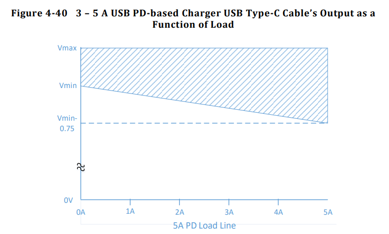
This Vmax and Vmin represent +/-5% of the allowable voltage. At 0A, there is no drop on the cable, but at 5A there is an allowable 750 mV drop. Interestingly, this drop is not symmetrical- only a 250 mV drop is allowed on the ground connection (even though it should have the same current flowing through it). This voltage drop at 5A means that a USB cable is allowed to burn about 3.75W.
This means the worst case voltage to come out of a 100W PD supply and cable at 5A is really 18.25 V, which is really closer to 91W. However, as much as 20.25V can be delivered at 5A, for 101.25W (with an ideal 0 ohm cable).
This means to get the full power out of the lower allowable voltage chargers, (18.25V), the heater resistance will need to be 3.65 ohms. however, that will draw too much current on the high side. the solution seems to be to cater to the lowest voltage, and then PWM the heater (which I will do anyway) so that it does not exceed the average current draw for higher voltage/lower resistance supplies. Designing around the higher voltage supplies will result in a under-powered design, since we will not get the full 5A at lower resistances.
Additionally, there needs to be some allowance for other resistive circuit elements, e.g. the switching FET, solder joints etc. Estimating a few 300 milliohms for those seems ok, so so the real target heater resistance should be about 3.3 ohms at room temperature.
Resistance Temperature Sensitivity:
Resistance of materials increases with temperature. Copper increases about .0039 ohms per degree ohm. With a delta T of 175K, and a target resistance of 3.3 ohms, this means that the resistance will increase by 2.2 ohms! This means that at higher temperatures the maximum output will be closer to 72W.
It is easy to calculate what original resistance would give us 3.3 ohms at 200C- this turns out to be about 2 ohms. However, the bulk capacitance required to smooth out the ripple at 10kHz is about 1000uF, which is expensive to implement. Using an electrolytic capacitors incurs a pretty steep power loss in parasitic resistance, and ceramic capacitors are too expensive for the design. I will stick with 3.3 ohms for the design, and just loose some power generation at higher temperatures.
Heater Design Math:
What follows is a detailed design of the heater traces. An important concept is sheet resistance- this is the concept that the resistance of any square of material in a homogeneous sheet has the same resistance. 1 oz copper has a sheet resistance of about .5 mOhms, per square.
As we know from our previous calculations, the resistance of the heater should be about 3.3 ohms. We can use this equation to get the number of squares:

From this I calculated that the number of squares needed is 6600. This means the trace for the heater (if its made of 1 oz copper) to be 6600x longer than the width.
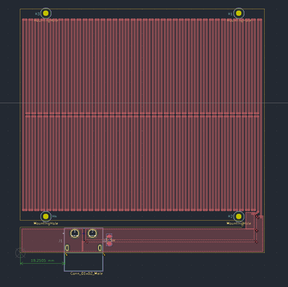
I want the heater to be about 100×100 mm, or less. This will give us an area of about .01m2, which was used in the calculations above for heat transfer. Ideally, the heater would be a little smaller, in order to hedge on the side of performance. Another practical consideration is putting the power terminals next to each other- this will minimize the length change between them when hot, and it will make the wires going to the heater short (preventing a wire run from another edge or corner of the board).
In order to meet these requirements, I wanted a rectangular pattern that would fill in the heater rectangle. I opted for what I decided would be called a double zig-zag, which can be cut anywhere on the perimeter so that the power terminals are next to each other. The extra long trace should also help prevent from stretching the copper under thermal expansion, since the whole pattern should act like a spring.
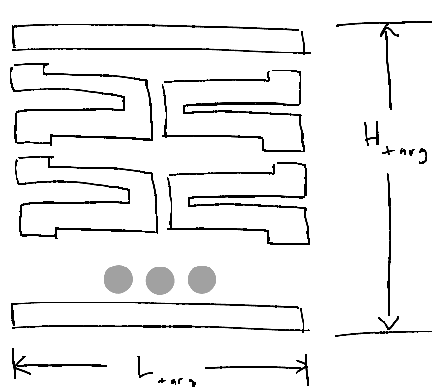
This drawing shows the units broken down- two long bars Ltarg long of width W, and several units that would each be connected to each other. Each unit has these dimensions:
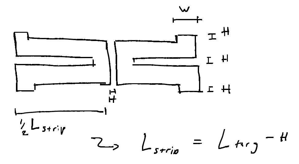
The ideal distance between the tracks, H, should be very small, because it will result in more coverage of the board in heater tracks, and therefore more even heating. I chose to start H at about 6 mil/.16mm. H needs to be varied so that the total number of units, N, is an integer. having a half-unit means that the spacing will be off or that it will not be possible to terminate the pattern properly. The next thing to do is to come up with a couple relationships for the geometry of the pattern. The first is that the pattern must be a certain number of squares long. This sum is the top and bottom width full length bars plus N units * squares per unit. The Number of units, N, also has to be equal to the target height of the units (Htarg – 2w) divided by the unit height. Here h is the spacing between units, and H is Htarget.

These first two expressions combine, after some work, into this ugly polynomial. we can now input an h, spacing between traces, and get out w. w allows for computation of N, the total number of units, which must be an integer to be valid. see plot below to compare red dots (N) to track width (mm) vs spacing, h (mm), as the spacing is increased.
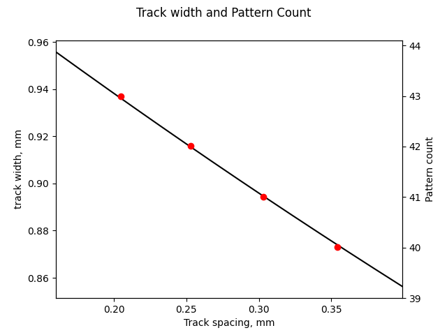
With this computed, it is easy to choose the best outcome, where the track thickness is maximized, and spacing is minimized, to create an evenly heated area.
Final design:
I decided that the heater dimension should be 100×76, since it is a little smaller than .01m2, which should give better performance at 100W. It is also a reasonable size for most PCBs I would make and under the price break dimensions for aluminum PCB.
Since the pattern can’t go all the way to the edge, and because the mounting is somewhat TBD, I decided to subtract a 1mm border on the long (100mm) dimension and add 4mm border on the short dimension. This makes the final dimensions for the board 100×100 (including connector), and the pattern dimensions 98×78 mm.
For a target track resistance of 3.3 ohms, the calculator reports that the width should be .996 mm, with .267 mm spacing, and 38 repeats.
Kicad Plugin
Of course drawing this trace is tedious and difficult to get right. A plugin was designed to draw the trace meander. Details can be found on git.
Next Steps:
The next thing to do is to ship the design off to be fabbed. I’m planning on trying both FR4 and aluminum substrate PCBs. FR4 has the advantage of having a similar linear expansion coefficient as copper, and being an ok insulator. Aluminum on the other hand, is possibly more rigid than FR4, and is a good conductor/heat spreader- this would be good to prevent heat buildup in any one trace. I will also need a controller for the heater, with a micro, a sensor for feedback, etc (post coming soon).

Hey,
Thanks for great explanation on this topic, really appreciated.
Currently, I’m working on a motor driver circuit that will operate max 150C ambient temp, and I’m planning to use SAC (need to use lead-free solder) solder paste which has around 220C melting point. I’ll select 155C FR4 PCB’s for my application but I’m wondering if my PCB’s will be decolorized after reflow, do you have any comments ? Do I need change my solder paste with a new one that has around 170C-180C melting point ?
Hey Yusuf- it depends on the silkscreen/soldermask that is used, and what your reflow method is. For a pcb hotplate, the interface of the heater pcb and the soldered board can get very hot (and that temperature is not usually controlled). The pcb heater needs to be above the target temp of your soldered board, because the top of the soldered board is cooled by convection.
In an oven, the pcb/solder is heated on all sides, so you don’t develop a thermal gradient across the soldered PCB in the same way. This means the underside of your board does not get toasted.
Some soldermasks/silks are more durable than others. I only tested that one adafruit board, so I can only tell you about that specific combination. That said, it might just be a visual defect and not something that will hurt the board (although if you use 155 Tg pcbs it might hurt the board).
With respect to SAC vs other alloys, there are only so many alloys that make good electronics soldering materials. If you find a lead free alloy in the 170-180C range it may be expensive/hard to get or have some other caveats. SAC might be your best bet. If you are hand assembling, you might be able to use a hotplate as a preheater and finish the heating off with a hot air gun.
Hey Avery,
Thanks for the comments and your advices.
I’ll try to cook my PCB’s on the hot plate carefully first, and if I can’t succeed, then I’ll buy an owen to cook, and try to improve silkscreen quality.
You have a great blog btw, congrats!