The hot plating continues! And with the boards actually in hand, I can compare my estimates to some real world measurements.
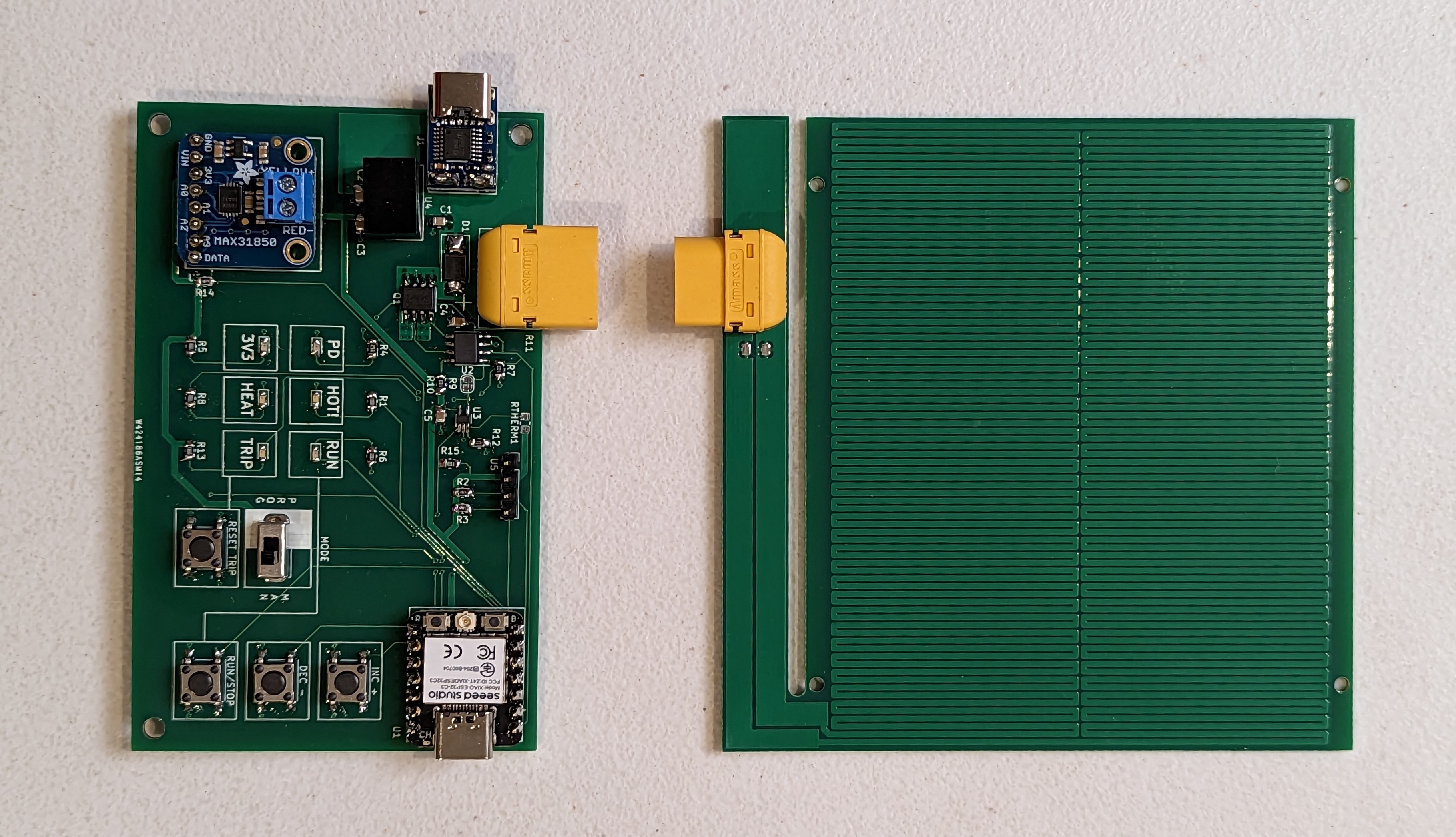
In the end, I made both FR4 and aluminum heaters. These heaters ended up having slightly different properties. Oddly, the aluminum PCB has a higher resistance (4 ohms) than the copper pcb, 2.9 ohms). Read on to figure out what this did to the design.
Designed Vs Measured Resistance:
The design resistance of the heater track was 3.3 ohms. Clearly, this was not “nailed” for either of the boards, but it was close. I was surprised that both boards didn’t overshoot the resistance, due to the addition of a few extra squares of conductor on the connector island- however the FR4 heater seems to have a more generous allotment of copper, and the aluminum PCB may have slightly less copper.
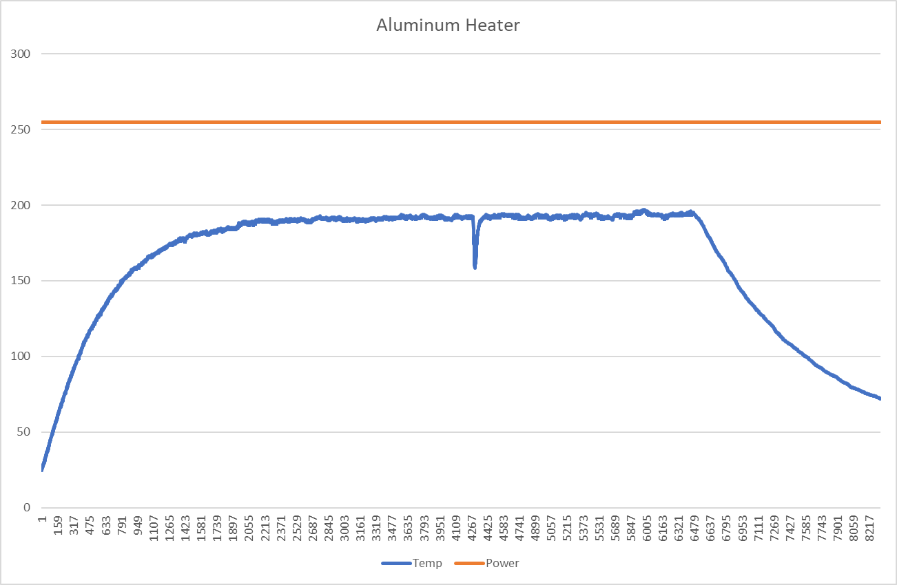
Unfortunately, this means that at higher temperatures, the power delivered to the aluminum board is much lower than desired. The calculated value for the resistance at 200C is about 6.7 ohms, and the measured value is 7-8 ohms. This means that the maximum power available at 20V is 50-60W, or less. This is pretty close to the theoretical minimum power needed to reach 200C, which is why this plate struggles to achieve 200C. As you can see, the heater is on for the entire time (until I pulled the plug). Time units are in 10ms intervals. Fortunately, this validates the power delivery assumptions I made in the past post.

To recap, Qdot is the amount of heating power needed to sustain a particular delta T, given some convection parameters. I assumed a delta T of 175k, with an area of about .01m2, and h being 25 W/m2k, resulting in a power delivery at the heater of 43W. while this is not totally spot on, its in the right ballpark. It suggests that lowering the resistance and actually delivering 100w would be very helpful to removing this 200c limit. I think 10-20 is a reasonable conservative estimate of convective cooling, but its conservative in the wrong direction if you are designing a heater.
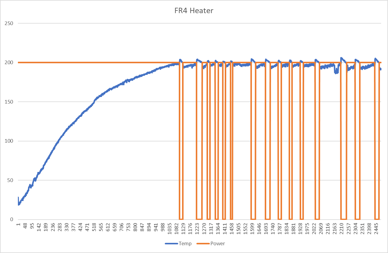
On the other hand, the resistance of the FR4 heater is low. At low temperatures, running at 100% PWM (all on), will cause the power supply to brown out. This means that the power delivery actually needs to be cut back (PWM’ed) when the heater is cooler, so that the overall current draw is lower. Once the heater is in the vicinity of 100C, it can be run “full blast”, aka more or less shorted across the power supply.
Does It Blend?
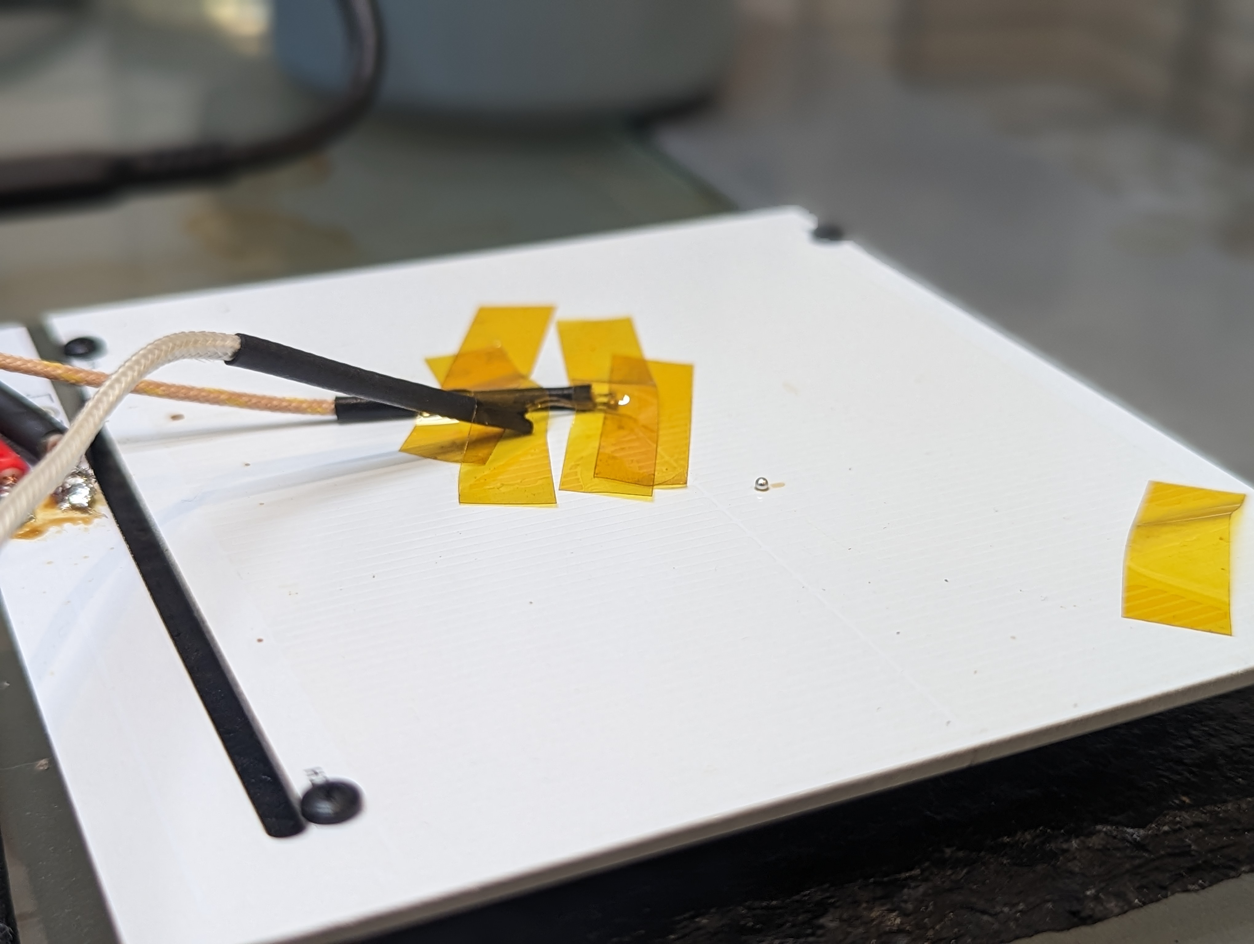
Both the aluminum and FR4 heaters were able to reach 200c depending on the conditions. Both were capable of melting solder directly on the plate, as you can see. The aluminum heater would benefit from an improved (lower resistance) heater trace.
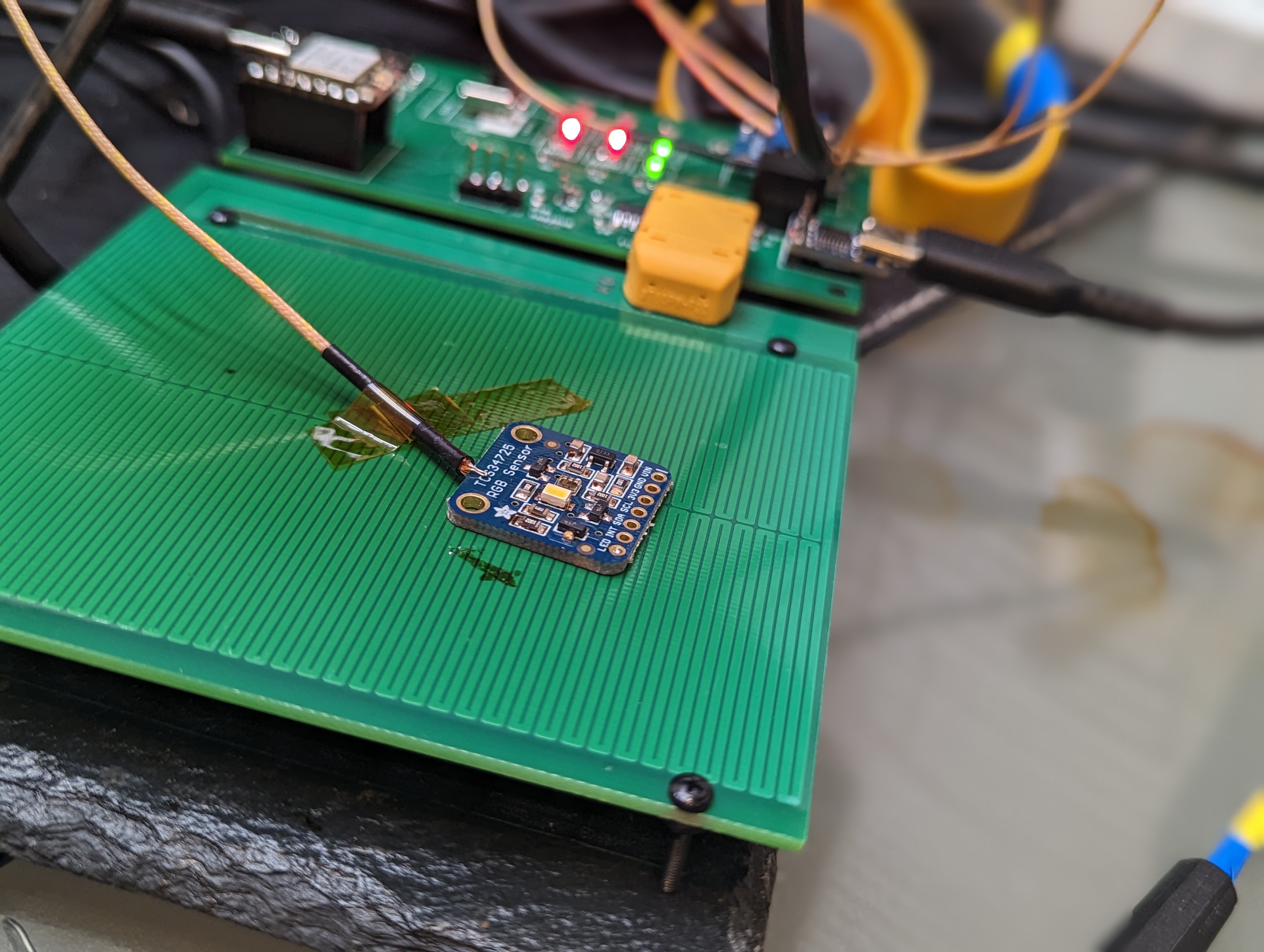
The remote probe feature allows for the sensing of the temperature of the PCB being soldered. This is good, since that is where the temperature actually matters. This can cause the heater to get much hotter (20c or so) than the top of the target board, which in this photo, resulted in some discoloration of the solder mask of the heater.
Temperature Gradients and Overheating:
The hot plate design needs to achieve two tasks: be cold at the connector (so as not to de-solder it), and it needs to be hot (and ideally, evenly hot) across the surface.
The worst case for de-soldering the connector is with the aluminum heater, since the aluminum substrate should conduct heat pretty well. Up at peak temperatures, the connector area only got to about 85C. Certainly warm, but not nearly hot enough to damage the connector.
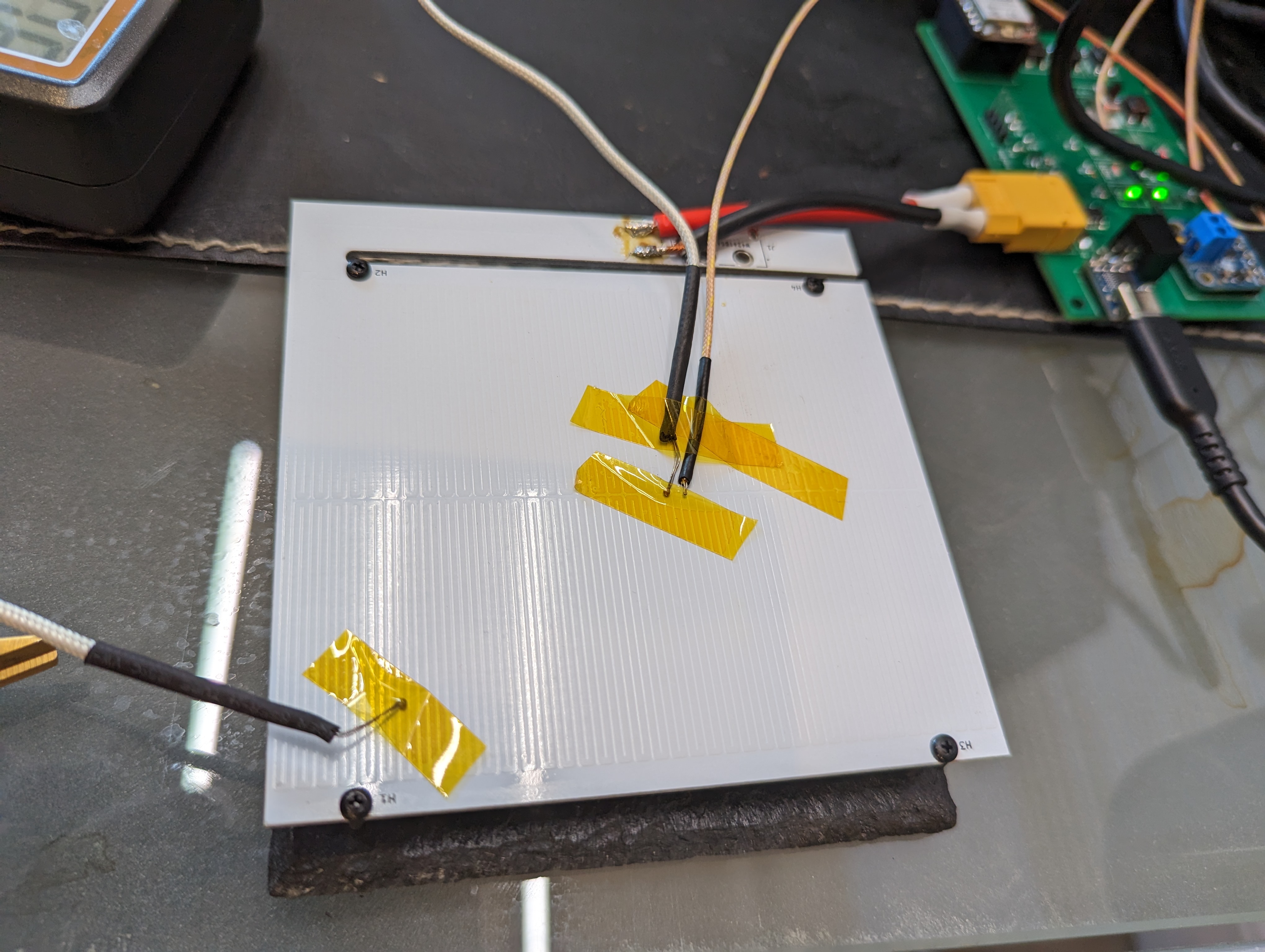
In terms of heater gradients, the aluminum PCB had about a 10C difference from the center to the corner at 200c. The gradient to the “neck” of the connector island was much worse (13+ C), since the thick traces there (and the substrate) act like a heat sink. The corners are cooler since there is some radiation and extra convection out of the sides of the heater.
The FR4 board has a even higher gradient, in excess of 50C during heat up, and staying steady at about 50C after several minutes. This is annoying, since it makes the outer areas of the PCB too cold to solder on. The center can be overdriven to compensate, but that leads to overheating and discoloring the solder mask.
New Design Goals + Limitations:
Its clear that hot plate soldering is not the ideal way to solder- something like a toaster seems a lot better and faster, since it can more evenly heat the target PCB. The main issue is that in order to get the top of the PCB hot enough to reflow, the bottom has to be quite a bit hotter. This is worse with traditional lead-free solders, since they need to hit about 220C. Lead-Tin eutectic solders need to hit 185 or so, and bismuth lead-free solders only need to reach 140 C (there is a medium caveat here).
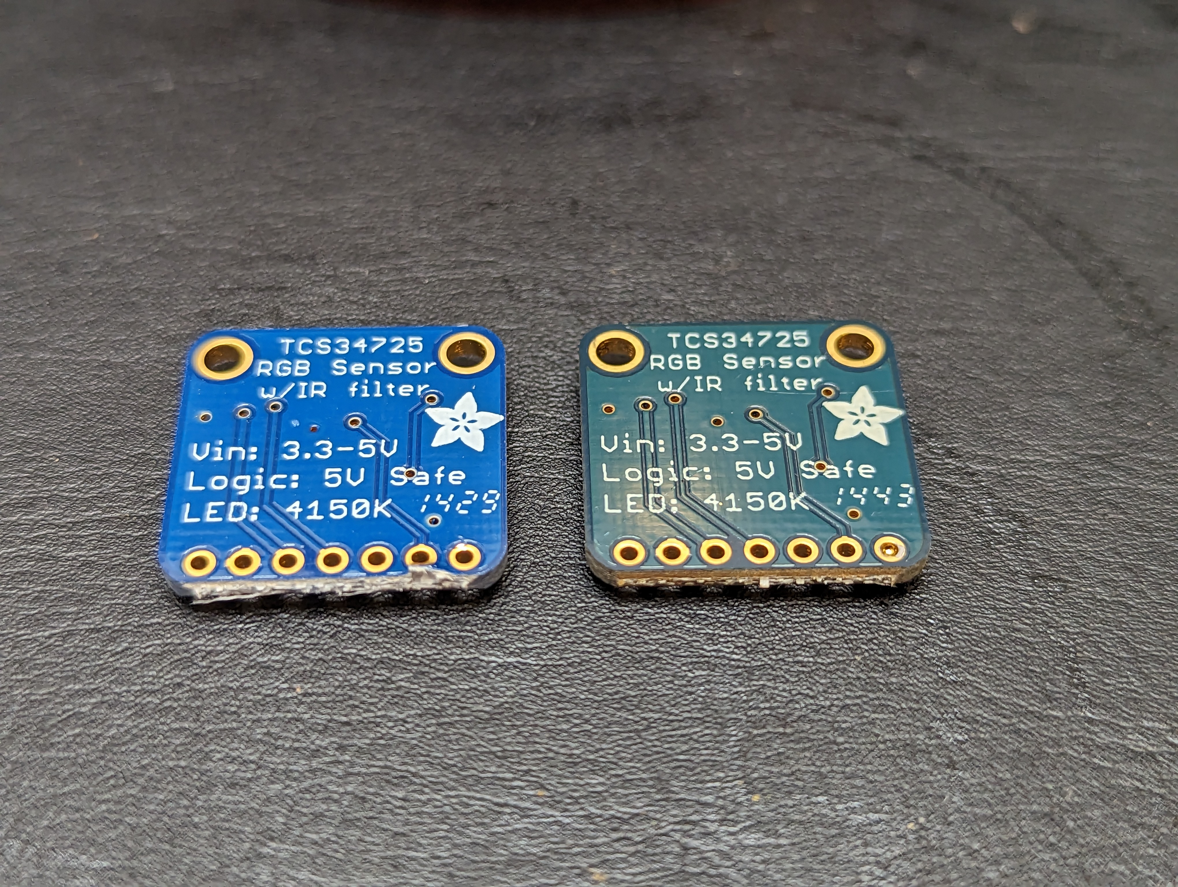
You can see the results of this heating on an adafruit board (above), that I gently reflowed. The left board is new from adafruit, and the right one is reflowed. It didn’t really damage the board, but it certainly would be an unacceptable outcome if a manufacturer overheated a board like this, and the lead free solder (I assume) on top barely reached the liquidus point, and would re-solidify as soon as I moved a component.
The medium sized caveat is that any lead in the process can poison your bismuth solders forming a bismuth-lead crystal that has a very low melting point (95C!). I think the jury is still out on using bismuth solder for stuff that gets hot, but for most prototyping it seems fine. For low temperature solders, the hotplate is fine because your whole board stays under typical soldering temperatures.
For leaded solders the hot plate will likely also work ok, since the heater can be at about 200c and the surface of the target PCB can be at 180. However, for lead-free SAC (Sn Ag Cu) alloys, I think the hot plate will likely damage the solder mask of the target PCB. However, using the PCB hotplate as a preheater could work fine, with the addition of a hot air gun assist.
I would like to use this hot plate to solder and test complete prototype designs, with packages that are hard to hand solder, particularly leadless stuff like QFNs. I find solder fumes to be irritating (and there are more at higher temperatures), and so I am going to try using the bismuth solder, at least for prototyping. For leaded work, I’m pretty sure the hot plate would work fine, and it will be a good tool (combined with hot air) for reworking SAC alloy lead-free boards. I’d also like to take up less closet space than a toaster oven, so I think the project does have some value. It also fits in nicely with the USB-C powered soldering iron ecosystem.
Electrical Stuff:
In the previous posts I shared some choices around the electrical system. The two concerns I had were not shorting out the power supply, and preventing inductive spikes from exceeding Vdsmax.
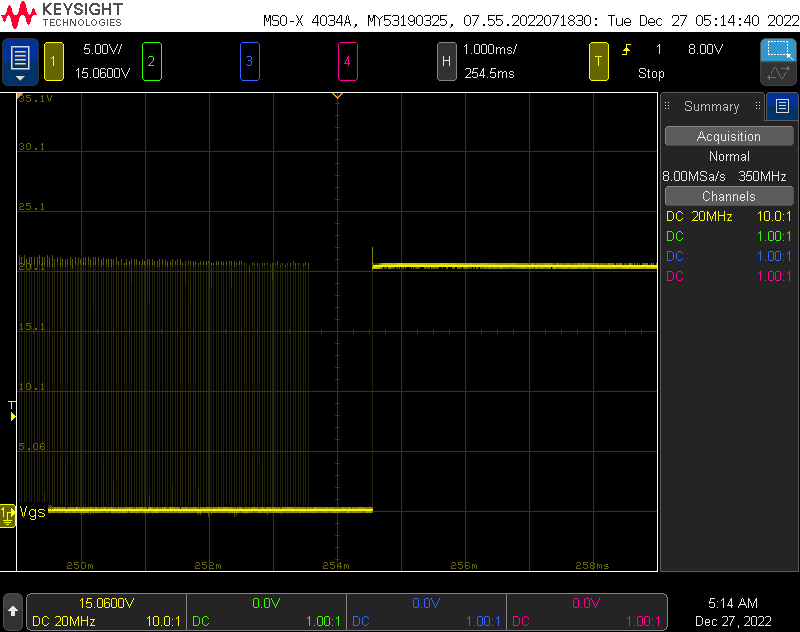
The Vgs, shown above, was totally fine since it was limited by the free-wheeling diode. Even with a 1ms charge time, the inductor failed to exceed 25V and there was very little ringing. The Vdsmax is about 30V, so there is plenty of margin.

To test power integrity, I wrote some code to turn the heater on different power levels for 10ms, starting at 100% power. As you can see, 100% power reduces the output voltage just a bit, to 19.5V. This is well within the PD specification. When the PWM begins, the power supply seems to tolerate some relatively large spikes/dips as the heater (inductive load) is switched at 25kHz.
Electrical + Control Improvements:
To get a truly performant hotplate, the resistance at 200C needs to be less than 4 ohms, so the full 100W (or close to it) can be used to maintain the target operating temperature. Doing this is tricky, because it means that at 25C the heater can’t be operated at 100% duty cycle. Basically, power is not a function of duty cycle, but of duty cycle, temperature, and board characteristics.
There are two approaches to solving this problem. One is a per-heater lookup table, that lists a reasonable safe duty cycle per temperature. This is limiting since it would need to be generated per-heater, but its not unreasonable to do that given that I will likely stick with a single heater, and most heaters should be pretty similar.
Another approach would be to add a current monitoring to the USB PD supply, and cut the heater power off once you get close to the limit. This requires a relatively high bulk capacitance to provide current, even at 25kHz, but its certainly achievable. Overall power could be modulated by adding a dead time in between heating cycles, in order to follow a temperature profile. Higher frequencies could be considered, taking into account the switching time of the low side FETs. This is basically a current-controlled buck converter.
I’ll likely stick to the first approach for now, since doing current limited control requires more hardware, and it is unlikely to really improve the outcome of my soldering.
Mistakes + Takeaways
There were a few minor circuit goofs, and some things that went surprisingly well. Here is a small list, that might help you or me in the future:
GPIO9 and GPIO8 on the ESP32 C3 are bootstrapping pins– they control what the ESP does when it boots. I connected one of them to a switch, as an input for the program. This meant that the ESP would not boot into my program, but it would boot back into bootloader mode (and accept new programs). Toggling the switch made the ESP behave normally. Note to self: use these pins carefully.
The pinecil is a pretty beefy iron. It had trouble soldering to the aluminum PCB, but with boost mode and patience it had enough power to solder directly to a 3mm wide trace on an aluminum substrate. It had NO trouble soldering XT60 connectors to large pours. Don’t let the small size fool you- it is a real iron.
It is a good idea to put indicator LEDs on things like the actual power rail and the actual HEAT signal. It makes it unambiguous that something is really happening, and that the heater is getting hot.
I added a solder jumper to the overtemperature cutoff circuit. I accidentally swapped the inputs on the monitor chip, so it didn’t work. Cutting the jumper made it really easy to test with this protection turned off.
All my temperature sensors gave wildly different readings, even when co-located. I’m not sure why, but I do trust that the delta temperature measurements were ok since they were from the same instrument with two of the same probes, and they had the same readings when physically connected.
USBC-PD can deliver serious power, and its easily obtained with USB PD trigger boards.
Next Steps:
During testing, I learned what this type of soldering setup is really appropriate for, and what the capabilities of the heater are. I want to try some of this low temp solder, and I want to do some hot plate soldering to figure out how it feels, before going back to take another pass at the heater element. I suspect targeting an even lower heater resistance will allow me to hit 200C easily with the aluminum plate.
I also have some work to do on the UI (there is a screen- I just didn’t plug it in), and on the controls. If I find it useful, I will probably build an enclosure for it to protect the electronics and to make it easier to use.

Thanks for letting me know what this type of soldering setup is really appropriate for, and what the capabilities of the heater are.