GelIS Production Pt 2: Laser Cutting Time!

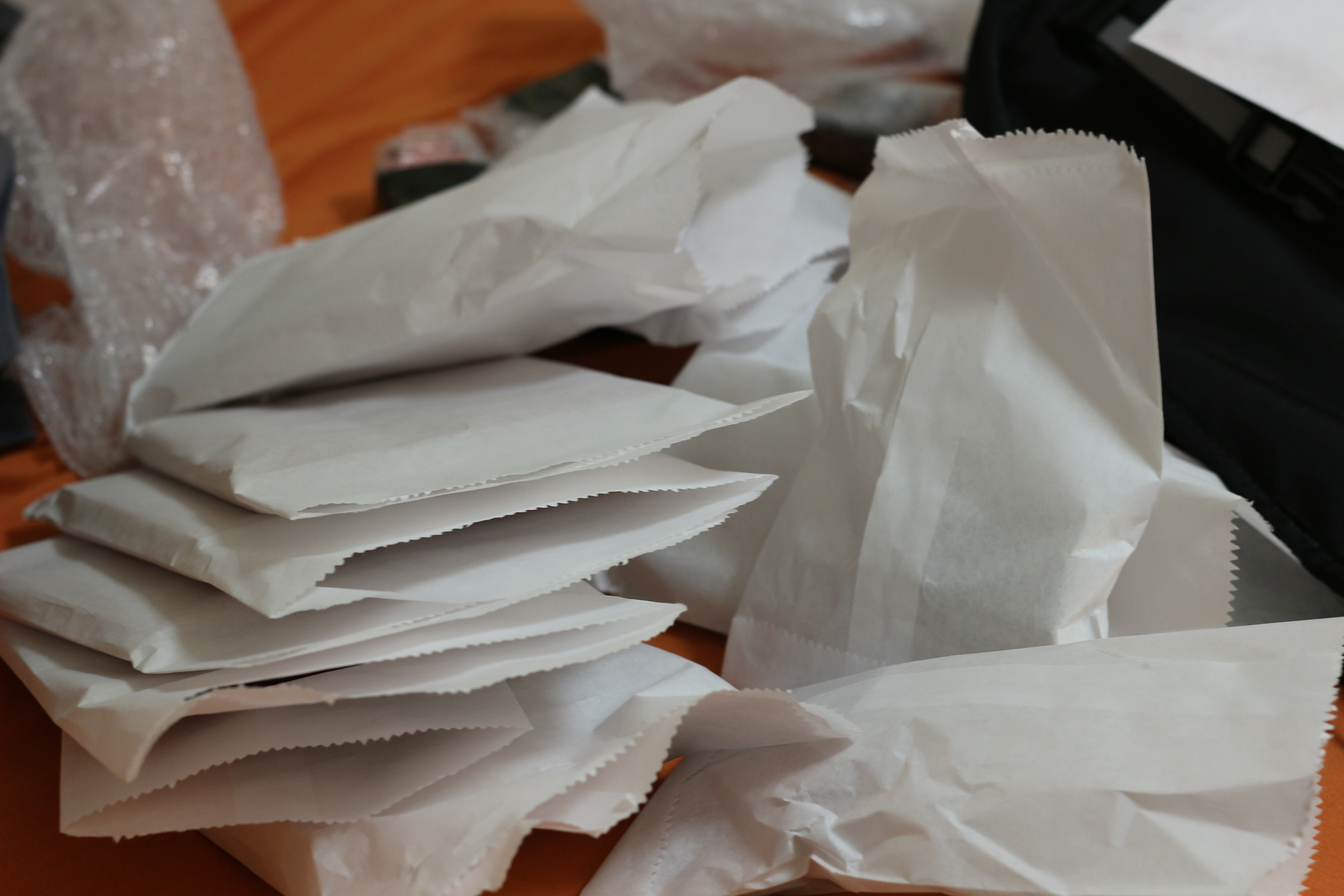
parts for future gel boxes!

parts for future gel boxes!

Today I hauled about 10 pounds of assorted acrylic 15 miles into the city of Cambridge and back to where I live.  The journey took about about 7 hours, and about four hours were spent laser cutting!  Of course, that is operator time, not tool time.  Since I am cutting, the big factors to control are material usage and tool time.  I cut the boxes at danger awesome, which charges $2/laser minute, meaning if you cut for 5 minutes, you are charged $10.

This makes part packing really, really important.  Part packing is the positioning of each part on the sheet that it will be made of.  Like many spatial challenges (routing PCBs, putting linkages on different planes, etc.) in engineering, there are probably tools for this, but there is certainly a sense of satisfaction in using your very own brain to solve the problem.  While the box was designed with fabrication in mind, I hit some speed bumps during cutting and learned a lot.

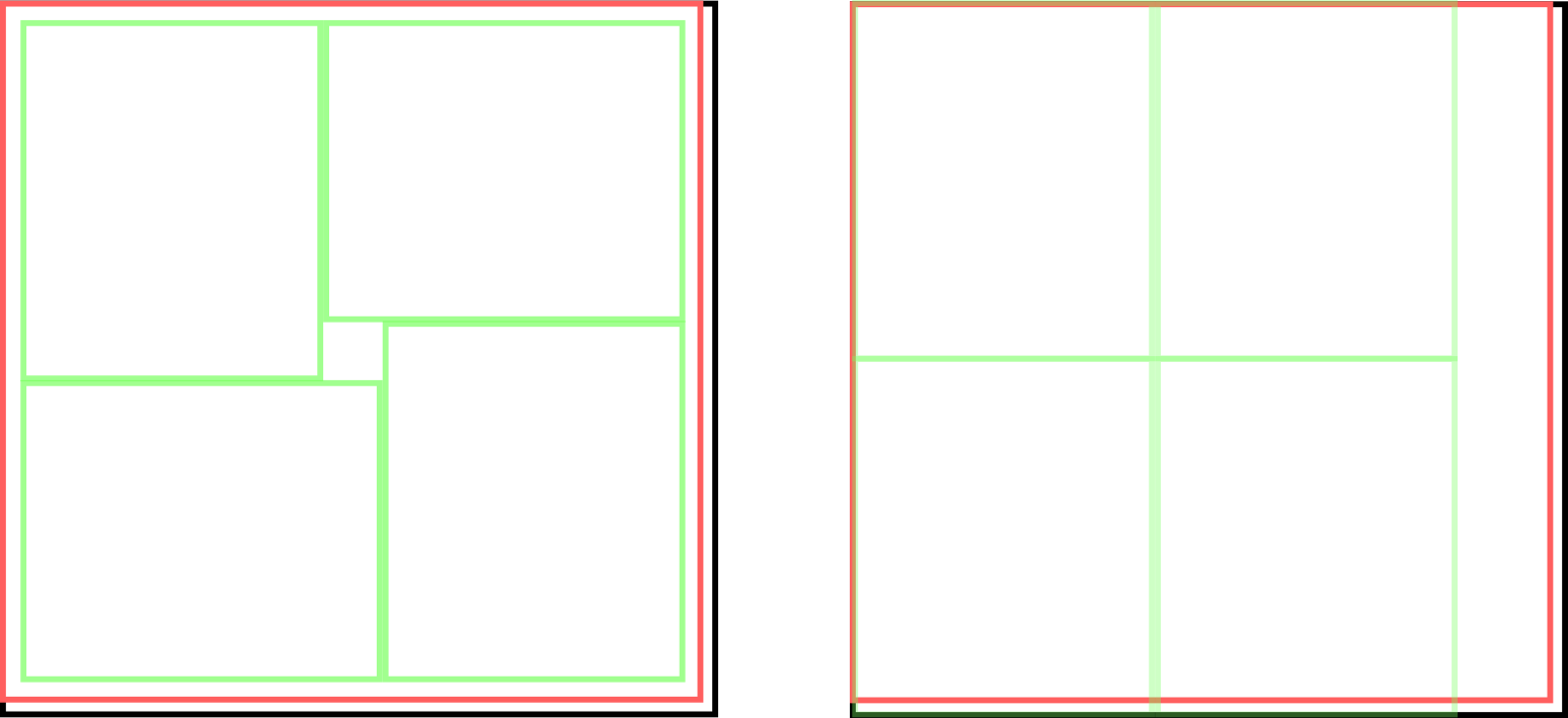
cutsheets

Black edge- 12 x 12 rectangle
Red edge- actual sheet
Green edge- parts I made

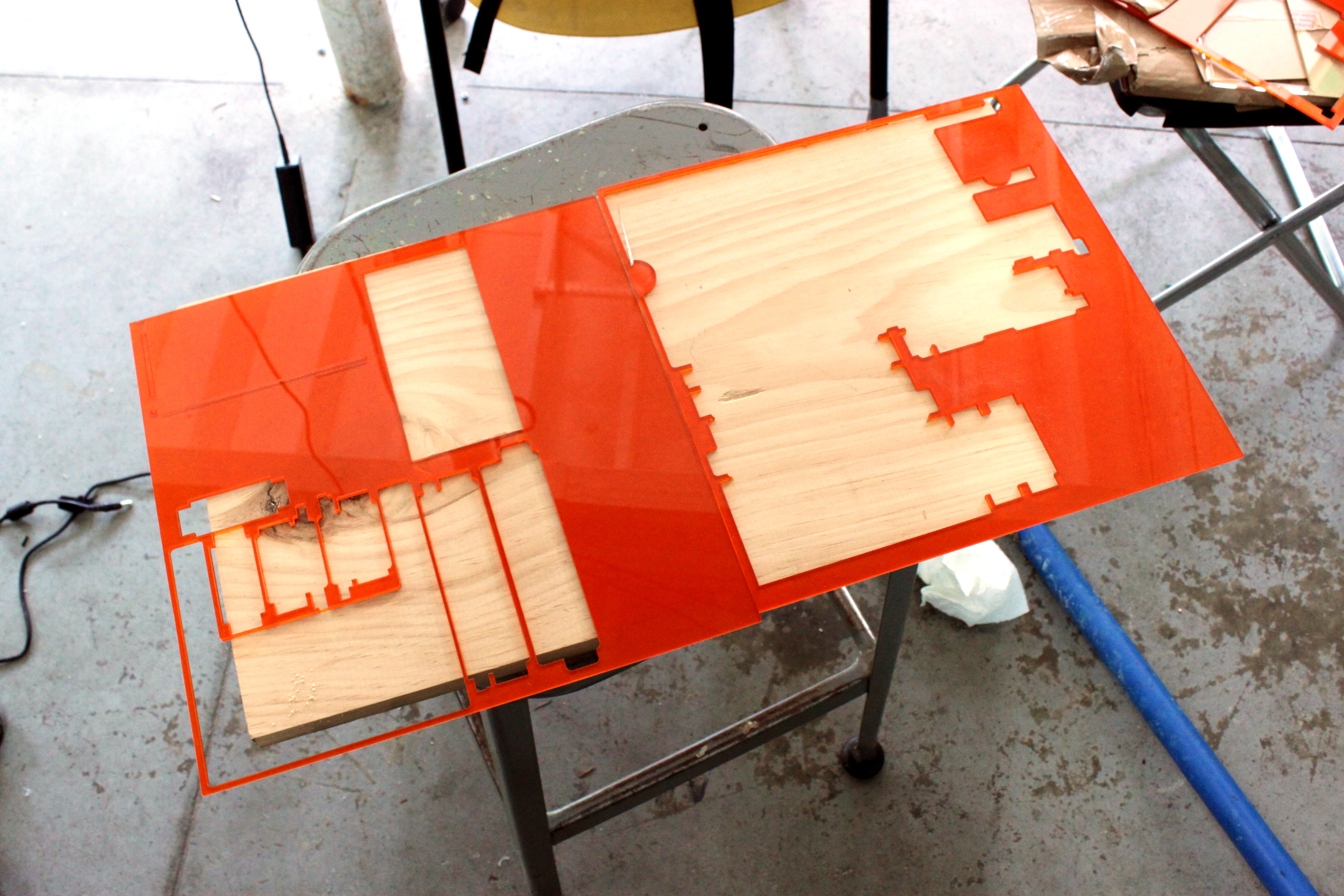
The first problem was that the parts I wanted to cut were 6×5 inches and would barely barley fit on a 12×12 sheet (as seen on the right).  I am pretty careful, and given a few thou over 12″, I was pretty sure I could cut out parts per sheet, like on the right- but the sheet was smaller by 1/8-1/4″ on each side!  So I went ahead and re-arranged the cusheet in coreldraw into a pinwheel shape (strangely, corel is much better than solidworks for this), and I ended up with excellent results, as seen below!

IMG_2122

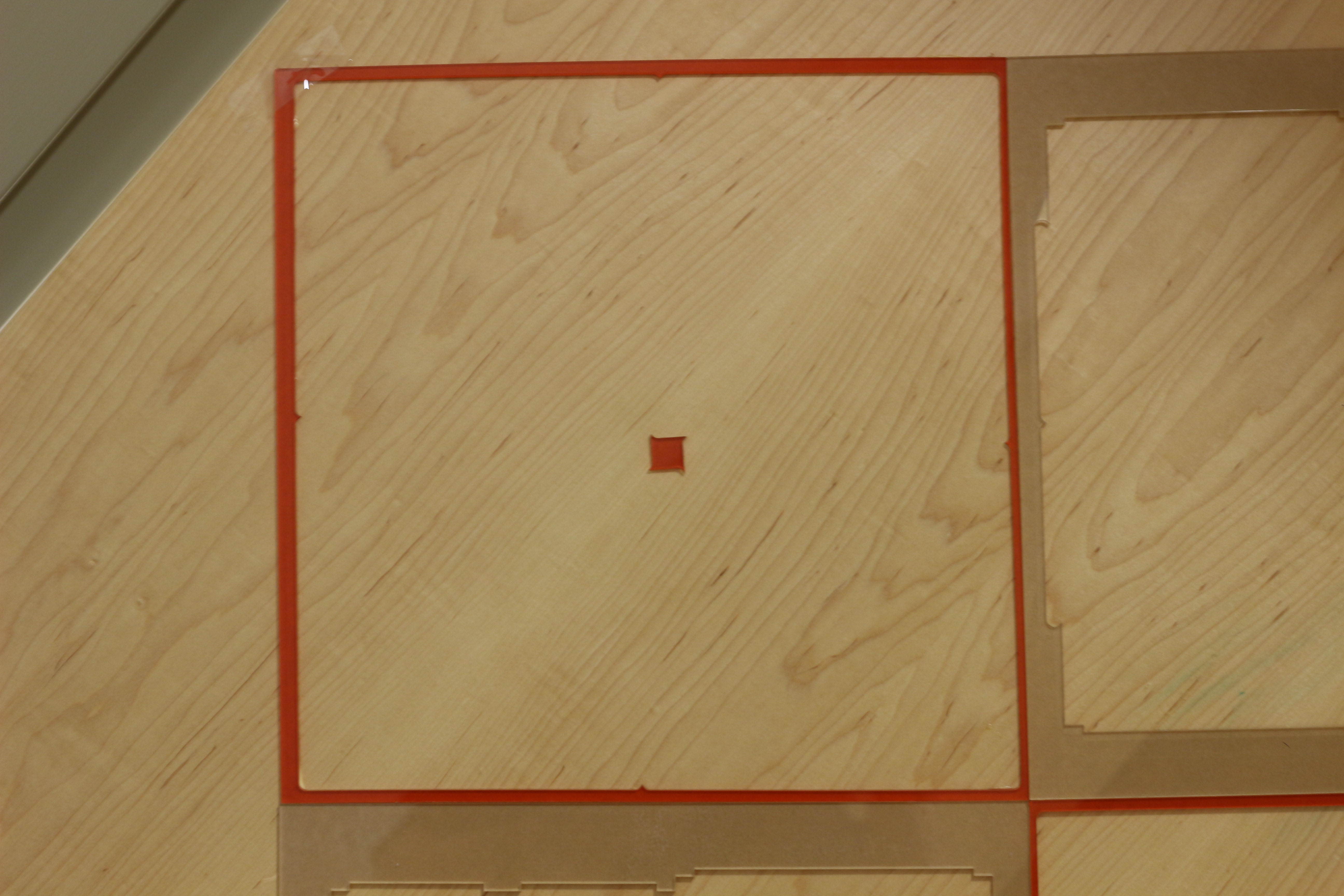
The nice thing about packing parts like this is you get to share edges, which is basically 50% off the cut time for that edge, plus you save on material between parts and have a lower chance of melting or warping parts with nearby cuts.

IMG_2121

One of the nice things about the gel box is that most of the parts have similar-sized notches cut in them for mortise joints.  By keeping these the same throughout the box, the parts are easier to arrange, and they can share cuts!  A tip here is to make groupings of parts, and arrange them (sharing edges) into mega-parts that have edges that are easy to share with other mega-parts.  That is how i ended up with these cutouts being so clean.  You can see on the bottom two cutouts that the parts were mirrored across a horizontal line, and on the top the parts were pinwheeled again.

This might be it for the notes on making the gel system- I could write about boxing it all up, but I haven’t discovered a good way to do that except to do it while drinking a hot beverage or while watching a movie.

GelIS Production Pt 1: Lead Times

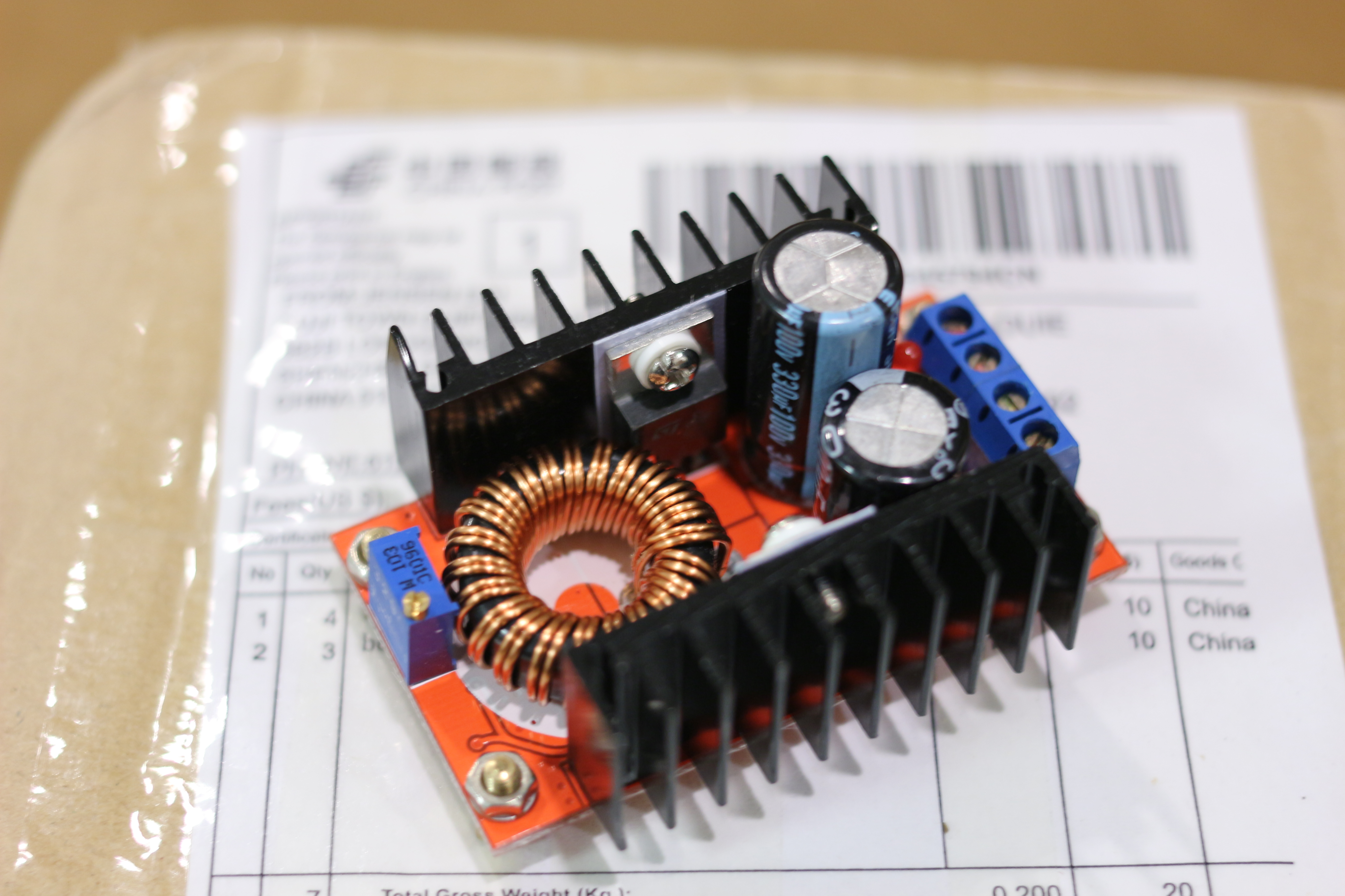
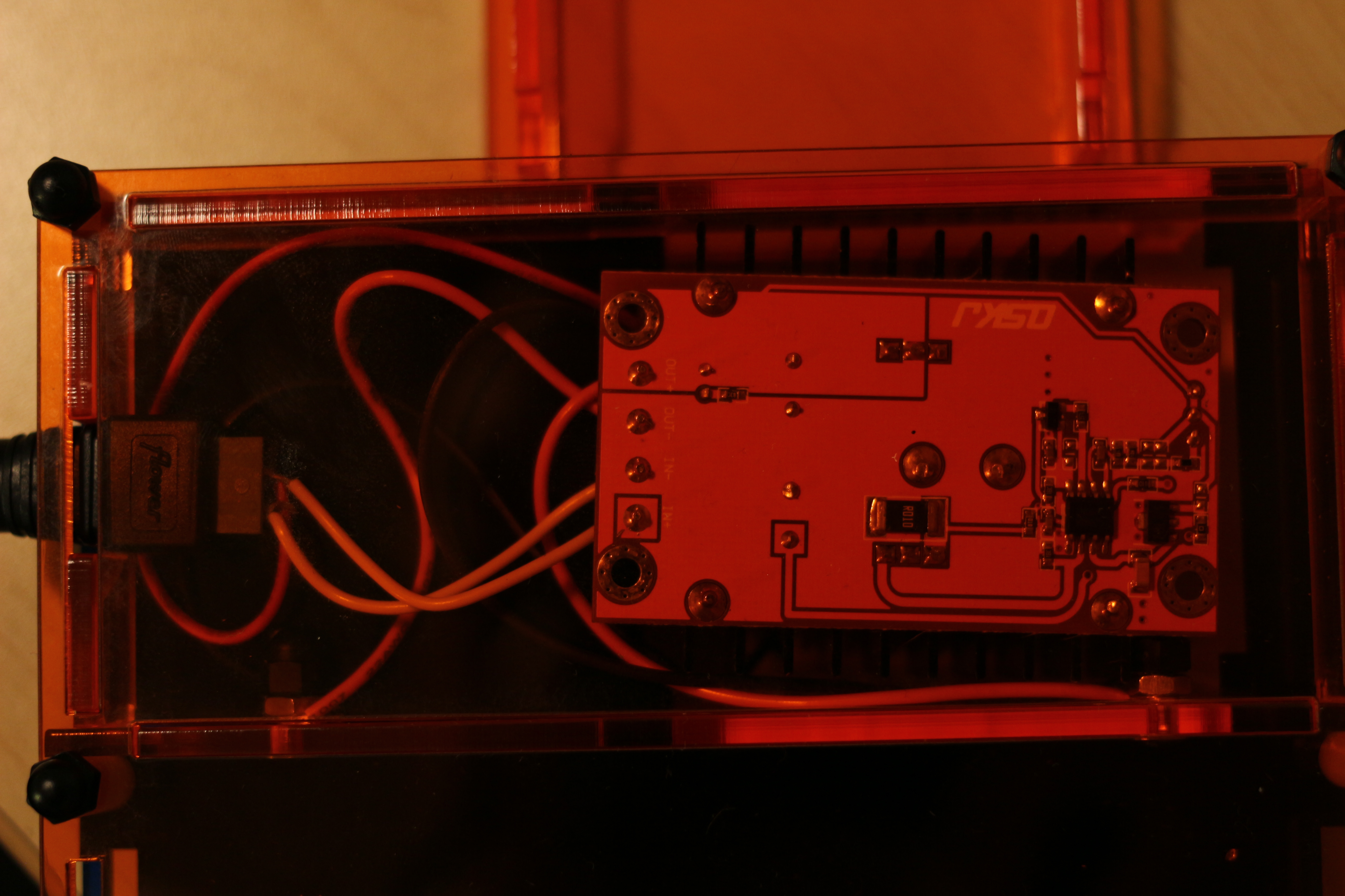
DC-DC converter, the heart of the Gel Power Supply

DC-DC converter, the heart of the Gel Power Supply

Sourcing this part is critical to being able to continue to sell GelIS.  Unfortunately there is an incredibly long lead time on these parts, as they come from China.  My strategy is to generate a few orders for the box, and then order extras far far in advance.  I hope it works!  If the rate of orders keeps up, I should be ok, but otherwise delays could happen!  I will have to think carefully about this.

Gelis: Final Cut

GelIS- Final Prototype

GelIS- Final Prototype

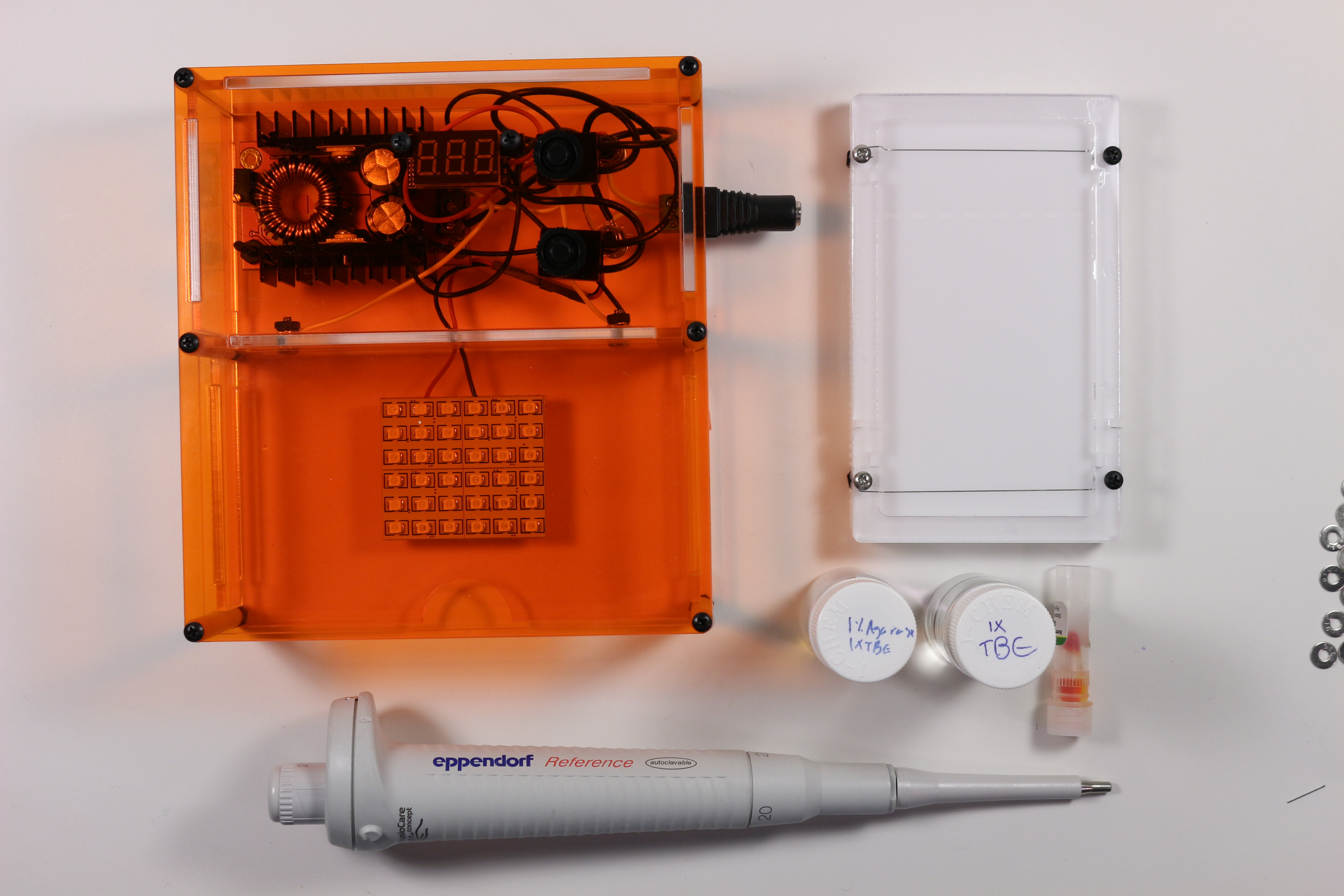
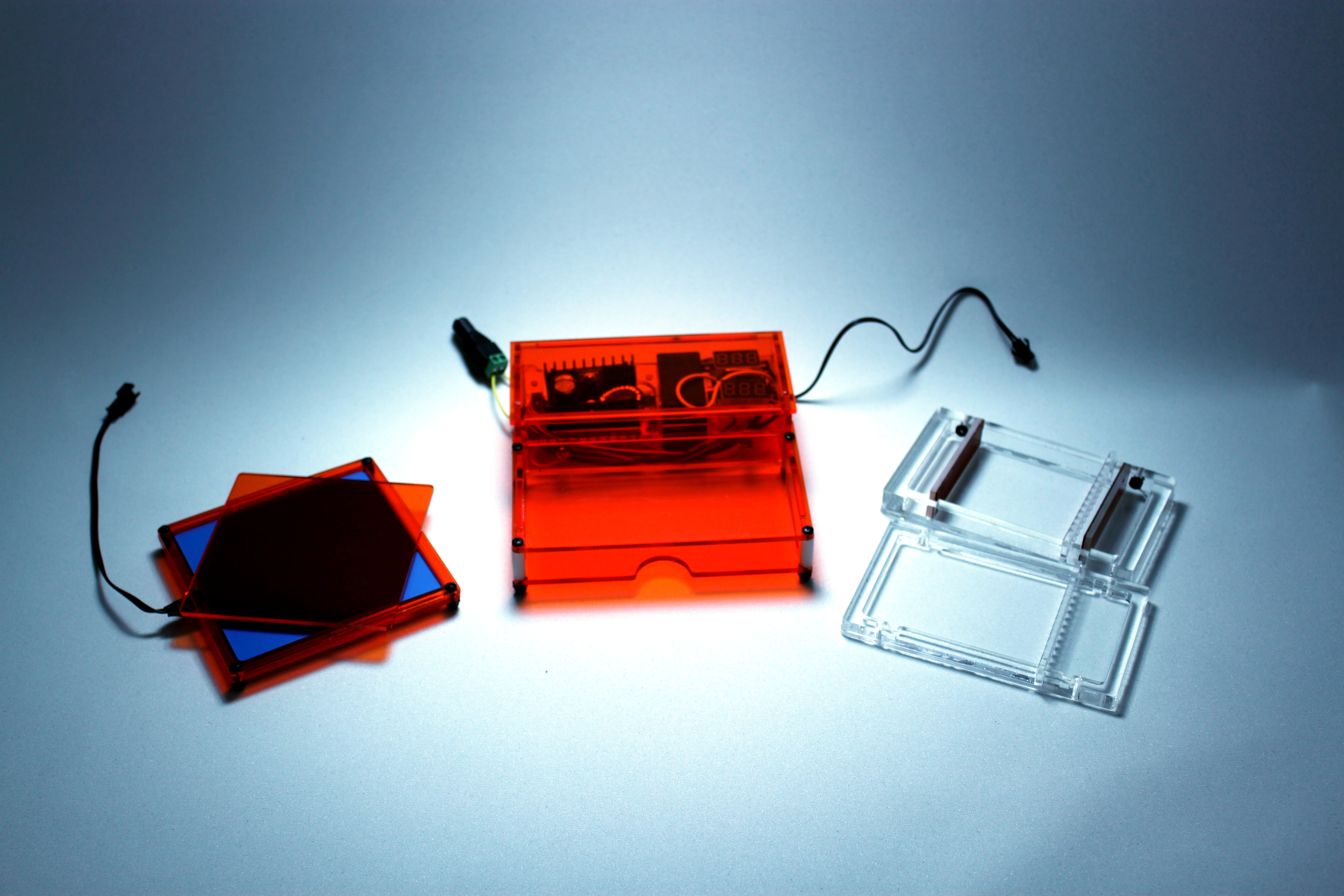
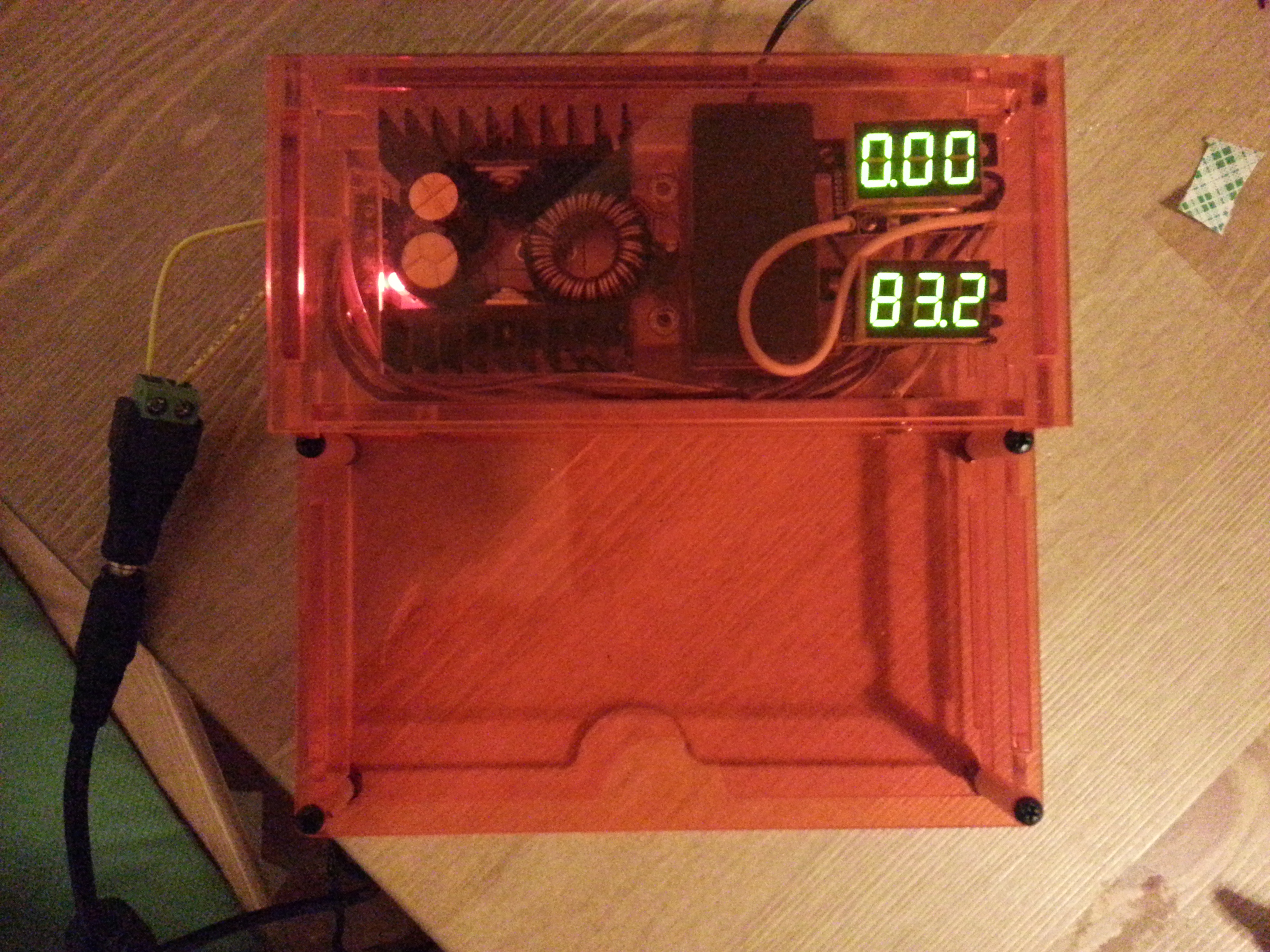
The Gel Integrated System is done.  I have packed an electrophoresis power supply, illumination, and casting system into one tiny box.  All the parts, other than the enclosure, are off the shelf parts.  It can be shipped flat and assembled with only a screwdriver.  This all comes in at a sale price that is an order of magnitude lower than commercial systems, with a bench footprint an order of magnitude lower than commercial systems.

Test Run

Test Run

It has been tested, and it is completely functional.  The gel is bright enough that you can take pictures of it with your cell phone.  If you want to get one, I will be selling the first batch of ten here for $200 a piece.  Use that link to contact me if you need a large batch, or find me on the diybio mailing list.  I will hopefully have an assembly video (and feature video) soon, but until now you can see my instructable on assembly here.

GelIS Simplified

The latest GelIS prototype

The latest GelIS prototype

Almost ready to test the latest prototype!  Everything electrical is go, but I managed to loose my LED panel in my moves from showing my prototype in CA, visiting the bay area, and them moving from an apartment in Somerville back to school.  Oops.

IMG_1401

One of the major improvements in this prototype is simplified wiring.  I did away with the ammeter (since it was on the fritz anyways), and now it is very easy to assemble with only a screwdriver.  The improvement is that lots of wires don’t need to go into screw terminals now- there is a max of only two wires per terminal, and if you wrap stranded wires around solid wires, you have a pretty solid connection.

I am really looking forward into getting these into peoples hands!

GelIS: Light at the end of the Tunnel

GelIS Tray Holds Water

GelIS Tray Holds Water.  You can see the water on the rubber dam, and it is totally contained!  Hooray!

This is the newly designed tray for the gel system.  It is a major improvement over the last tray, and it comes with some other major revisions to the box.  The big upgrades to the tray are:

  • about 2x cheaper
  • built-in diffuser
  • tighter slots for the dams (orange things in that picture) by .005″

This makes the tray system pretty solid, and the low profile saves gel and buffer, and makes it even harder to get your digits into anything that is electrified.  It also makes the box 100% cuttable, with no need to drill any holes, which was an issue since the laser cutters I use can’t focus on an object that is 3″ high.

The other major revision that is coming is an adjustable LED light source.  I love the EL panel, but it is tough to get a good photo without a decent camera, and it is just not as bright.  Even though the EL panel is great for me, I expect that some people will just want to use a cell phone, which is not feasible with the EL panel as it is. Heck, my phone is my lab notebook, and carrying around a big camera is inconvenient, so most of the time it is all I have (I am advocate of the lab having a camera).

With the dam sorted and the illuminator design tested, I am ready to call the next revision the minimal viable product and ship it out.

GelIS Prototype Two: Wet Test Success!

The Gel Integrated System in all its glory

The Gel Integrated System in all its glory

The second prototype of the Gel Integrated System is done.  I ran a gel on it (wet tested it) today, and I am happy to say that I am ready to sell, build, and ship the first few units.  There are a few minor revisions that will go out in the first few units, like a clear “lid”, and slightly different dimensions for the wire cutouts, but mostly they will be the same as what I tested today.

Here is a brief rundown of how the test went.

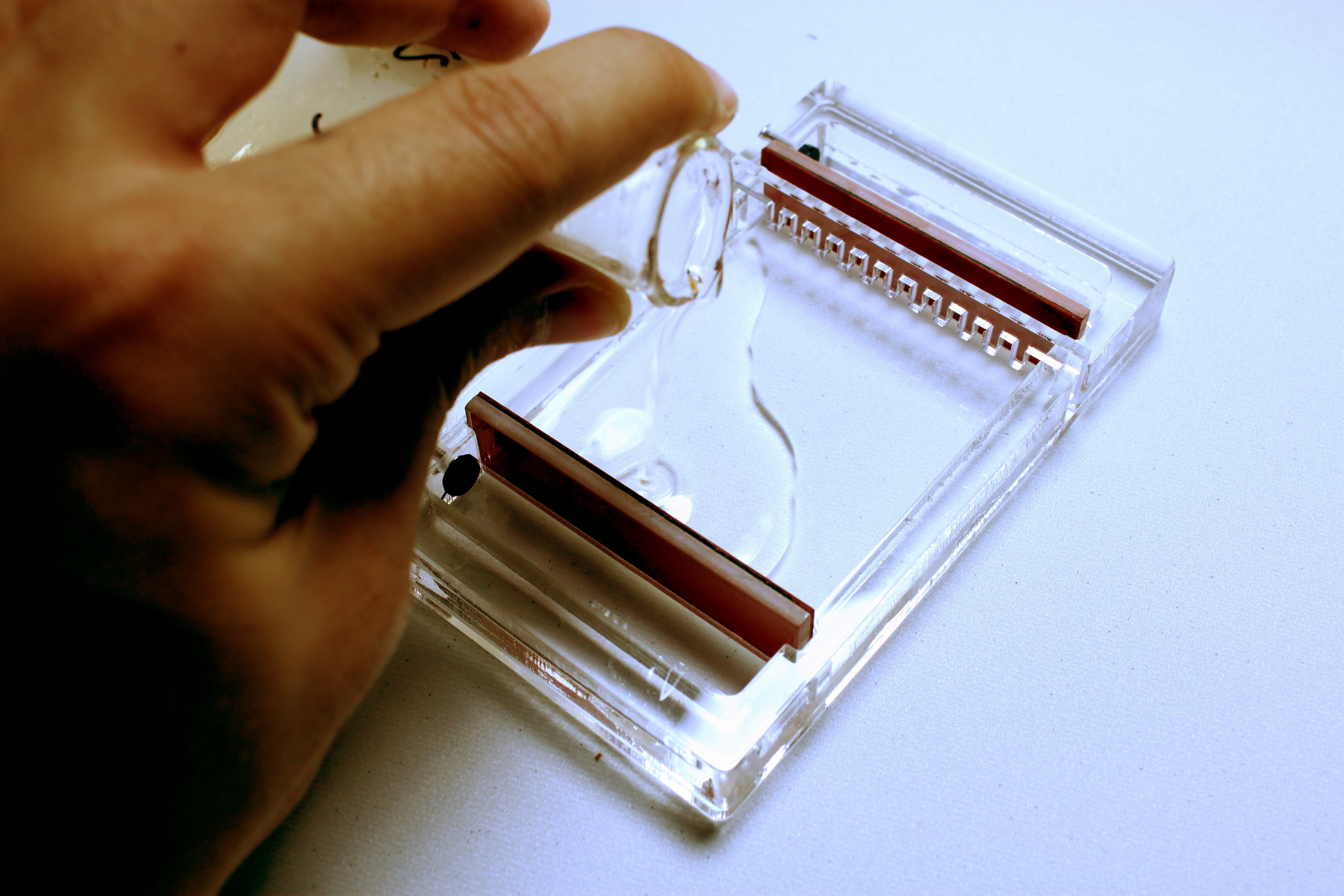
Pouring the gel, 1% Agarose in 1X TBE with gelgreen 5ul/ml

Pouring the gel, 1% Agarose in 1X TBE with gelgreen 5ul/ml

Pouring the gel started out ok, but I need to get the seals a little wider and the slot that they go into a little thinner, so they seal.  The leakage I experienced should be a non issue for future users.

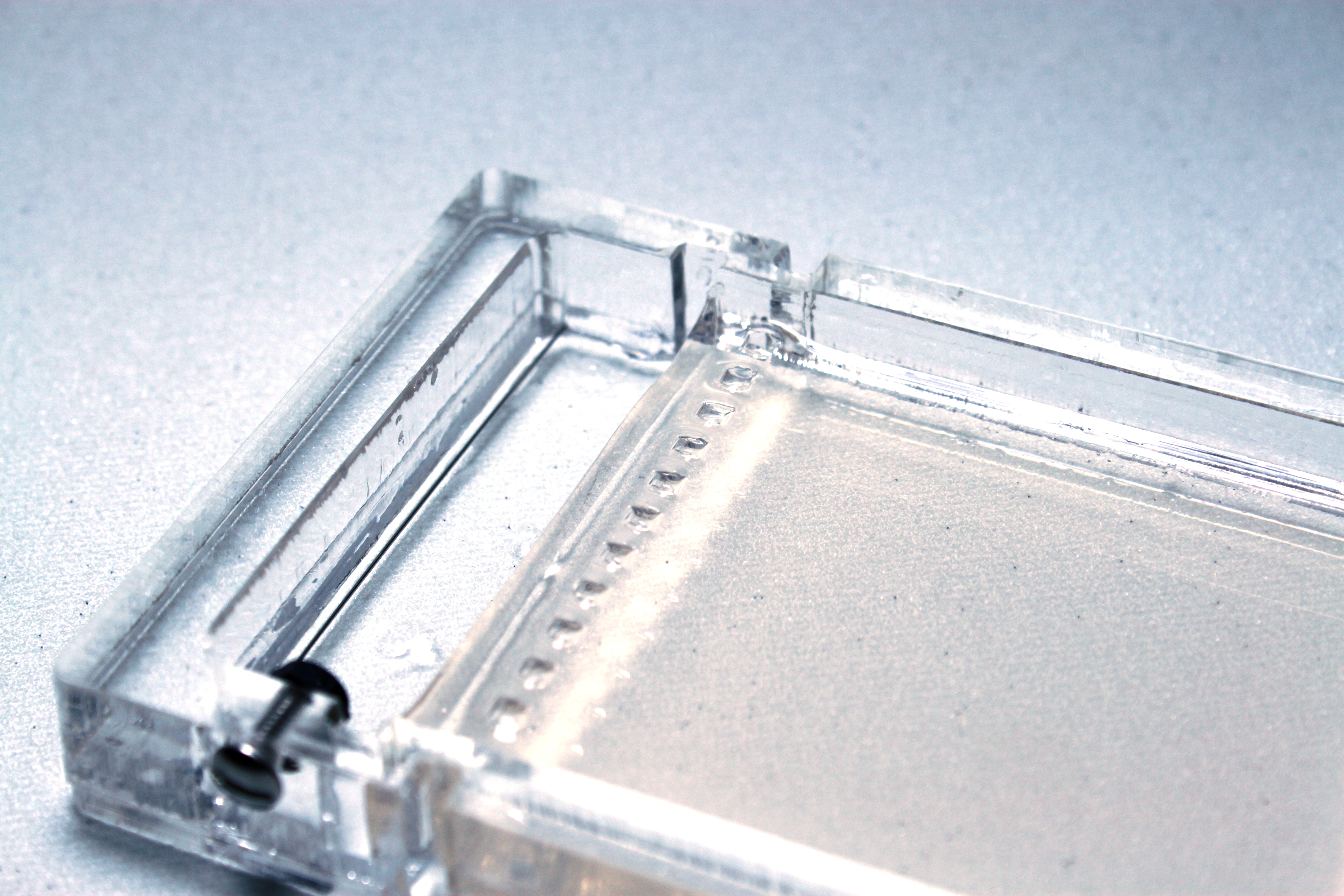
Here is a closeup of the gel and the electrodes.

Here is a closeup of the gel and the electrodes.

It is literally impossible to run this box backwards by accident, since you can only put the tray in in one direction.  If you wanted to run it “backwards” you could pull the electrodes out and move them to the other side, but otherwise your DNA will always be loaded on the right side.  The wells need to be wider and thinner, but setup for this part is slick and simple., and changing the width of the wells is as simple as cutting the comb out of thinner plastic.

IMG_4871

The bands on the top and bottom ran very evenly!

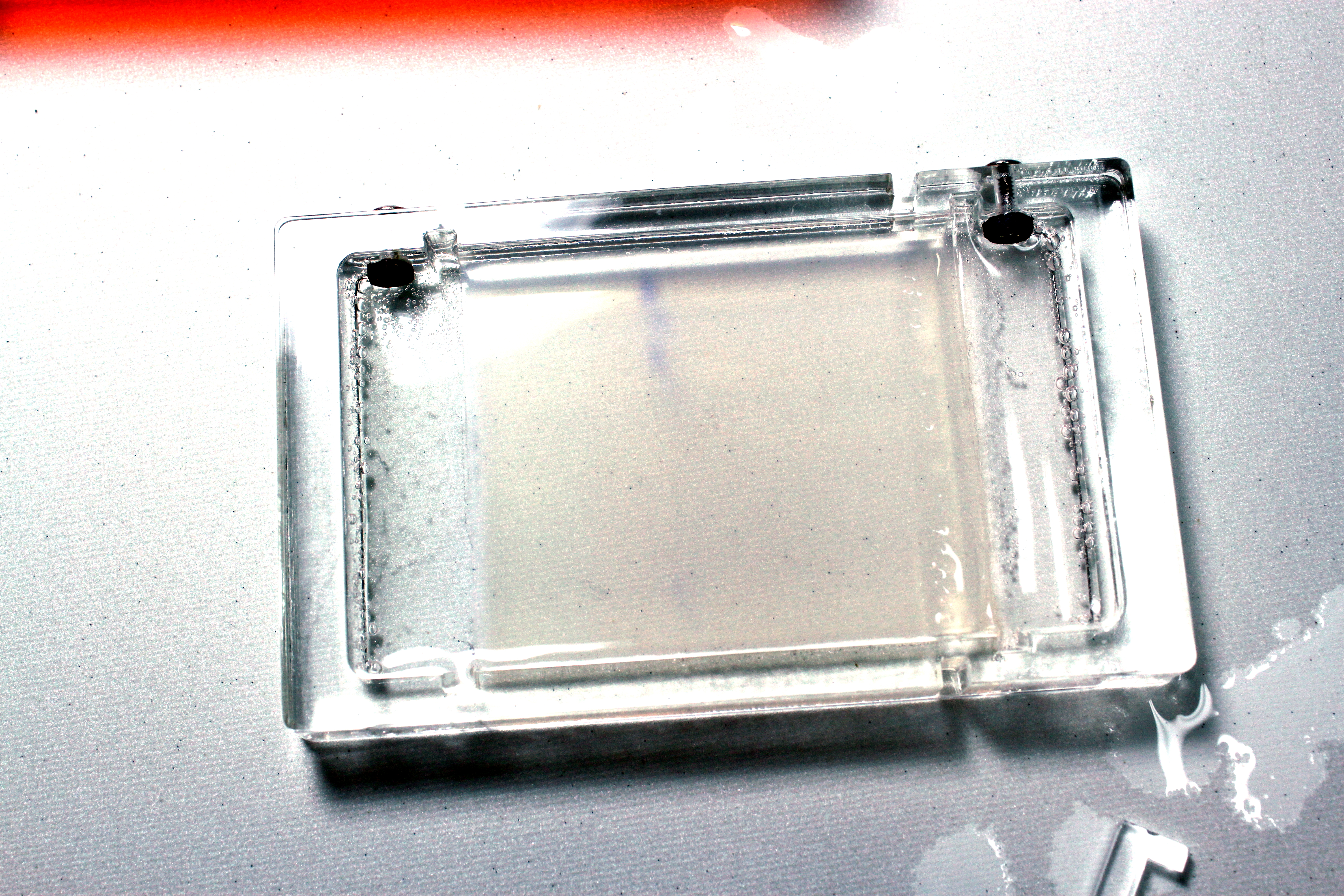
Here is the post-run gel, in regular light  You can barely see the loading dye on the bottom, since I didn’t quite get the sample in the well, but the lanes ran very evenly.

Gel imaging is hard.

Gel imaging is hard.

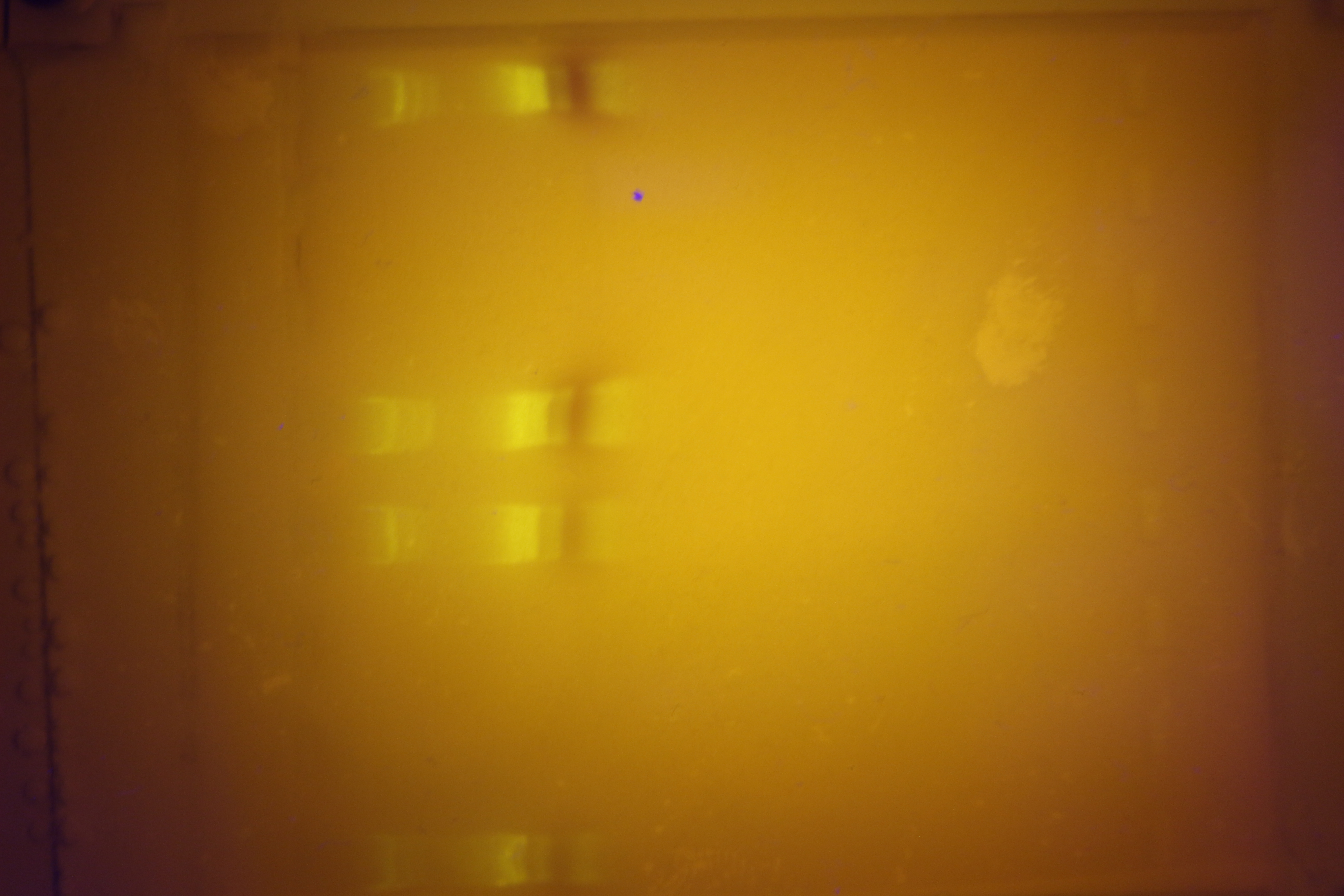
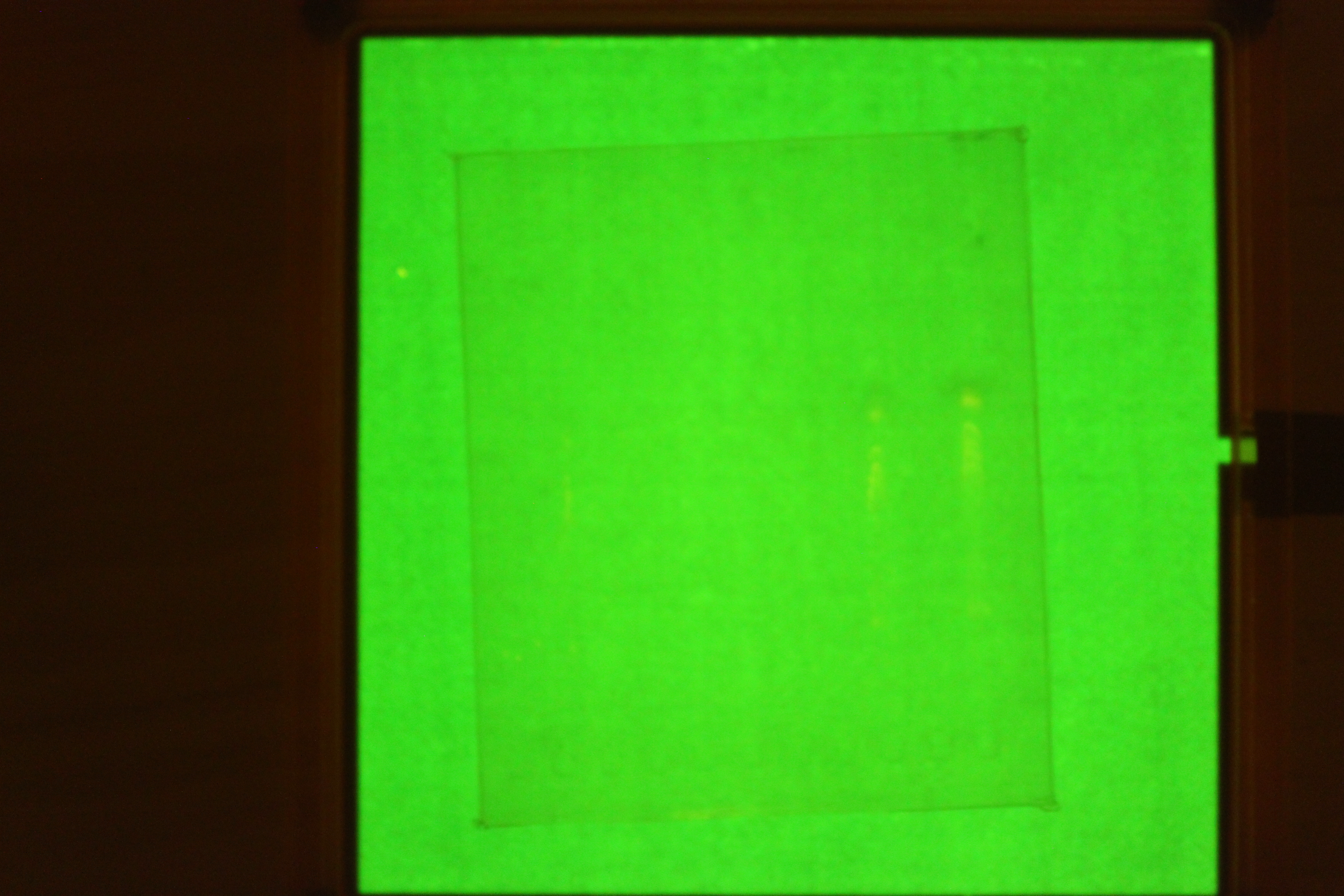
This picture shows two things: one, I might need a pre-filter if I want to do photography.  Two, you can barely see that the the gel did run, but that the sample wells need to be broader so you get the nice crisp bands that everyone loves.  In real life it is quite a bit more visible.  We will see what people want!

Overall, I  would call it a success.  A few tweaks need to be made on the units to be shipped out, but it’s time to try to get this thing out there, and have people use it!

GelIS Prototype Two, Fabrication Notes

The second prototype has seen large improvements in fabrication.  Other than the obvious problems, like the box being too small, there have been a few big improvements.

Spot the difference!

Spot the difference!  The left cutsheet should be missing the upper left hand portion, but that part was not cut because it was too large for the sheet.

On the left is the cut sheet from the previous prototype, and on the right is the cut sheet of the latest prototype.  The latest prototype is actually larger by square inches, but it takes almost half the time to cut!  And there is less waste of material between the parts.  The improvement here was manually aligning pieces to share edges, and then deleting (again, manually) one of the shared edges.  If you do this, deleting the extra edge is very important.  If you don’t the laser will hit it again, and sometimes create a very small “peel” of plastic between the two laser lines.  This piece of plastic is very thin, and will be insulated by air on post sides, which will cause it to catch on fire!  So delete the extra line.

IMG_4889

This is the “mouse door” cutout that lets you route cables with big connectors through small slots in mortise joints.  This one is still slightly too small, but it still works pretty well!

left, new box.  Right, old box

left, new box. Right, old box

I also changed the box configuration.  On the left is the new box, which is thinner and more affordable to fabricate.  It eliminates the on-edge holes, which I normally have to drill.  Originally I wanted to turn the tray on-edge and just laser cut the holes, but the cutter was not tall enough for that.

Thats all for this note!

GelIS: Second Cut

Image

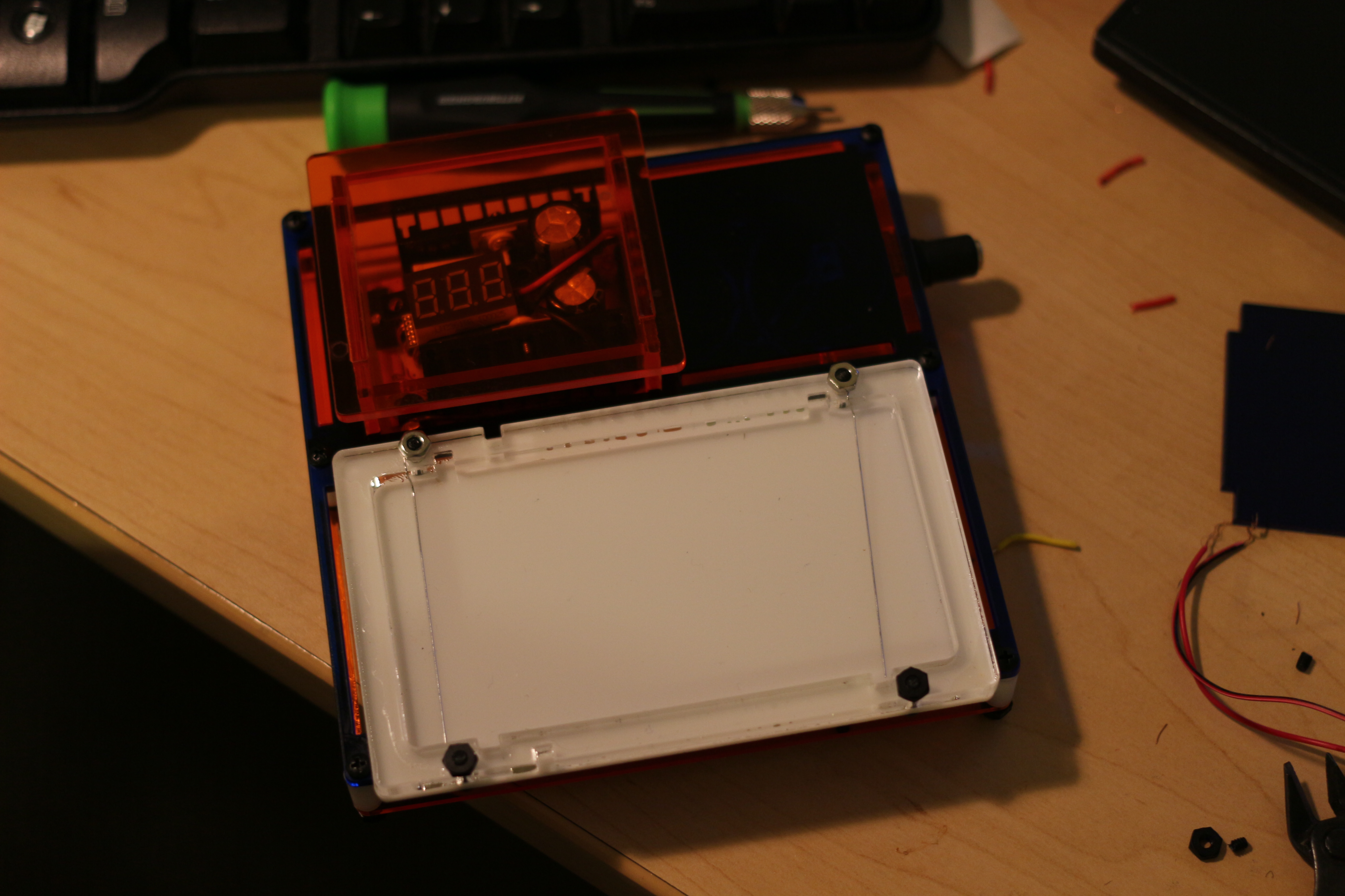
One more cut of the gel box.  It is looking really good, and there are only a couple of tight spots where the wires enter/exit the box.  It was assembled with only a screwdriver!  Tomorrow I will do a “wet test” of the system, and see how it fares.

DNA Sequence Allignment From Forward and Reverse Reads

The year is 2013.  Why is it when you Google “How do I align my forward and reverse sequences” the two methods that come up are using ClustalW (Clustal Omega), which requires a reference sequence, or some kind of awful witchcraft involving Microsoft word and the search function?  I guess there are also some programs out there that you have to pay a large sum to use (squencher etc.) but I certainly don’t have that kind of money.

X axis: number of base pairs overlapped from forward and reverse sequence Blue: number of pairs matching Green: "longest run"

X axis: number of base pairs overlapped from forward and reverse sequence
Blue: number of pairs matching
Green: “longest run”

So I decided to write a little python script to help me do alignments.  The output, which you see above, is not very user friendly yet, but it at least gives you a place to start before you devolve to microsoft word (of all things!  I will probably use libreoffice though).

Let me explain whats going on up there.  The script, which is called DNACrusher, takes the forward and reverse reads from your plasmid, and takes the reverse complement of the reverse read.  Then it overlaps the ends that should overlap (the end of the forward read, and the beginning of the reverse complement) by an increasing number of basepairs and counts two things: the longest matching run, and the number of matching base pairs, and stores them in a tuple that remembers how big the overlap is.

The blue line represents the raw number of agreeing basepairs.  As you would imagine, as you mash more bp together, the number of agreeing pairs generally go up, as does the noise on that read.  I haven’t computed any statistics, but that looks about right.  The only anomaly is right before 200 bp overlap, where you have a spike.  That turns out to be at 172 bp.

The green line represents the longest run of agreeing bp.  This line, as you can see, is relatively flat except for a corresponding peak at 172bp.  This makes me fairly certain that there is an overlap of about 172 bp, which seems reasonable.  When run against clustalW with the same sequences and a reference sequence, the overlap is about 160 bp, including some gaps in one strand or the other.

You can get the python at ye olde github account.  Included the two reads I used to create the graph above.  There are only a few methods in the little script, here is a breakdown of how to use them:

Import the DNACrusher module and pyplot

>>>import DNACusher

>>>import matplotlib.pyplot as plt

easy peasyImport your data from a Fasta File

Make a file object from your fasta file

>>>sequence=open(‘Fasta_File.txt’,’r’)

ta-da!

Convert Your File Object to A String

>>>sequence=DNACrusher.fasta_to_string(sequence)

now sequence is a string, which is way easier to deal with

Reverse Complement

>>>sequence=DNACrusher.reverse(sequence)

>>>sequence=DNACrusher.complement(sequence)

‘atgcaata’->’tattgcat’

Overlap N Base Pairs

>>>DNACrusher.crush(forward,reverse,N_BasePairs)

This will return the count of matched bps and the longest run of pbs in a tuple (count, longest)

Overlap Up to N Base Pairs

>>>align=DNACrusher.allign(forward,reverse,N_BasePairs)

This will return a list of tuples [ (pairs_overlapped,(count,longest) , …]

Now to Plot It

>>>plt.plot([ x[1][0] for x in align])  #plot the number of agreement

>>>plt.plot(x[1][1] for x in align]) #plot the record # of runs

>>>plt.show() #show the graph!

Now if you do this with the sequences I provided, you should see the above graph!

>>