Mo’ Moped Repairs.

Fixing my moped!

I will preface this story with two statements:

  • I should have known better
  • I should have brought my camera

The other day I bought a puch clutch cable from treats, thinking “YAY! The end of my clutch worries!”, but I was oh-so-wrong.  After obsessively checking the tracking, I rushed home to find a new clutch cable, knarps, and jets!  However, the nubbin on the end of the cable which had looked quite substantial on the Internet, was naught but a teeny piece of metal, no bigger than about 1mm around by 3mm long.  I’m pretty sure the puch uses the much larger toggle-shaped nubbin on the other end of the cable.  But I figured that they sold it as a starter cable, so it must work…right?

So I installed the cable and knarp, removing the bicycle shifter cable that I had previously wrapped around my clutch lever (being knarp-less at the time).  With that done, I got to work on the carb, removing it from the engine by loosening the screw on the clamp that holds it to the intake.  Of course, this meant that gasoline got EVERYHWERE, but being a moped there were only a few ccs in the float bowl.  A few clicks later, the float bowl was removed and I had access to the main jet!  I screwed the old, corroded, nasty jet out and replaced it with a fresh 50 jet.

Fast forward through carb re-assembly and attachment, fuel line replacement, and stopcock opening and I was down on the street to test it out!  I pulled on the clutch lever, and heard a small *pop*.  That pop ended that nights work, because I knew from the slack on the clutch lever that the teeny tiny nubbin had snapped off into the clutch assembly, and that the last thing I wanted to do was to grind up a tiny piece of metal with my clutch/trans, and flood the system with tiny pieces of metal to get stuck in bearings.  So I walked it to where it normally hangs out, parked it, and called it a night.
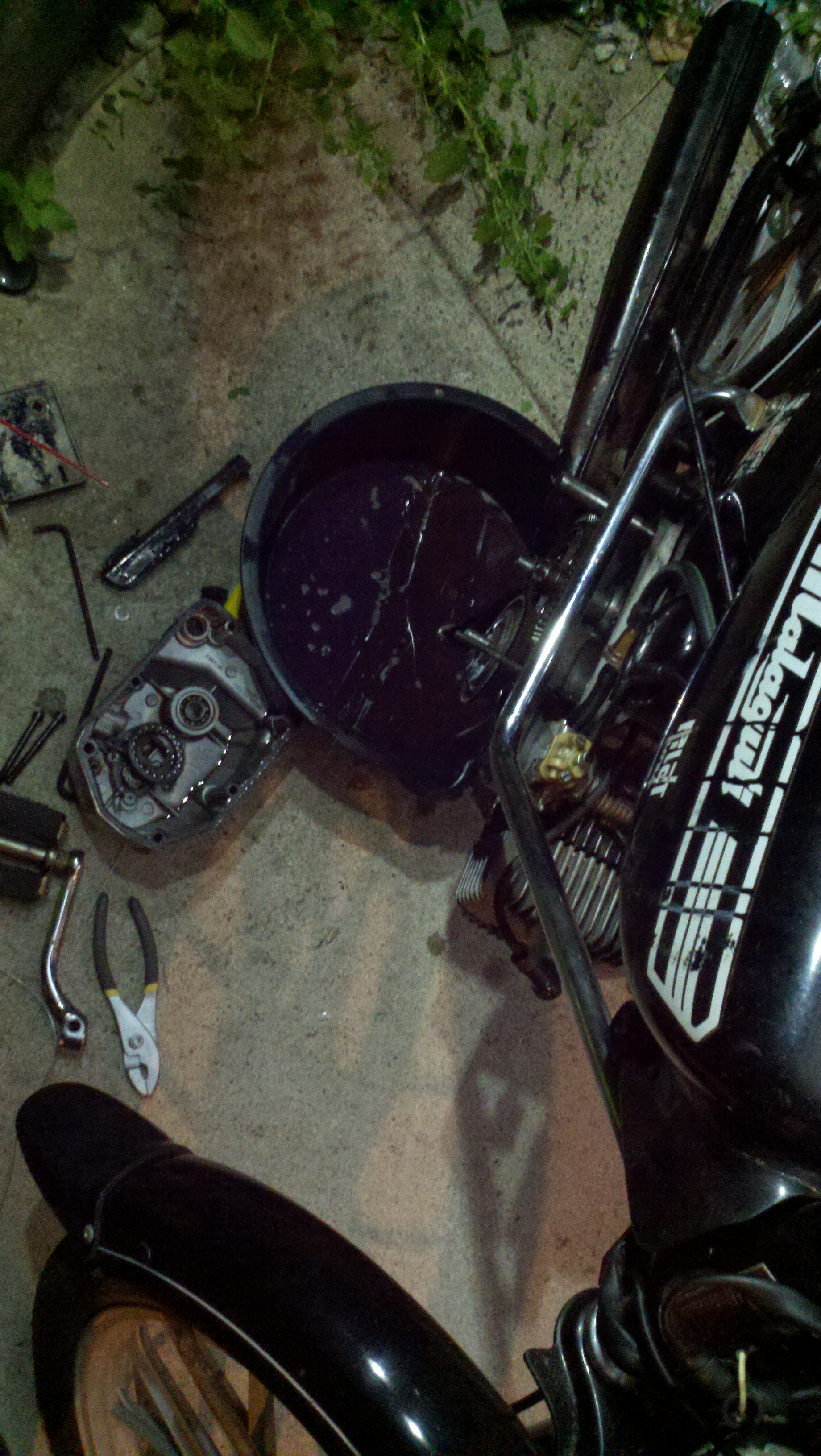
Another night of moped work. Goo everywhere

The next day I was back to working on the moped.  It was really frustrating to have been so close to testing the new jet, and then to have the clutch lever break AGAIN.  Especially after I had a hunch that it would break in exactly the unpleasant way that it broke in!

The first step, of course, was to tool up.  I grabbed an oil pan and funnel from my local (and very friendly) Tags, and some 30W ND SAE oil from, of all places, Family Dollar.  Then it was back to the moped to take apart the clutch/trans.
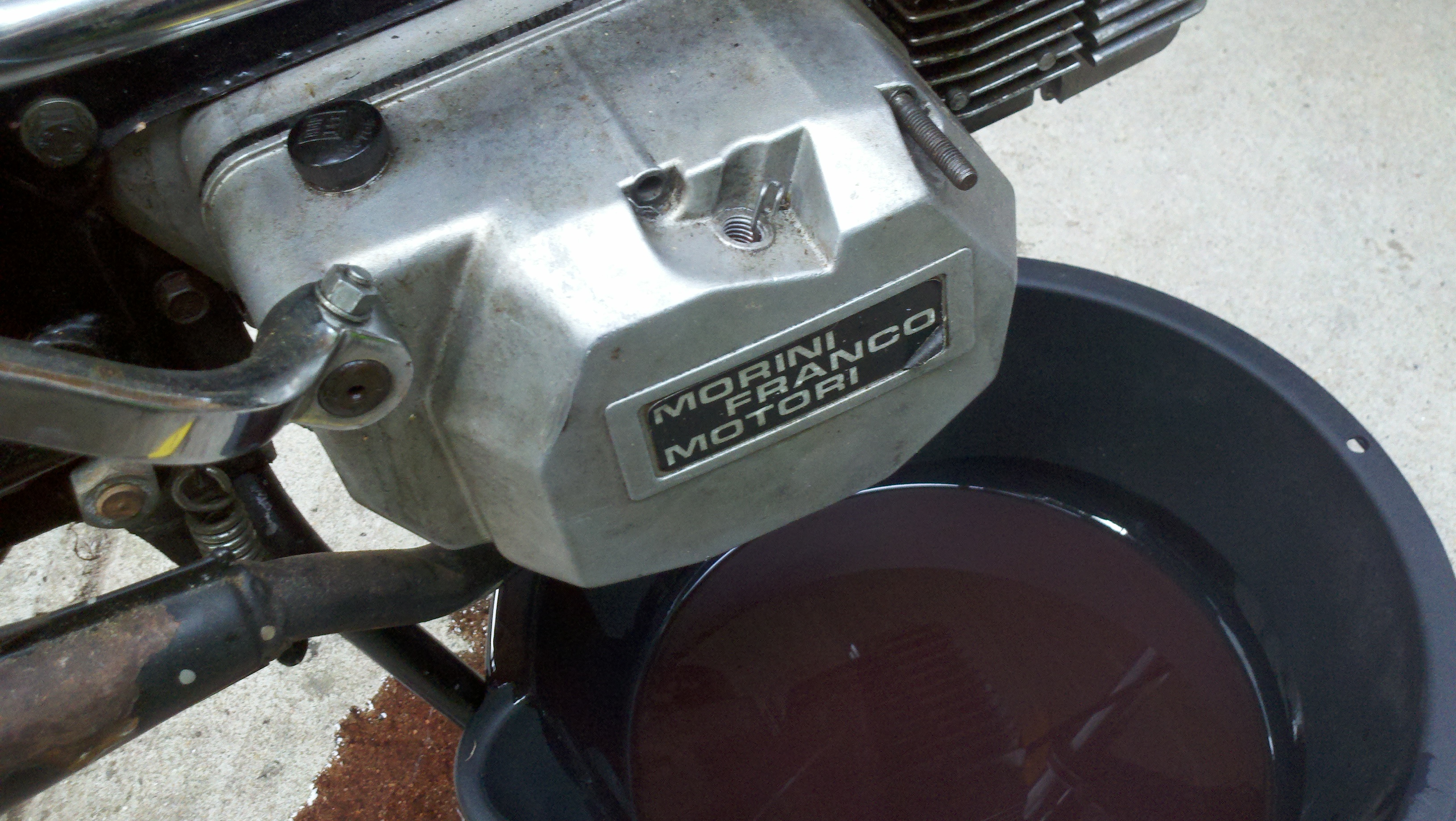
Oil everywhere! Next time I will drain the oil out with the bolts that are specially made for draining the oil out…

The clutch happens to be lubricated by being submerged in oil.  So as soon as I popped the last screw off, and pulled the clutch housing off, a huge purple puddle of oil appeared under the ‘ped, mostly in the oil bucket (yay foresight!).  Unfortunately, the teeny nubbin did not come out with the oil, and without removing the pedal arm the case was still stuck on pretty close o the engine casing.  So the next step was to try to wash it out with more oil, and hope for the best.

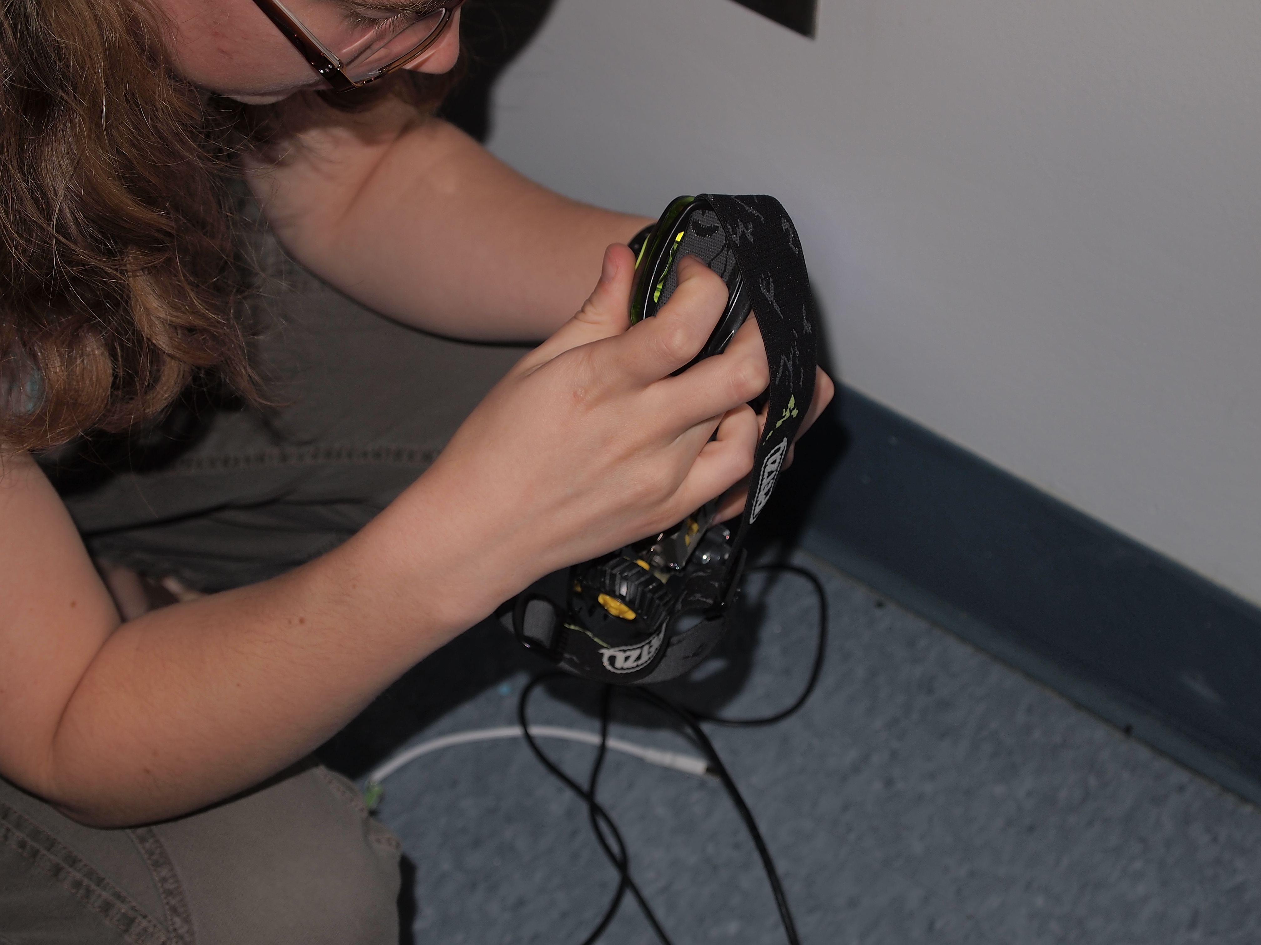
Bright LED lights. Don’t look at these; they will blind you!

Unfortunately, no combination of smacking the sides, running oil through the clutch, and grunting would coerces the tiny piece of aluminum to come out.  I even tried to locate it visually by sticking a handy strip LED flashlight near the gap in the case, and looking through the clutch hole.  But at this point it was getting pretty dark, so I wired up some huge LED panels (40W of them).  They did the trick!  I was set to work as late as I wanted.
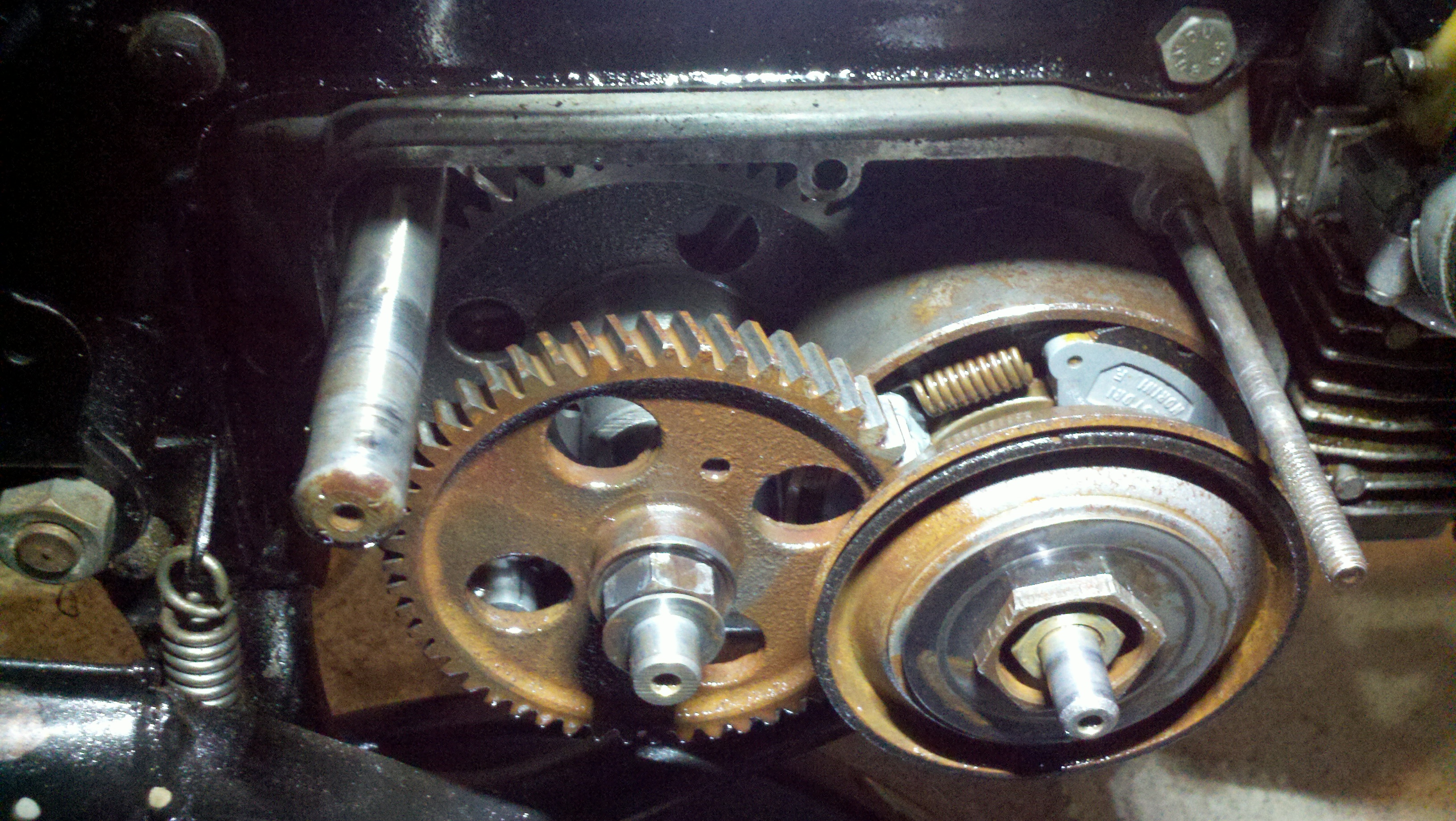
The clutch of the morini m02

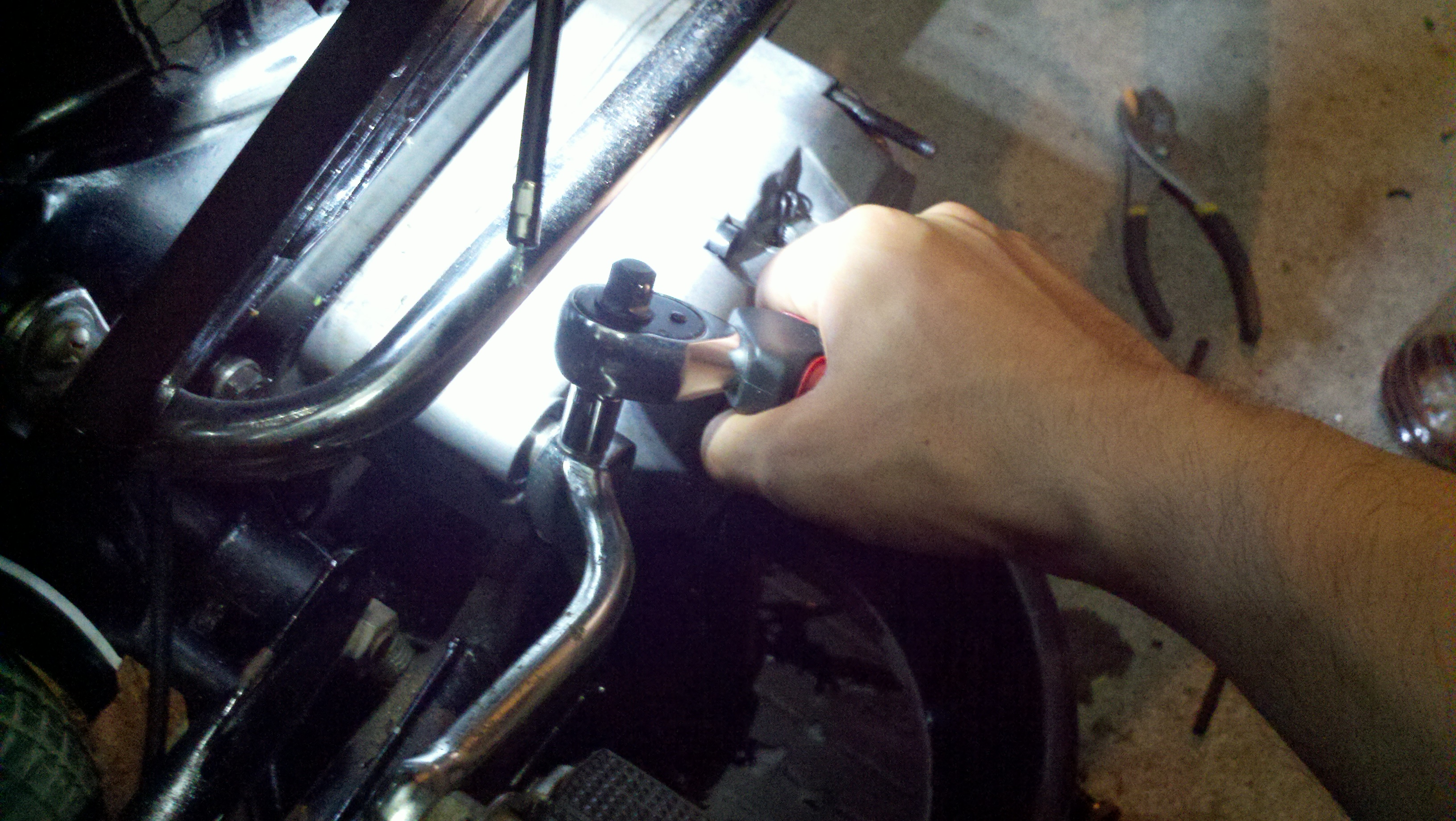
The pedal needed to come off so I could completely remove the engine casing.  The pedal is held on by a wedge that his hammered in, and then a bolt is tightened to the other side to make sure it does not rattle loose.  Unfortunately, to remove the pin you have to smack the threaded side pretty good, and the pliers I were using to tap it out were not cutting it.  The next best thing, since I didn’t have a hammer, was to give it a good whack with an old lever lock.  Eventually, as my frustration built, I managed to whack the peg hard enough that it budged.  A few more taps and it was loose in my hand.  Moments later, the pedal arm was removed and the clutch cover followed soon after.  Unfortunately, this stripped the threads on the wedge that holds the pedal on.
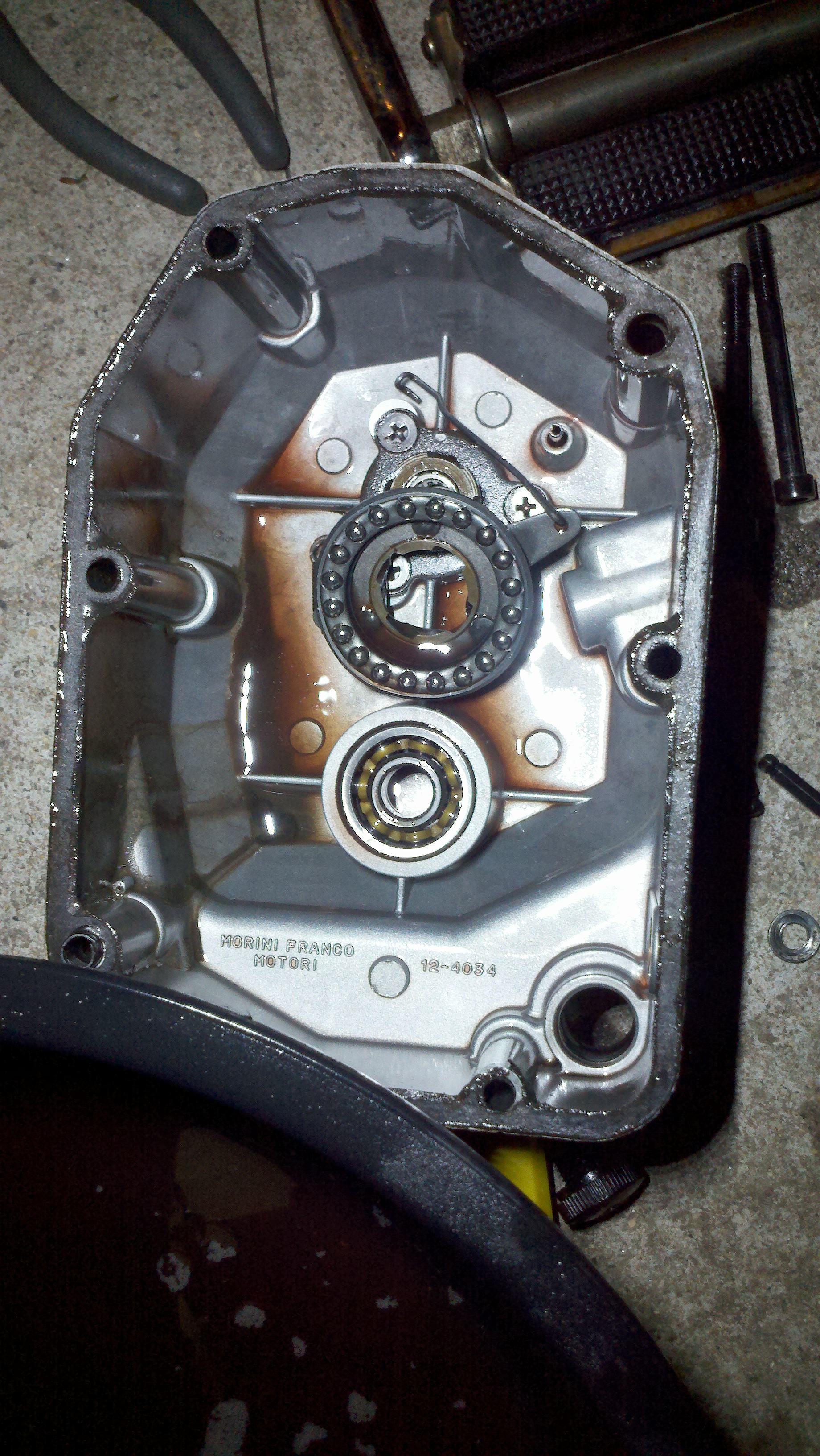
Clutch case and some bearings that came out with it! If you look hard you can find the nubbin next to the lower left bolt-hole casting.

With the clutch cover removed, it was easy to find the nubbin.  It had gotten stuck in a corner of the casing, in a bit of oil.  I grabbed it, and a few other offending bits and bobs out of the clutch casing.  After that, I returned the casing to its proper position, and bolted it back on.  Then I chased the threads on the pedal wedge with a file, and managed to bang it back into place.  The last thing to do was to fill it with oil, and then wire up a clutch cable in the form of a new bike shifter and a knarp.

With all of that done, it was time to test the new jet!  I took it out to the street, carefully engaged the clutch, and got it to start and idle, but only for a few seconds.  Based on the bumpy ride, I think the jet is too big.  However, it was a good day!  Things were capital A Accomplished, tools were improvised, and actual progress was made!
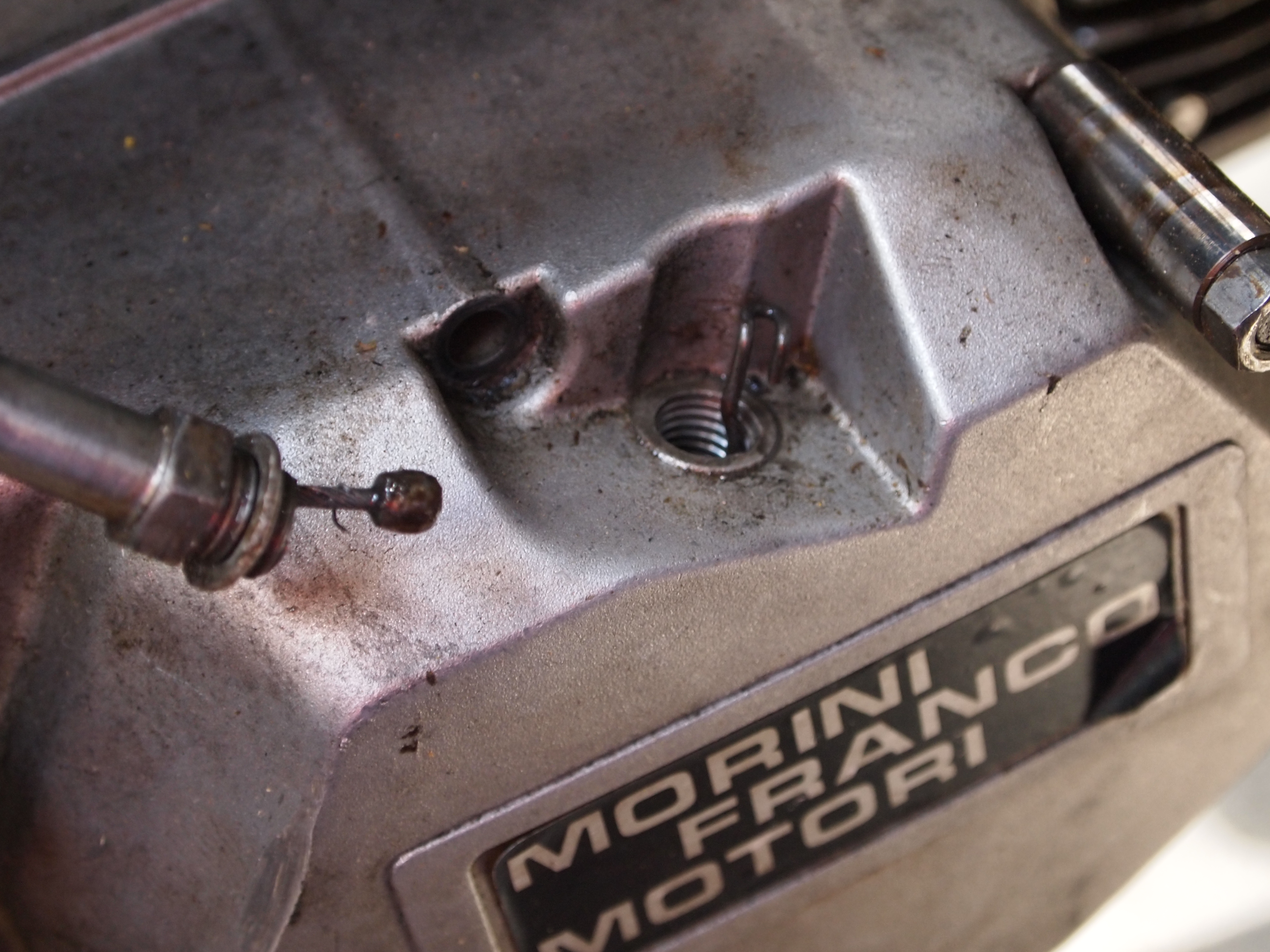
Morini MO2 Clutch Cable Replacement

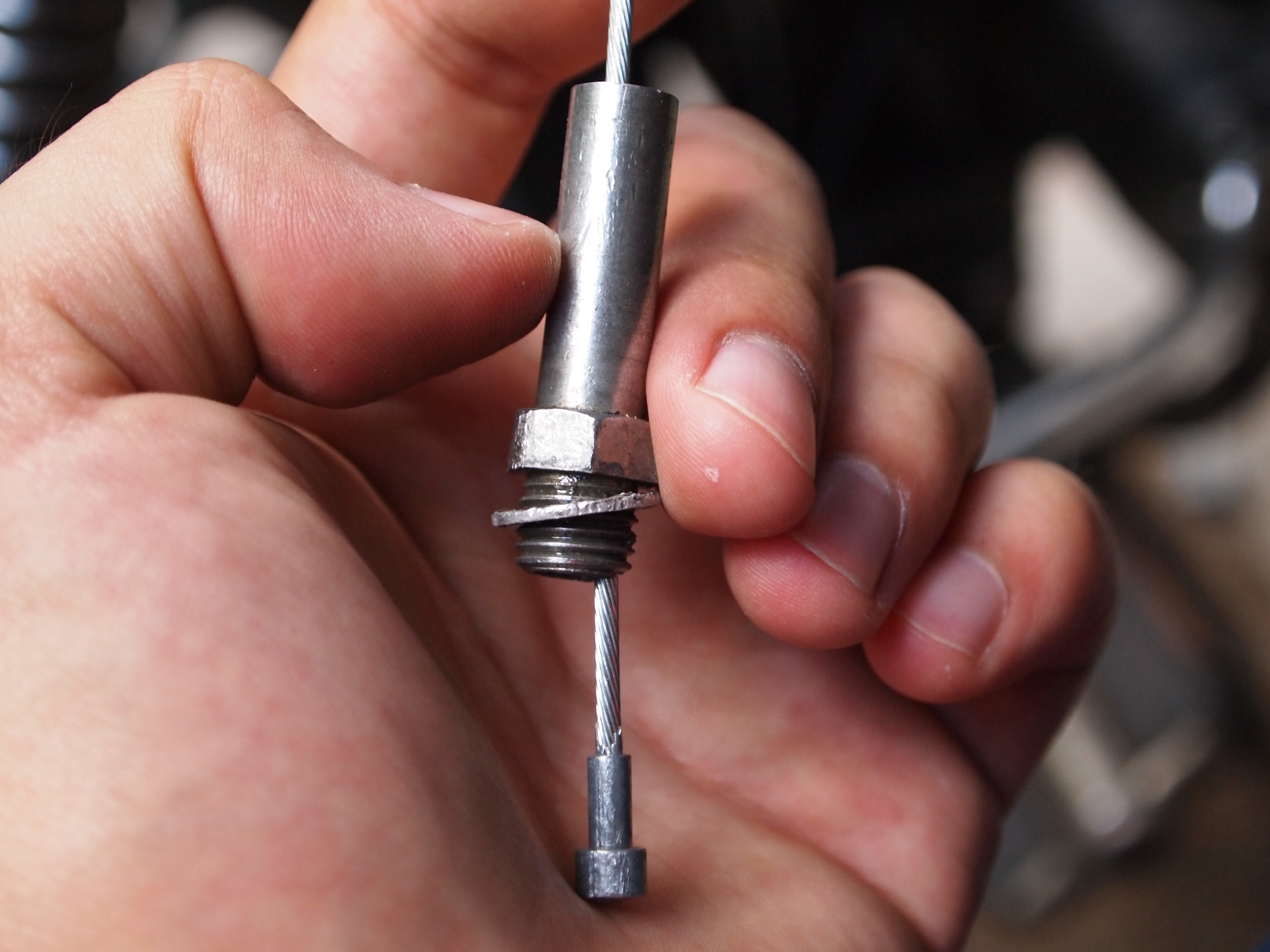
The right kind of clutch cable for an m02 morini, and the clever little clip that actually engages the clutch.

So I snapped the cable off the clutch lever of the Pilot the other day, and as a result, I went to San Fransisco to buy a new clutch cable (not really for that, but I did go to SF and get a clutch cable).  When I got home, I discovered two things:

  1. The people who designed the bike were not stupid
  2. I bought the wrong kind of cable!

The wrong kind of nubbin!

Grr.  The extra little bit above the very end nub prevents it from being able to be pulled, since the bottom nub makes the clip coming out of the engine rub against the guide.  Unfortunately, I had not removed the guide all the way and really given the system a peek until after I had bought the new cable.  Fortunately, a bike shifter cable is the perfect size, looks to be pretty strong, and is available in abundance in Somerville.  After picking one up, I managed to rig it up so that it can sort of engage the clutch.  It is tricky to get it engaged, but for the time being, yay testing!

Malaguti Update: 6/7/2012

Got the ‘guti running!  Good stuff.  Vroom vroom.  Or maybe like, vrrrr….

I hope I look this good when I turn 40!

There are still a few slight issues, but I got it to run by adjusting the spark gap with some .4 mm metal sheeting, which I found at sprout.  I think it is for weather proofing.  The other suggestion for a feeler gauge stand in that I got was a cereal box, so the piece of metal seemed like a decent option, given that it measured .34-.41 mm on some digital callipers, and the gap should be .35-.4 mm for a Morini MO2 (M02?) engine.

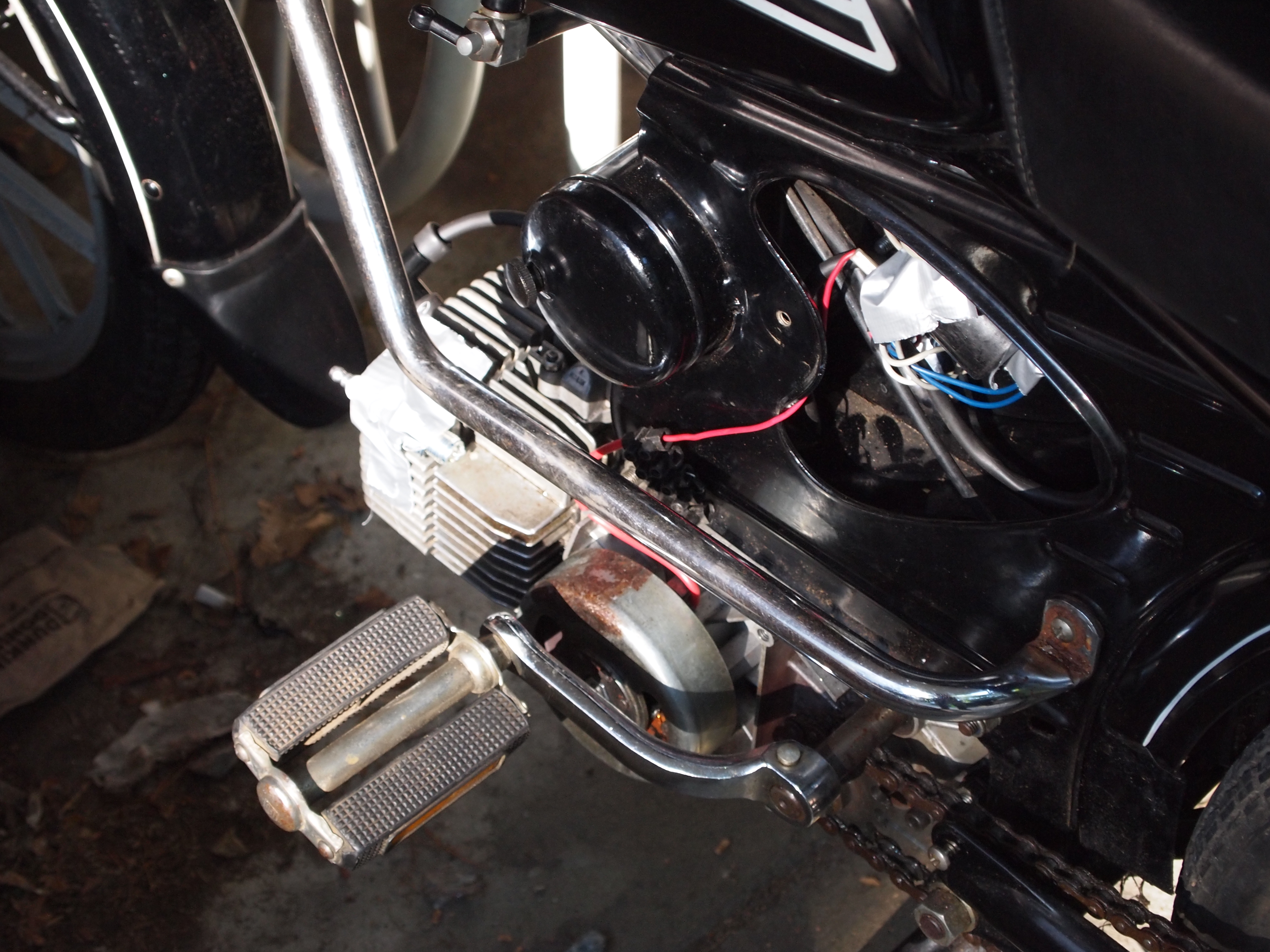
A picture showing the electrical SNAFU

Outstanding issues are now that the electrical system is in a small SNAFU, because I hard-wired EVERYTHING, disconnected the killswitch, the tail light is broken, and the lighting coil is not tested or installed.  Also, the carb needs to be re-jetted and the idle adjusted, since it was drilled out by the previous owner.  And the last thing is that the clutch cable broke!  Oh no!  Better go to treats.  Oh, yea and the pipe is clogged.

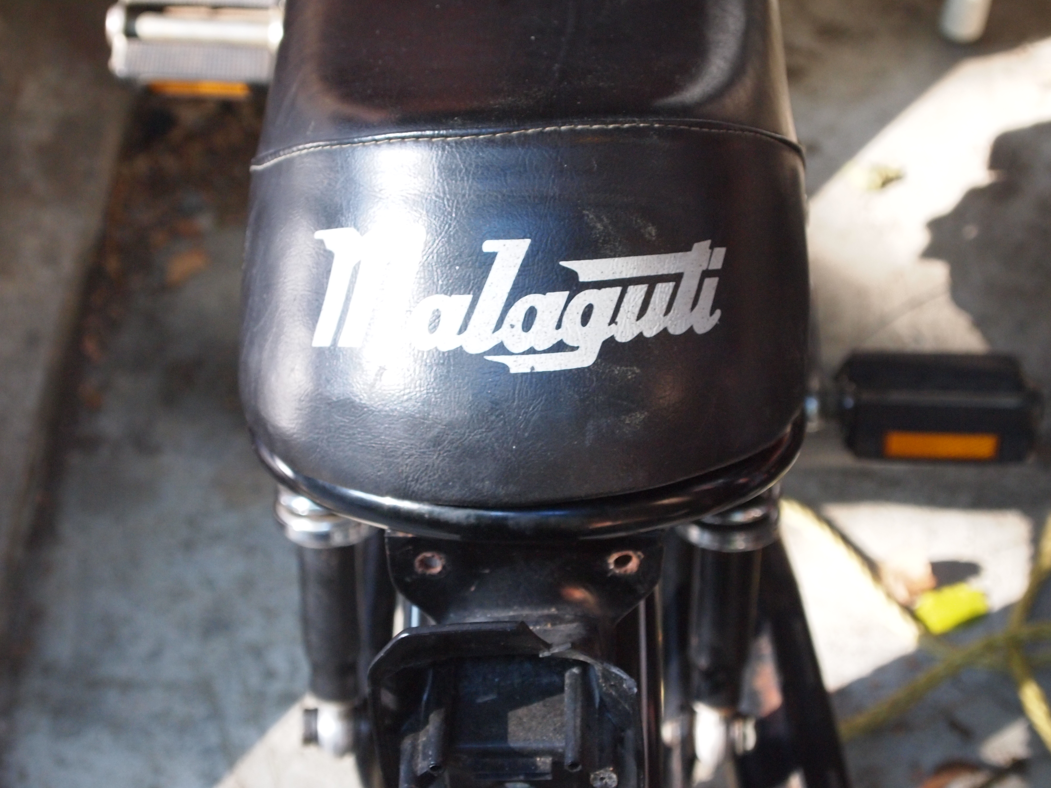
Whats missing? The tail light is missing…

Other than all that, I got it moved to the new workspace okay by yanking the clutch cable real hard with my left hand, giving it gas with my right hand, and peddling really really hard.  I got all the way down one or two blocks before I ran into a one way street in the other direction and the engine died again.  Bugger.

Malaguti Pilot: A New Project

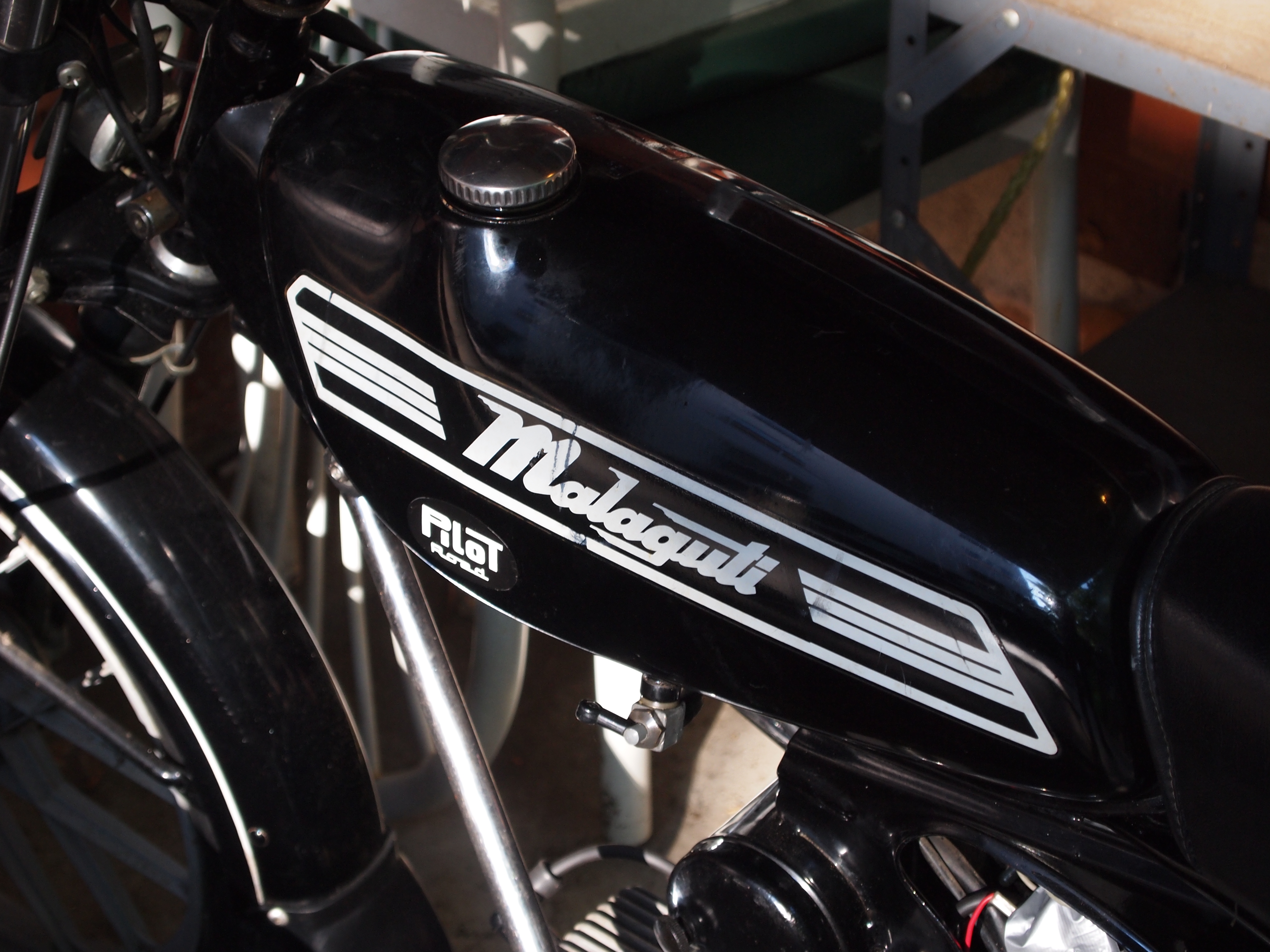
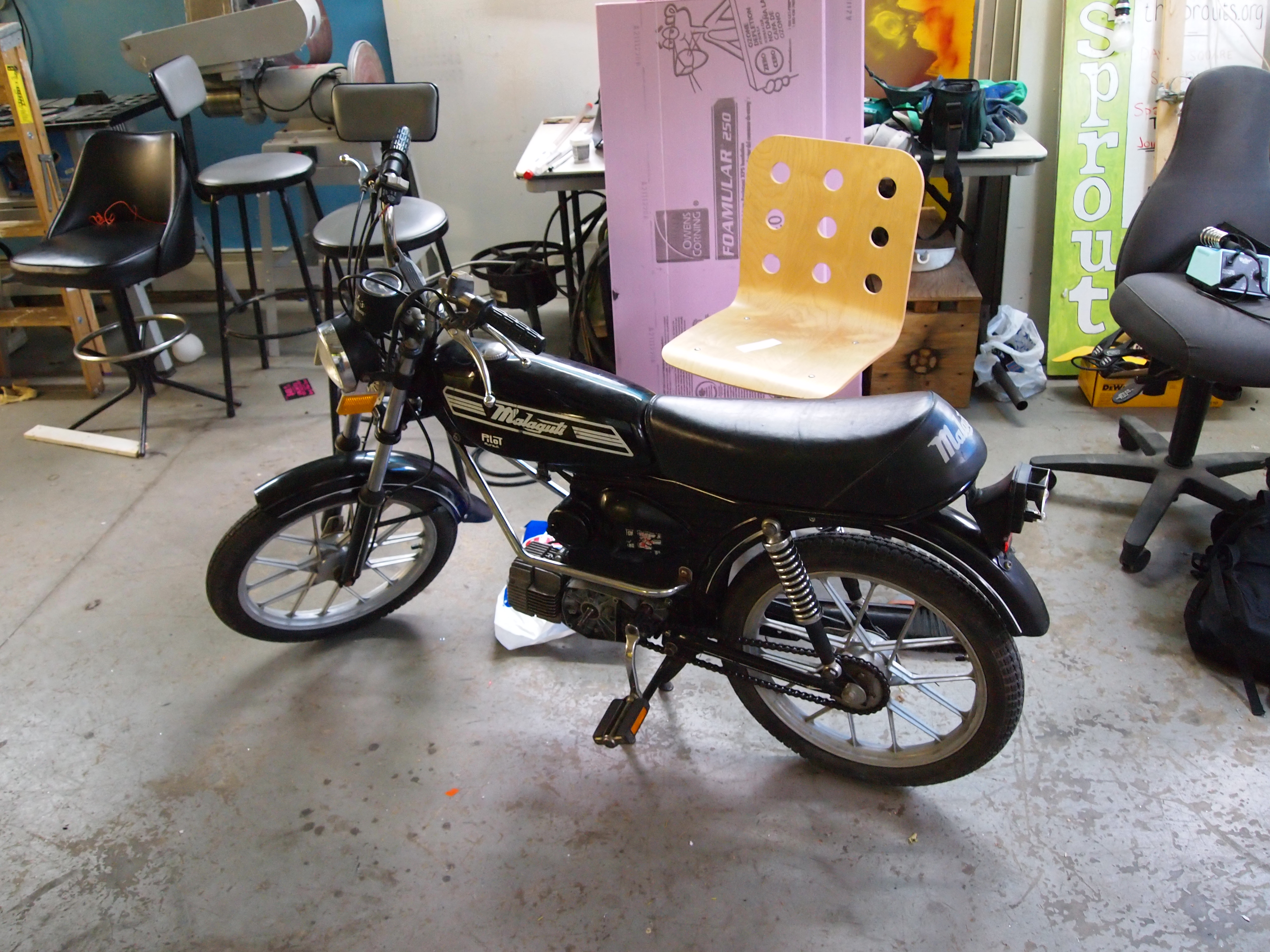
The ” ‘guti “, a malaguti pilot from the 70’s

I picked this moped up from kHz Garage in Allston- not running in its current condition, but with a few donor electrical and fuel related parts, it had started up, according to the previous owners.  I pedal/push/pulled it all the way from allston, up through Harvard and porter square to sprout to sit down with it for a few days to get it repaired.  It was a long and very exhausting trip, but the next day I got to look at some of the things that were not functioning.

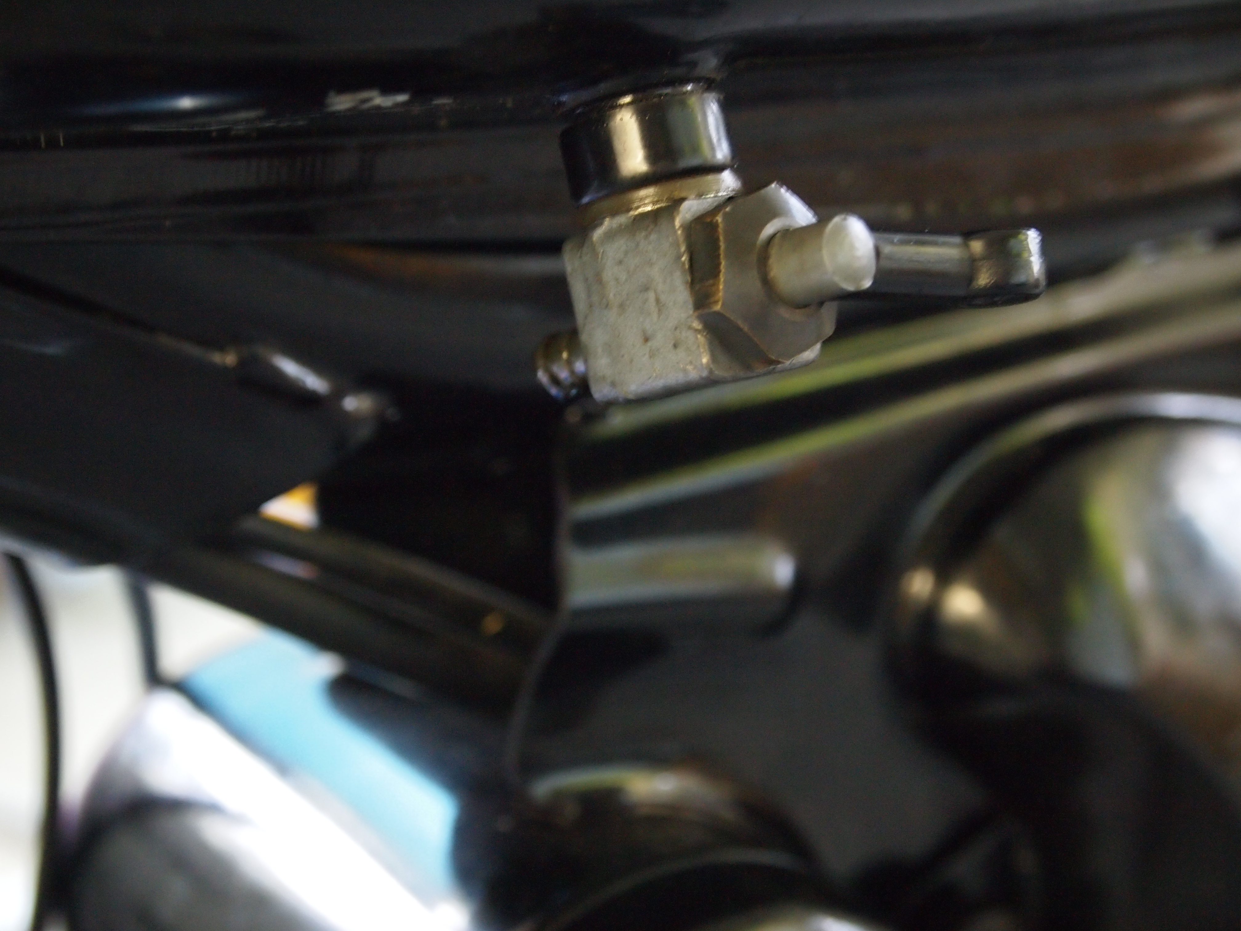
Something is missing here…

Something is missing here.  Some kind of tube to convey liquid fuel (gasoline+2 stroke premix) to the carb.  Ah, a fuel line and fuel filter are in order.  In short order, the magic of 3/16 in (4mm, I believe) fuel line and a cheap, $5 filter fixed this problem.

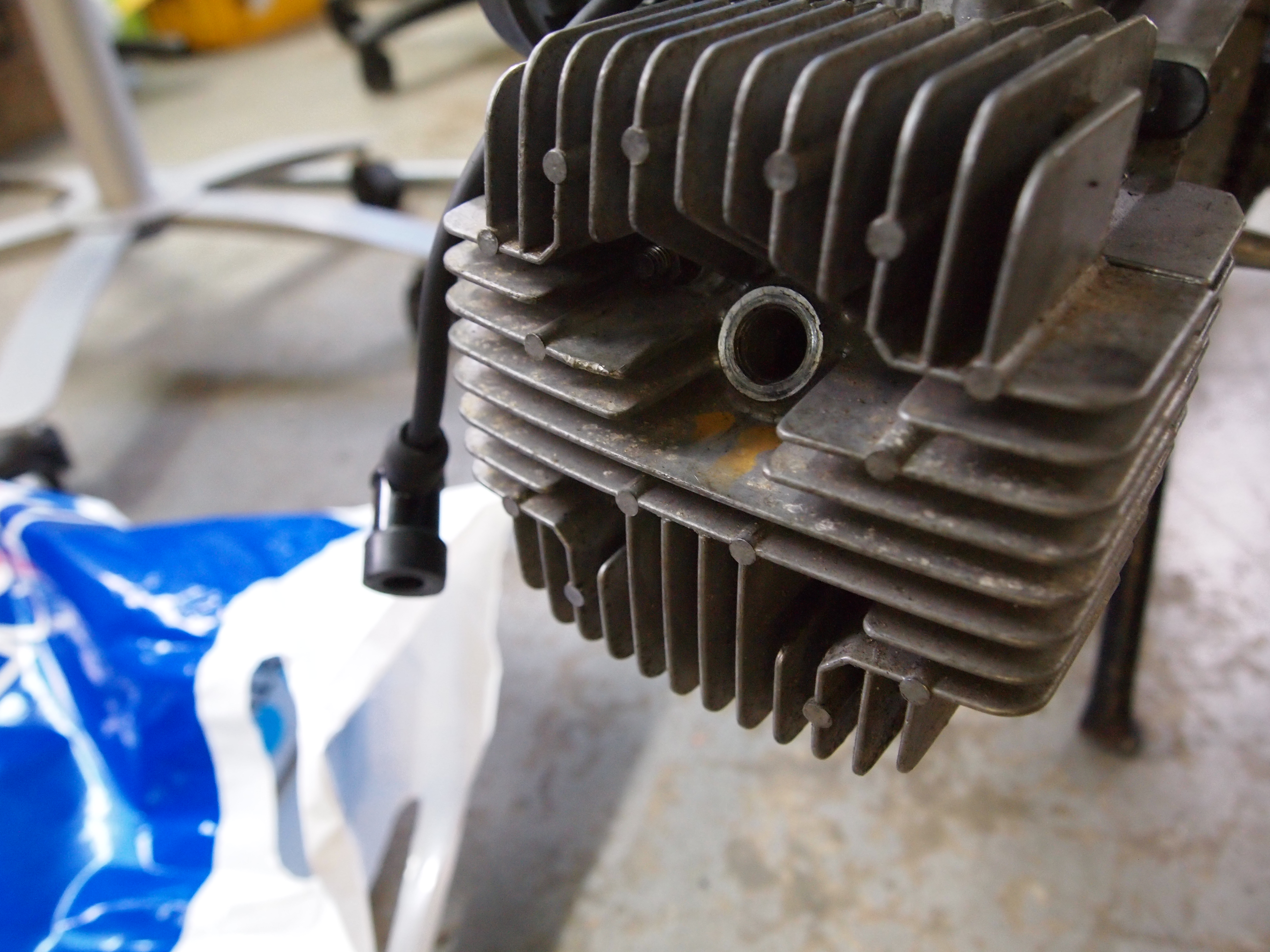
Something is missing here too! What could it be…?

I got a new spark plug boot as part of the bike, but I needed some B6HS spark plugs for the Franco Morini Motori MO2 (motor).  So I got some and installed one.

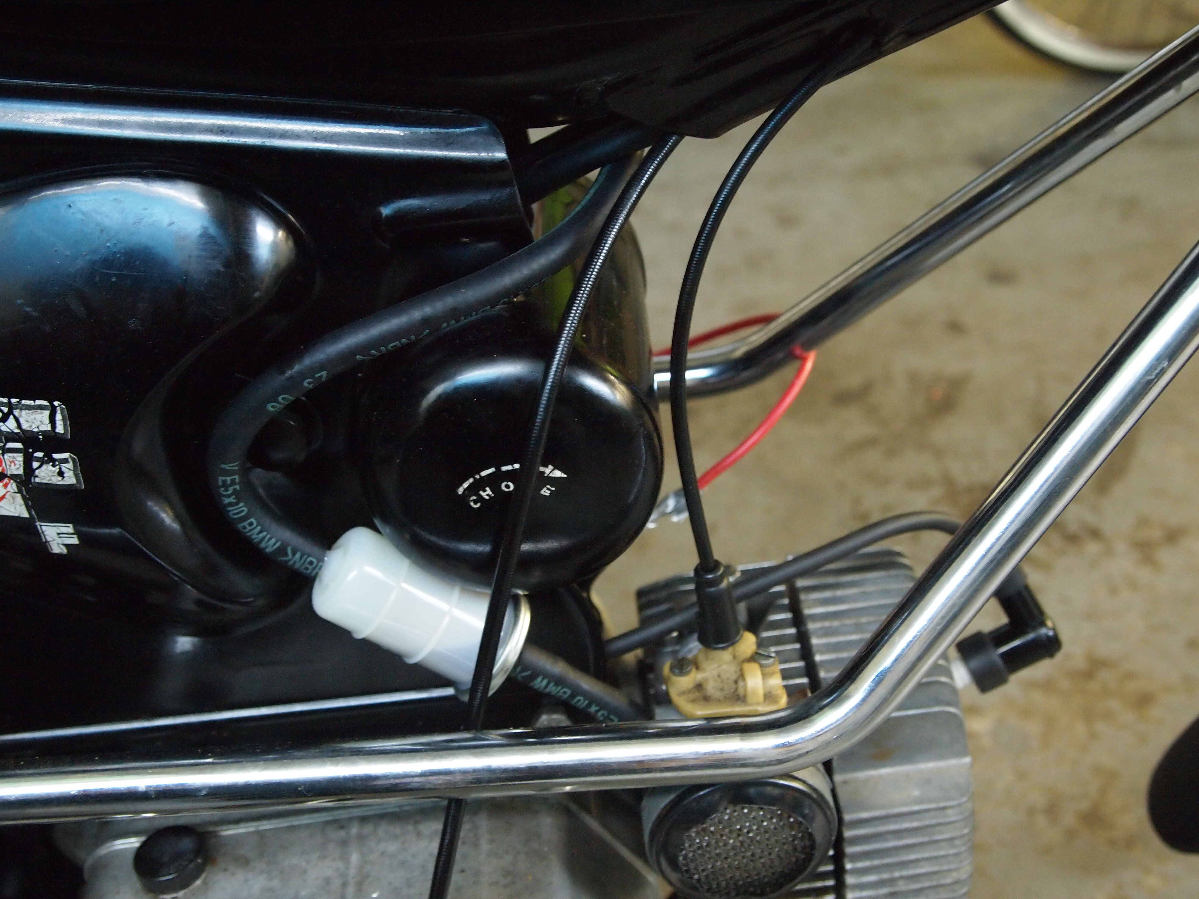
fuel line and filter routed around stash box


Here you can see the fuel line and filter mounted around the stash box, near the side panels of the body.  The stash box is pretty sweet- it looks like a good place to stash some extra fuel line, a fresh plug, or maybe some small tools.  In the background you can see the spark plug mounted at a funky angle.  Way Rad!

Well, that is all for now.  There is no spark since I still have not wired the magneto yet- once I do that it is time to test the whole system!

How Do I Get Started In DIYBIO?

A lot of people have been asking “How do I get started in DIYBIO?”.  The answer is not easy.  Biology is a broad field, ranging from studying entire ecosystems, to the chemicals that allow life to continue.  But I have done my fair share of DIY molecular biology, and I have begun to write up protocols and reviews of equiptment- which I will begin to share on this site on the DIYBIO protocols page, and on BOSSLAB.

Enjoy!  More posts on how to get started to come.

Gene Cloning: Successful!

Today, amid the project crises going on for my various classes, I got some very good and very exciting news:  my engineered microbial systems project seems to be going well!

A little background on the project and team:

Our team consists of three people:  Neal Singer (MechE), Jea Young Park (E:Bio) and myself (MechE).  Our professor is Jean Huang, who is awesome and exceedingly good at juggling multiple projects and inspiring us to do cool things.  The goal of our team was to (in the span of a month), clone a gene from p. Atlantica into e. Coli.  It sounds like it should be simple and routine, but it is actually quite a process.  The good news is it seems to have worked!

How do we know it worked?  Check out these gels:

This slideshow requires JavaScript.

The “top” of the gel is side with the wells closest to the edge.  From left to right, we ran the PCR products from samples of plasmid from transformants in wells 1-9, and the 10th one was a positive control of PCR product of genomic DNA.  The idea is that if the plasmid contains the gene, we would see a band near the positive control which definitely contains a copy of the gene.  And the result is that we do!  This means that when we ligated the plasmid and the newly cloned gene, some of the copies re-circularized without the gene, and some of the copies incorporated the new gene, and some of those copies of the gene ended up in bacteria that we have growing in the lab.

Sweeeeeeeeeet.

REVOBOTS 5/6: The end of the REVOBots Story

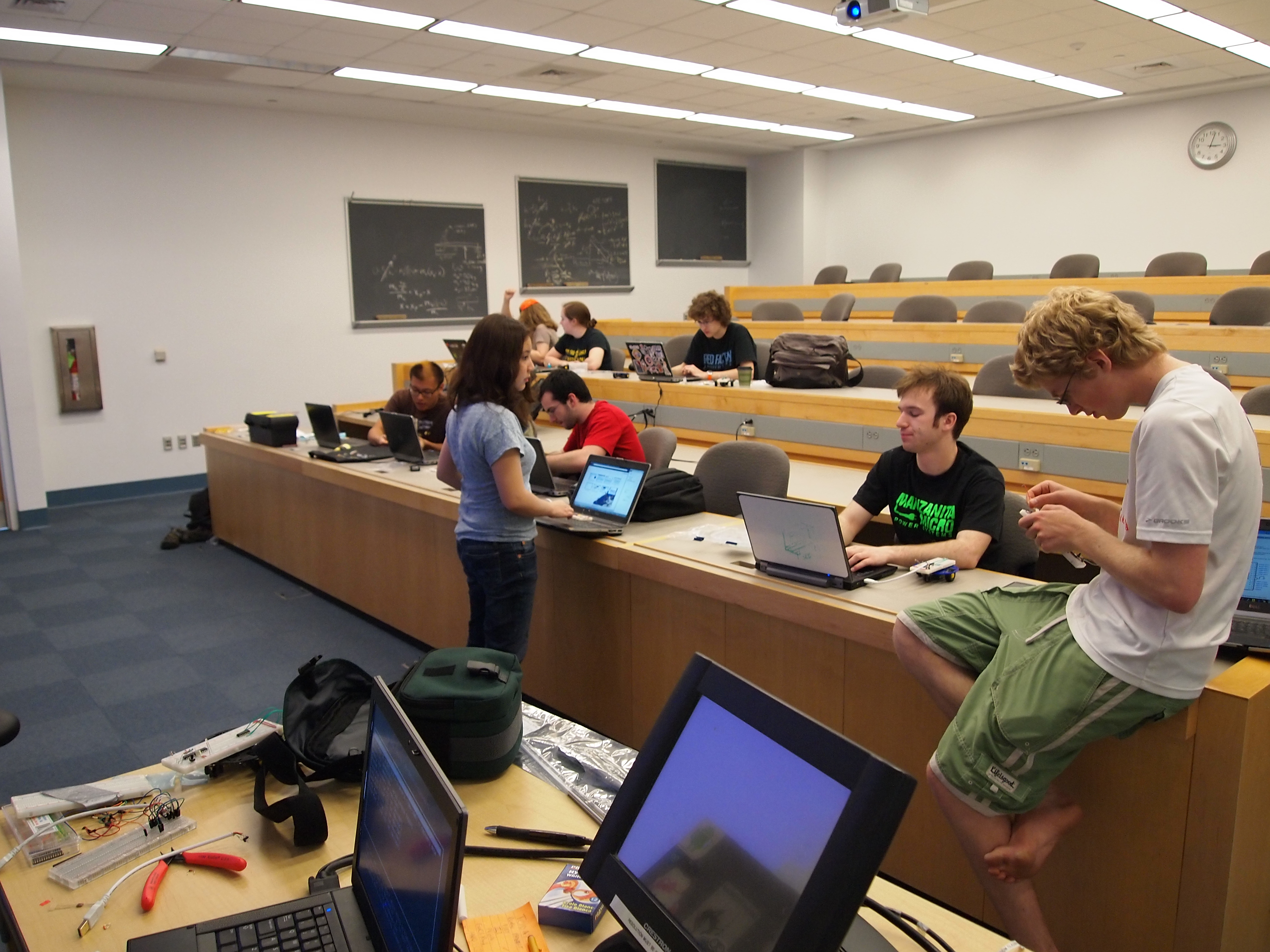
Students in REVOBots

For schematics and code, check out the revobots page here.  For video of the bot, look here.

Well folks, it is about time I wrapped up REVOBots, which turned out to be just as much work as expected; which is to say that it took more time and effort that I had planned.  And as expected, attendance dropped off towards the end of the semester as our project based classes go into full swing and spring (and the opportunity to lounge around outside) starts to warm up the weather.

REVOBots 5 ended up being an explanation about some code that I wrote, and an introduction to EagleCAD.  I have attached the code to the revobots 6 pdf because if fits in better there.

A student testing a ‘bot in the dark

REVOBots 6 was a build day dedicated to making the revobots go.  There were two critical failures on my part before revobots 6:

  • Did not spec out the motors/H-bridges properly.  The motors turn out to run at 3V, while the H bridges run at 5- ~30 V.
  • Did not order parts early enough

That said, the bots still work at 5 volts, albeit with a drastically shorter motor life.  But operating at 5V this seemed to cause too much of a current drain on the power supply, so we got some weird twitchy behavior during the class.  Since then I have developed a cheap fix using two 2n3906 NPN transistors, and a smattering of decoupling caps.

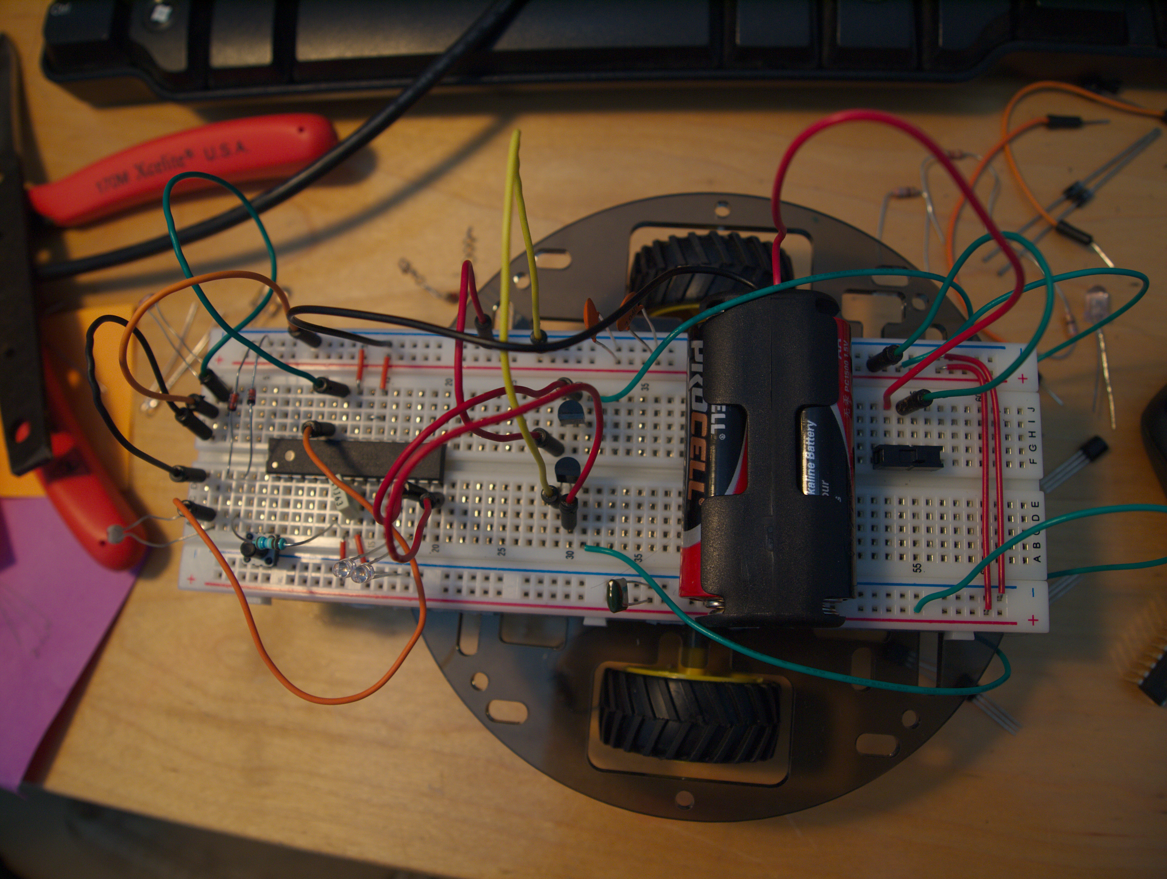
Top view of the ‘bot

What is a decoupling cap though?  Doesen’t the five dollar arduino already have them?

The answer to the second question is yes, but the cap was not big enough.  The problem the circuit was having was that the batteries were  trying to output a constant voltage.  This means that as current demands changed in the circuit, the battery had to adjust the output current.  With the microcontroller taking only a few miliamps, the circuit is not drawing much power.  BAM!  Motor turns on and what happens?  The battery needs to supply more current, but can’t.  Then the mcu shuts down as it looses power, sending a short pulse to the motor.  So bigger decoupling caps were needed to smooth out the power supply, which the caps do by charging up to 5V, and then discharging if the voltage drops due to sudden current demand.

So the symptoms were: mcu turning on and off, which I could tell because the status LED I had attached was flickering.

The prescribed cure was: Find all the capacitors on my floor, and stick them across the power rails.

Result:  REVOBot works!  Check it out here!  (In this video it is running away from light because I have the motors running in reverse).

Mini-Maker Faire @ Cambridge Science Festival!

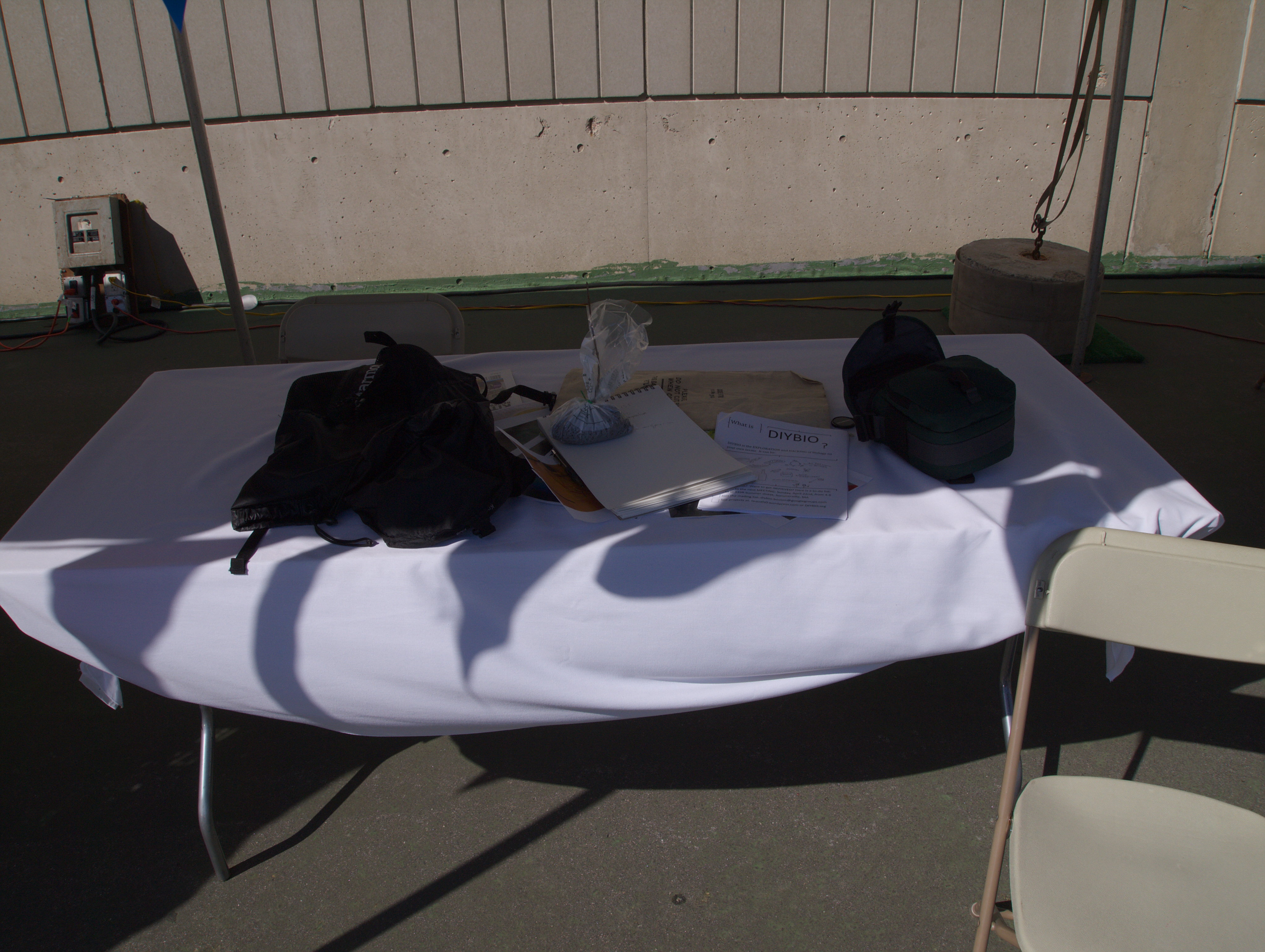
Really bad photo. I apologize…

I was at the mini-maker faire today representing DIYBIO Boston, and all I got was this really bad photo…

Just kidding!  I also talked to a bunch of AWESOME MAKERS and excited participants.  I even got to help Gui and Molly of Artisans Asylum lift a giant motorized barbers chair onto a truck, and see a bunch of <6 year olds run dyes from M&Ms in agarose gels.

If you are looking for my bio work because you met me at the festival, click here to see the things I have done with biology.

GFP Project: DNA Quantification

This is the nanodrop, a machine for quantifying DNA.

So now that we have grown up and extracted our plasmid DNA, the next question is how much do we have?  And how the heck do you measure the concentration and purity (amount of unwanted protein to amount of DNA) of nanograms of DNA dissolved in microliters of volume?

The answer is that we do these things with spectrometry magic.  It turns out that proteins (which are all made of amino acids) tend to absorb light at 280nm, while nucleic acids tend to absorb light at 260nm.  The concentration can be determined by the absorbence at 260nm (A260), and it turns out that “pure” nucleic acid samples have an A260/A280 absorbence ratio of 1.8 or higher.

This can be done with a spectrophotometer and nice quartz cuvettes, but this means you need enough liquid to fill the bottom of the cuvette, so you have to do a dilution.  This means more math to figure out the actual concentration, and it means that you have to do the figuring of the ratio and concentration by hand.  Fortunately, the lab at school recently got a nanodrop DNA quantification machine.  To use it you just drop 2uL between the silver jaws, and hit “measure”.

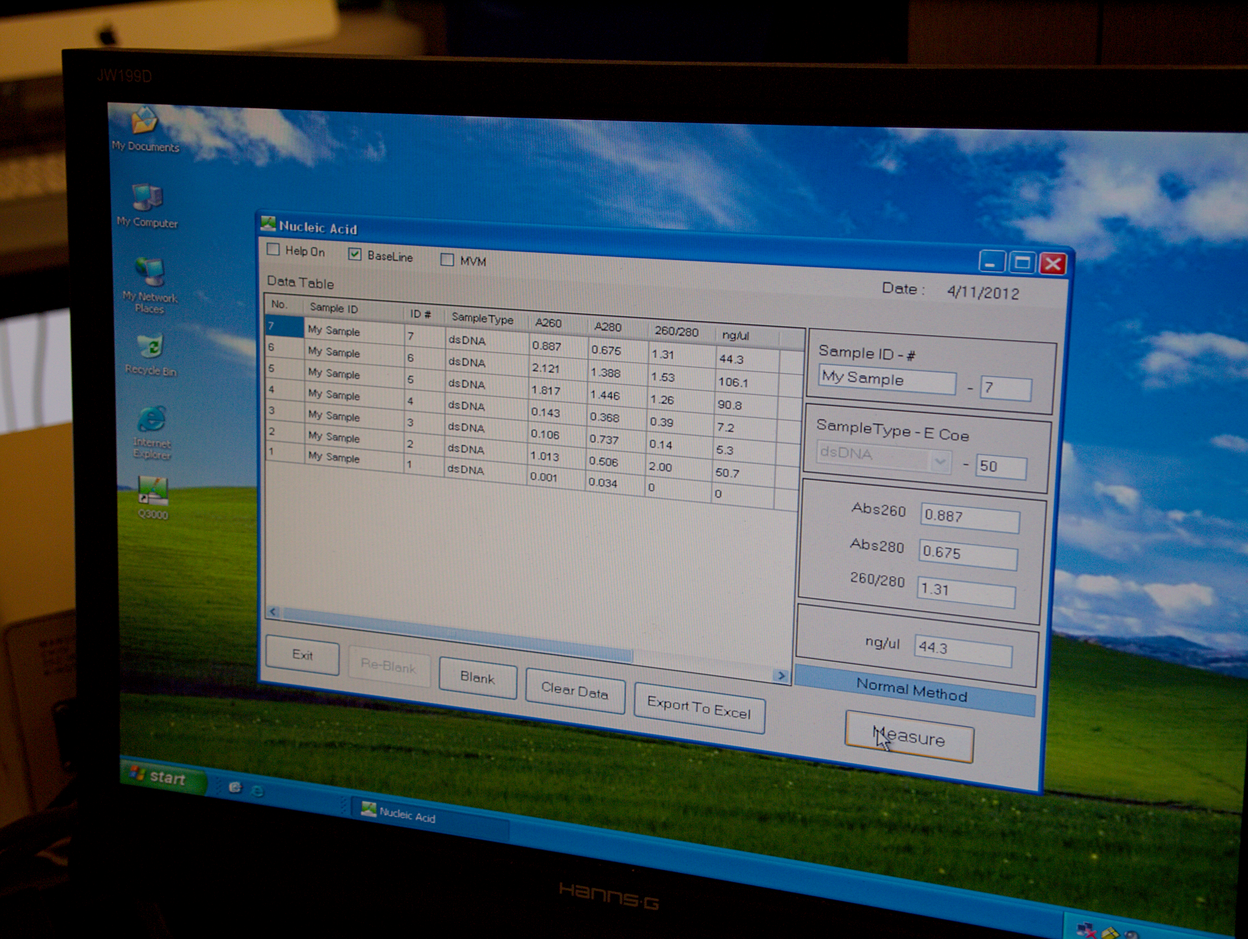
The interface for the nanodrop. The prep from BOSSLAB is at the top of the queue!

It turns out our prep went OK.  The stats are:

  • A260=.887
  • A280=.675
  • 260/280 1.31
  • concentration=44ng/ul

To give you an idea of how much DNA that is (and that is quite a bit of DNA!), the plasmid used for the initial transformation was at a concentration of 5ng/ul.  So this prep is almost 9x the concentration.  The volume of DNA from Carolina was 200uL; the volume of the prep we did was (if I recall correctly) 100uL (or more).  So we have now purified 4.5x  the amount of DNA we started with!  Pretty impressive.  The question is- now what do we do with it?

GFP Project Week Three: DNA!

Lets DIYBIO!

Well, the GFP Project has come full circle.  It started out about a month ago with the idea that a few people could get together and do some science together.  I would say that it has been a success.  In the past few weeks we have covered what I believe to be the “Hello World” of DIYBIO, which is to transform a plasmid into a bacteria, do something with the modified bacteria, and then get the plasmid back out.  Yesterday we closed the loop and extracted the plasmid.

Overnight Culture

The plasmid extraction went smoothly.  The Idea behind plasmid extraction is pretty simple, and it starts with an overnight culture.

Spun down cells

Then we centrifuge the tubes to pellet the cells.  This allows us to pour off the supernatant, as the cells will stick to the bottom of the eppendorfs.  The next step is to re-suspend the cells in “resuspension buffer”.

Resuspended Cells

Here are some resuspended cells!  Looking pretty good.  This is necessary so that the next few buffers can get to all the cells.

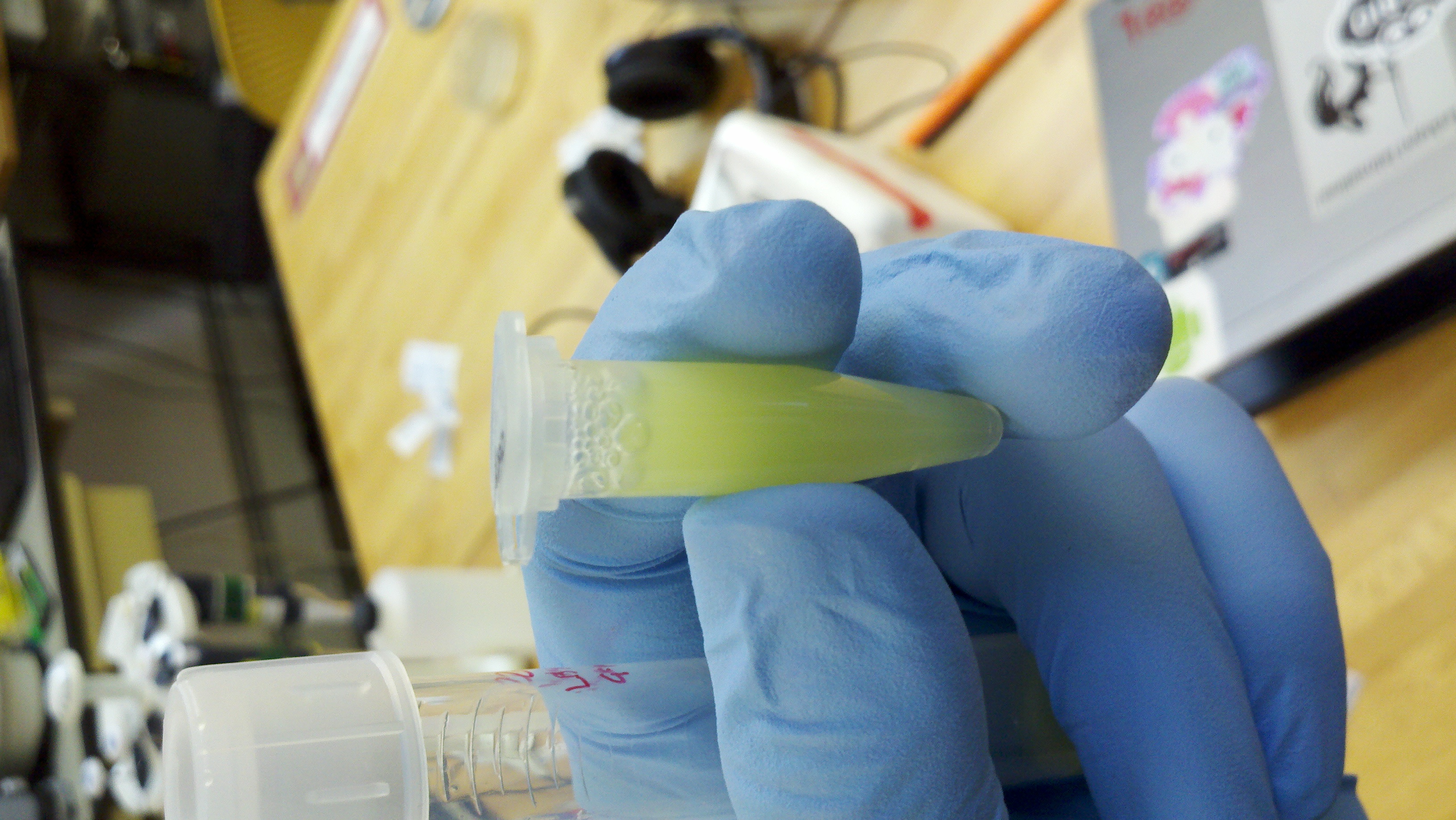
Lysed Cells

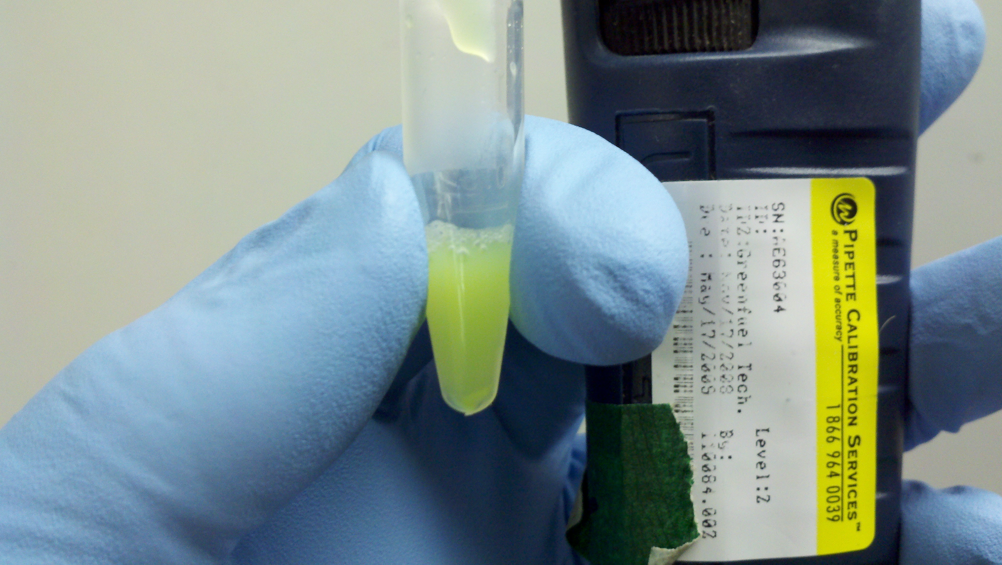
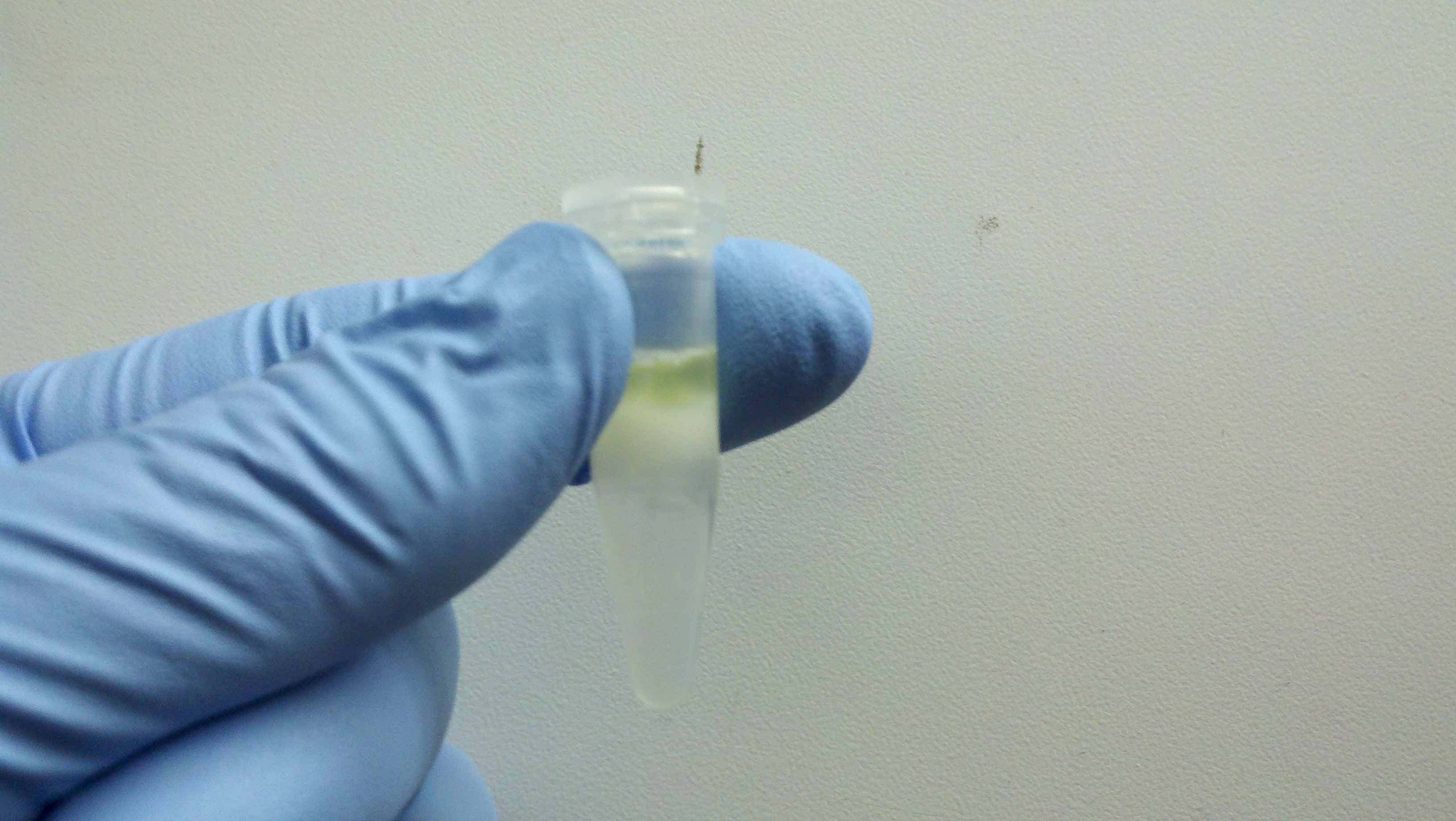
Here the cells are lysed.  As you can see, the lysis buffer seems to denature the GFP, as the tube is no longer very green.  The lysis allows the plasmid DNA to get out of the cell, and it also helps break down the genomic dna.  The plasmid DNA is a little tougher because of its circular shape.

Halted Lysis

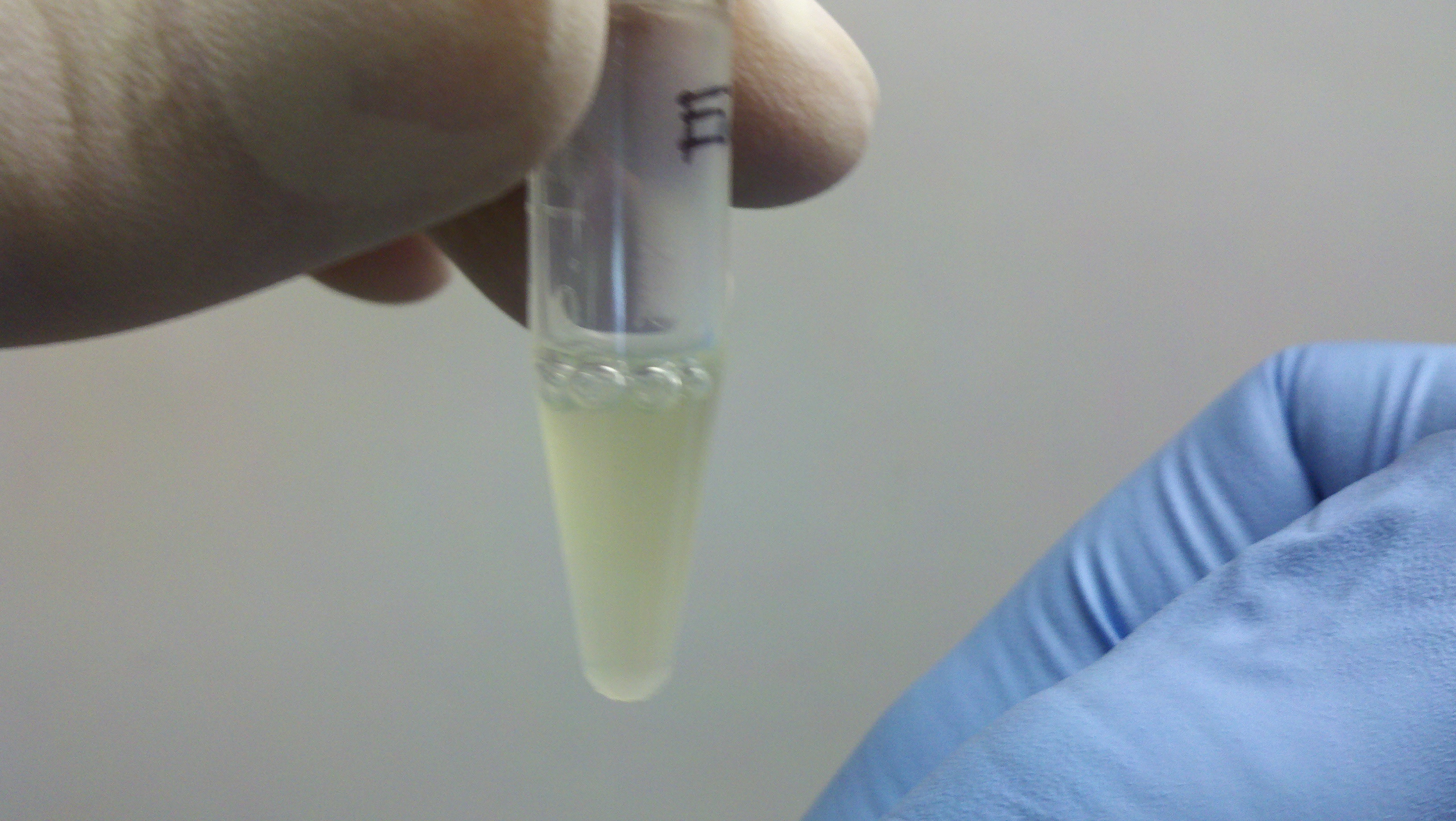
Now we halt the lysis, and this causes a change in the solubility (and probably pH and salinity), causing the extra cell ‘junk’ to fall out of solution.  As you can see, the GFP has returned!

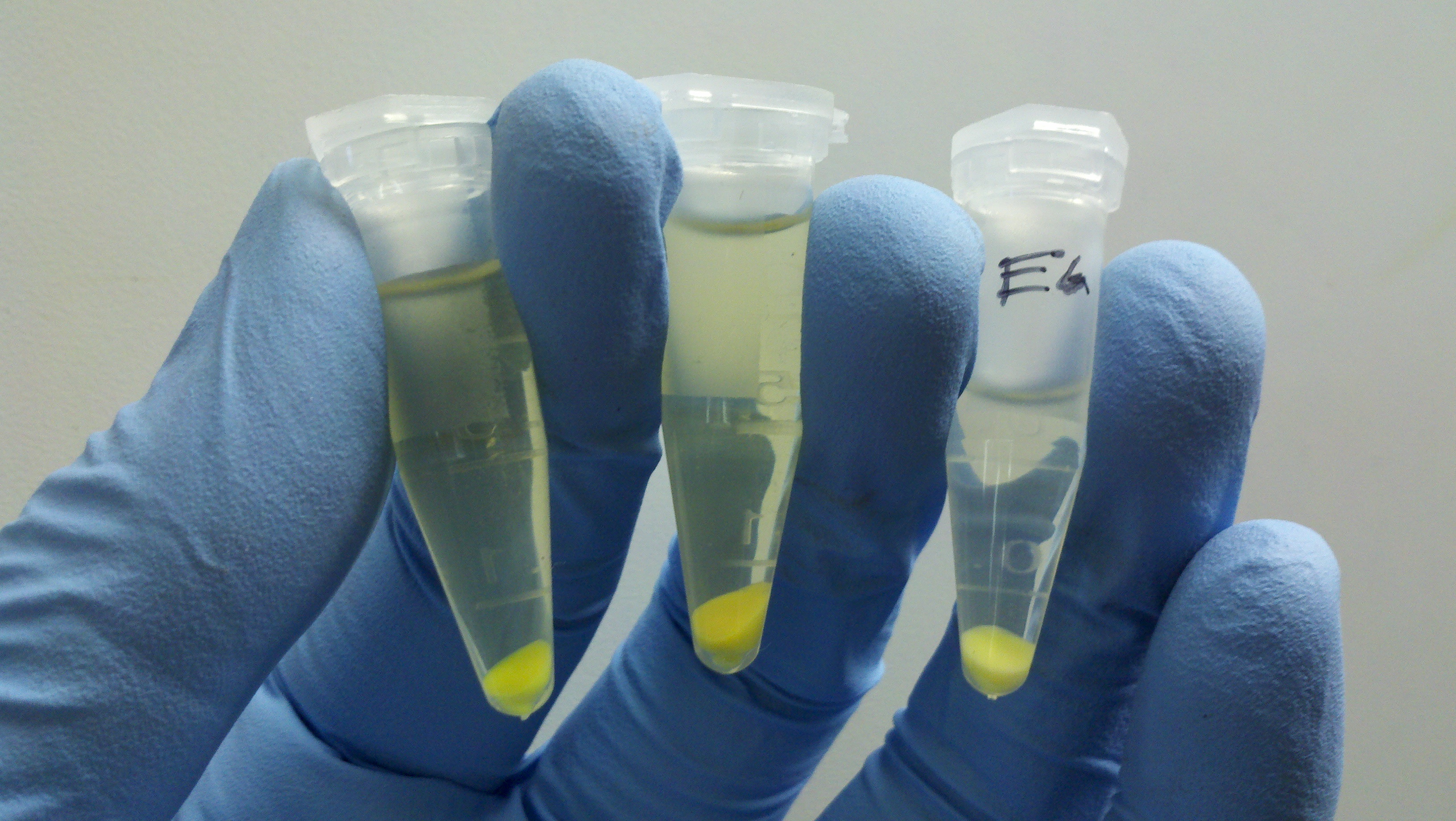
Pelleted Cell Debris

Now we pellet the cell debris in the centrifuge.  This should get rid of quite a bit of the cell debris, leaving us with the plasmid DNA and some other junk in solution.

Spin Column

The supernatant (liquid) in the tube with the pelleted cell lysate is applied to the top of the spin column, and then centrifuged so that the DNA is bound to the matrix (solid white stuff) in the column.  Whatever passes through is junk.  To remove some of the other cell bits stuck to the column, two “wash” buffers are applied to the top of the column and centrifuged through the column.  This removes other chemicals that have a negative charge like DNA, but that are not DNA.

Elution!

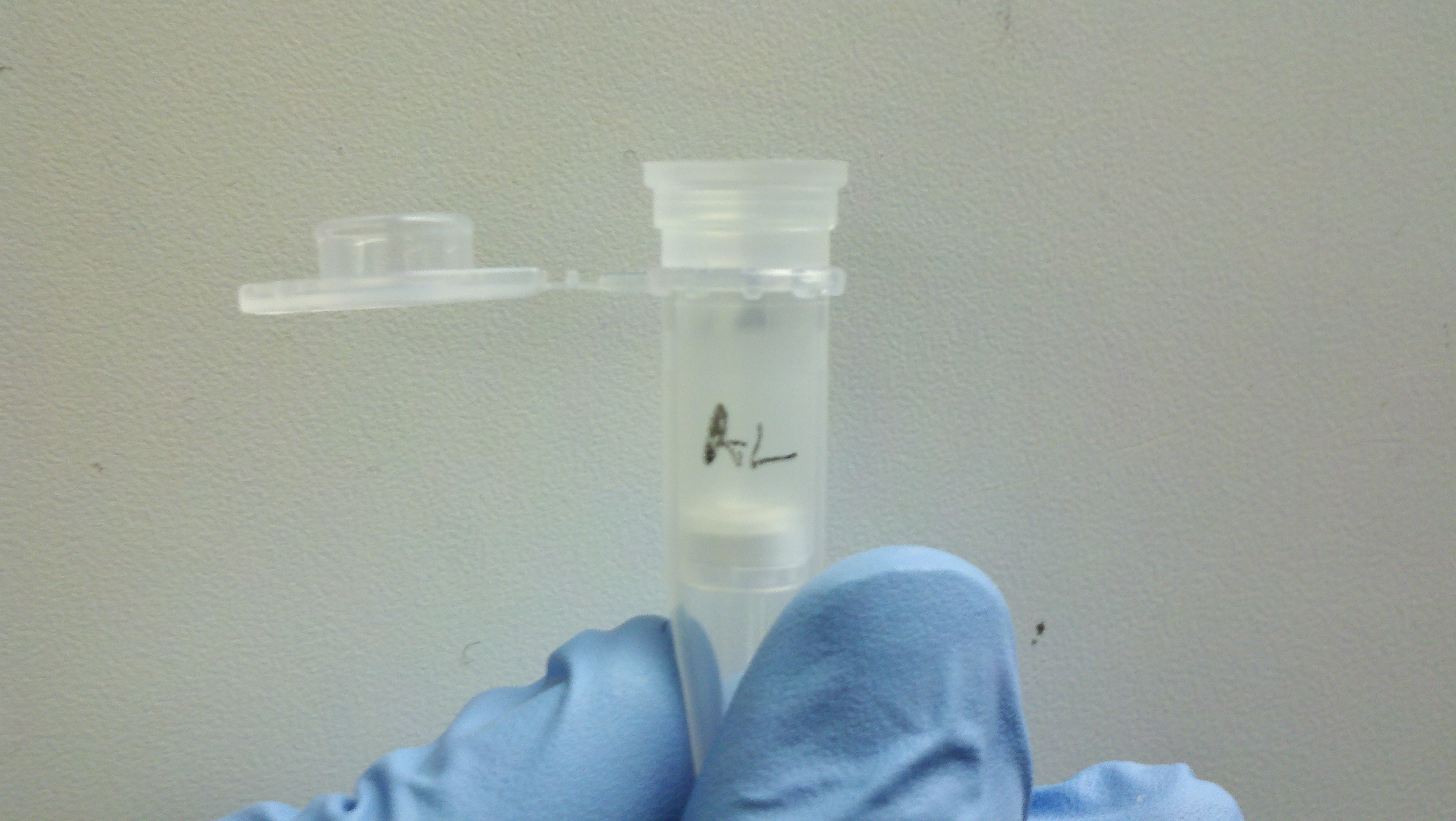
The final step is to elute the plasmid DNA from the column by applying (you guessed it) an elution buffer.  This washes the DNA out of the column.  In this picture, the spin column has been placed in a clean eppendorf that will hold the final purified plasmid DNA solution.

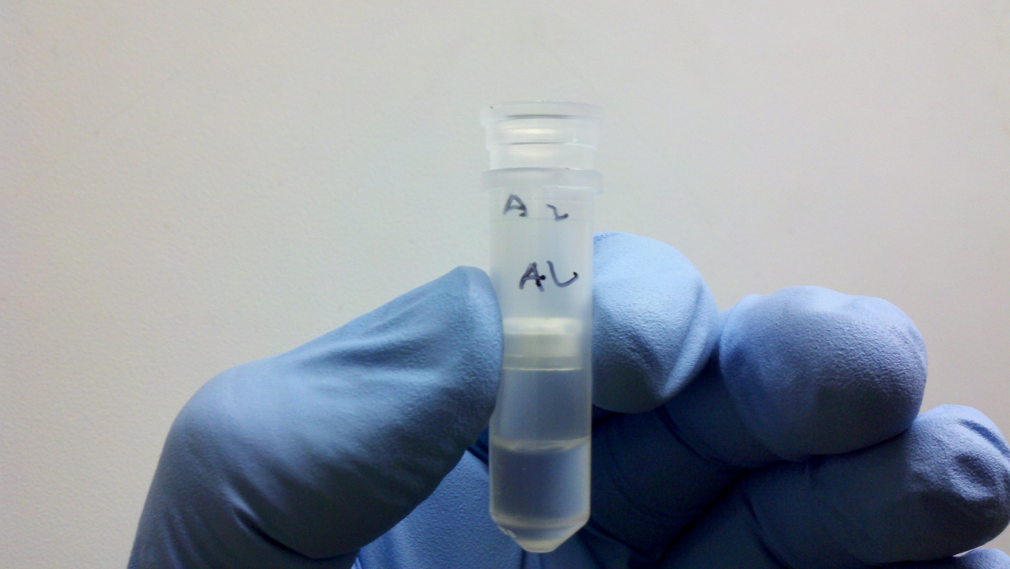
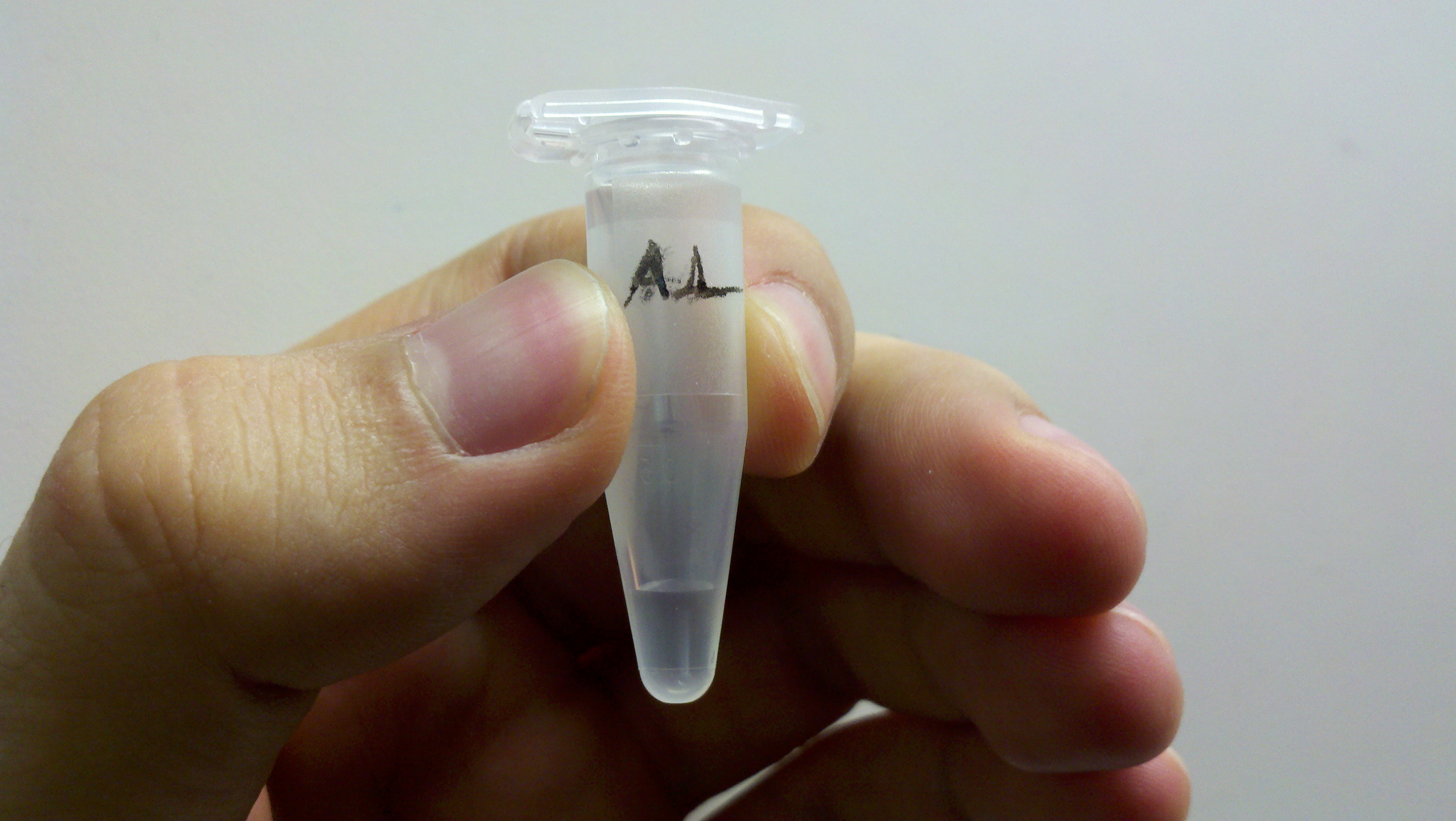
Purified plasmid DNA

Once centrifuged, you have purified plasmid DNA!