GKOS Keyboard Adventures

Recently I have become interested in chorded keyboards.  I see them as an incredibly under explored option in computer interfacing, particularly for engineers or people who are bringing a computer into a workshop/bench workflow.  To attempt to get used to chording, I installed a chorded keyboard on my android phone.  It is called the GKOS keyboard.

The first thing I noticed was how huge the keyboard was.  It took up roughly 70% of my screen, which is saying something, since I have a galaxy note ii.  This means that when typing, I can really only see a few lines of text, which can be annoying.  On the other hand, the keys are enormous! Instead of the tiny fingertip sized keys that normally adorn such keyboards, the large keys are roughly .5″ wide by .75″ tall!

Huuuuuggeee keys.

There is the keyboard.  As you can see, the “home” keys are very non-standard.  However, they are certainly the most used keys.  This makes it convenient and easy to type.  After a few days, I found that I was speeding up, although I was still lagging behind my querty-thumb-pecking speed.

The major downfall of this keyboard is actually the form factor of the modern phone.  While it is kind of fun to use, it is extremely uncomfortable on phones without a large bezel.  This is because the natural position of the thumb is somewhat relaxed, and the comfortable way to type would be to pivot your thumb around the base joint.

In portrait mode, the problem comes in that my thumb is a little longer than half the screen, and to hold the phone securely I have to have by hand across the back of it.  This means that in order to get my thumb on the keys, I have to curl my thumb up for the entire time.  This makes it very uncomfortable.  In landscape mode, it is slightly more comfortable, because it is easier to hold the phone, but still, the keys are right at the edge of the screen.

The other issue I had is that the keyboard is not one-handed, especially on my huge phone.  I want a one handed chording keyboard!

I enjoyed using it, but I have switched back to my querty.  The keys are now painfully small, and my pecking seems weird compared to the elegant chording on the GKOS, but I am faster and more comfortable while using it.
Indoxyl: An Incarnation of the USBTiny ISP

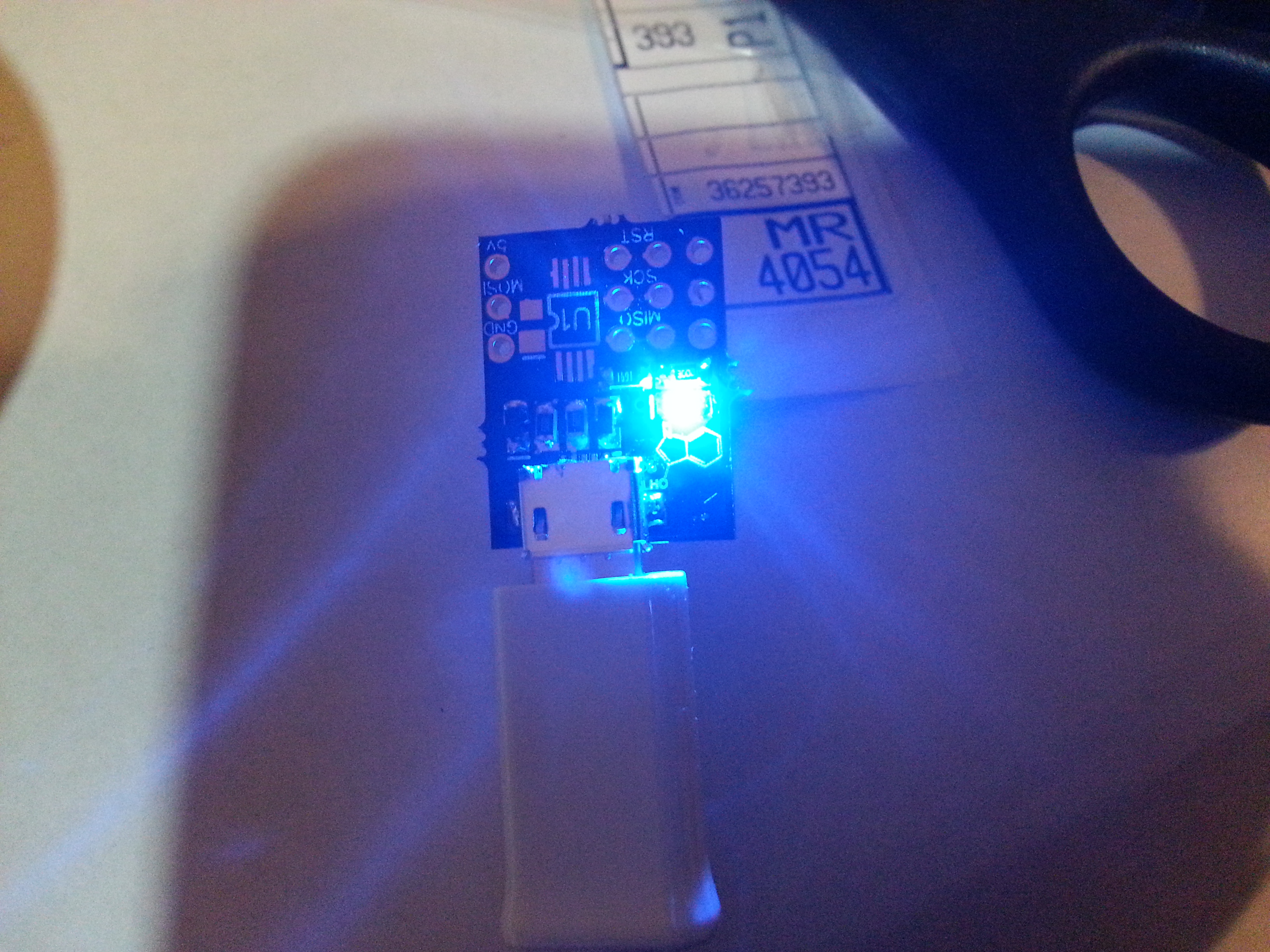
New Indoxyl Programmer

New Indoxyl Programmer!  The LED is a nice upgrade.

Indoxyl is the upgraded version of a board of the first board I made, a long time ago.  It is an AVR ISP programmer, and it is really handy to have these on hand to lend to people, or to use yourself instead of something bulky, like the original STK500 (which is my other option).  They are also incredibly cheap!  This devices BOM cost is under $5, including the board.  It is called Indoxyl because it is a precursor to a finished project, just like Indoxly is a precursor to Indigo.

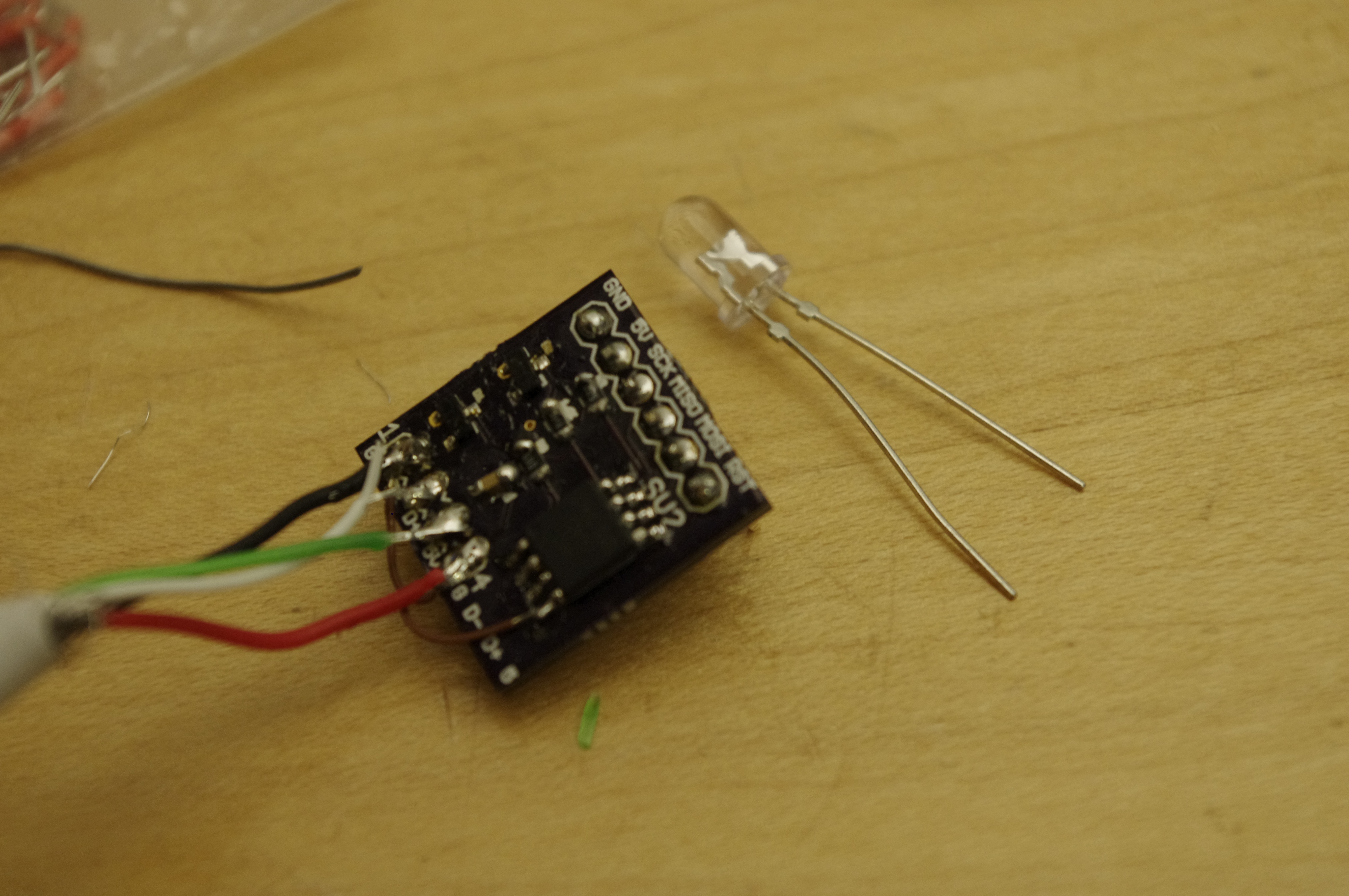
This board uses all SMD components and comes in just a bit under a half square inch.  It has both the standard ISP header (unlike the original board, seen below), and a breadboard-friendly header.

Design and Routing

The schematic was already very well known to me, but I added an “idiot lamp” to let me know the power was on.  I went with a blue LED because thats what I had on hand, and I like the color blue.  It was routed by hand in diptrace, which let me optimize the board fully.  In fact, has only two vias that are not for through-hole connectors.  I achieved this level of organization and routing by moving connections once the parts were in the board layout editor.  By doing this, I was able to reduce the complexity greatly, have less islands and reduce the need for vias.  This would not have been possible using autoplace or autoroute, because the autorouter cannot take into account the function of th board or the pins.

Documentation

Full design files are available here, on github (schematic, board, gerbers, assembly, and BOM).  This is the first time I got to use my galaxy note II to document something!  I was impressed with the ease of integrating it into my workflow.  The camera is fast, and produces reasonable images in  the relatively dim room that I was in.  Its nothing to write home about these days, but it is a big upgrade from my slow, but loved, droid X.  The really impressive thing is that you can write with the S-pen on the screen and record notes, embed media, and generally do whatever you want.  You can even export S-notes as PDFS!  It is pretty cool for fast, integrated documentation.

Old and jenk!  Notice the brown jumpy wire from the black wire to the chip.

Boston Hardware Startup Meetup #4

Boston Hardware Startup Meetup #4 at BOLT Accelerator was a blast.  Besides the copious amount of beer, wine, soft drinks and pizza, there were presentations from quite a few companies- the norm is three, but this month they squeezed in five!

There was a demo by Dash Robotics which is a company commercializing research on cardboard robots that came out of the bay area (Stanford/Berkley).  Their robots are pretty tough in terms of drop testing, and cheap enough that you don’t feel too bad if you step on them.  The kit is expected to be cheap, and bluetooth enabled.  I think these have a place in k-5 schools, especially now that kids have bluetooth enabled ipads and whatever.  Gotta start growing engineers while they are young!

The Peeko, from the Rest website

Rest Devices, from just down the street also appeared, and showed off their latest product, the http://www.restdevices.com/products/ (haha, like pico and peeaboo).  It is a onesie that harnesses the technology from their sleep shirt, which the company pivoted away from since it was a diagnostic device and required FDA approval.  The technology is some kind of iron on conductor.  They claim they can measure respiration, skin temperature, activity and body position with the sensors in it.  My guess is that the iron on conductor acts as a strain gauge or force-sensitive resistor to figure out respiration, and maybe body temperature with a PTC resistor (aka thermistor) or thermocouple made of two dissimilar materials laminated on each other.  Anyways, this onesie is networked seven ways to Sunday, and comes with an app that displays the information about your baby.  They will also be collecting data from your baby and doing things with it.  Who knows- maybe there will be a diaper change predictor or something.

Weartrons showed off the development of some kind of running or jogging device for those that cannot tear themselves from their tablets.  It synchs up the bobbing of your head/body with the text on your tablet.  It’s an unusual concept, but after trying to read or watch videos while on the treadmill, I can certainly see how it could be useful.  I would give them a picture here too, but they all of their pictures are of the product in use, and it would be so small in my layout that it would be hard to see!

Infinite Corridor Technology showed off their limberboard, which is basically an arduino (although they don’t call it that) clone on a flexible PCB.  I have seen this before, and I was underwhelmed by how the limberboard is priced and differentiated from other wearable electronics.  The only advantage it has over the seeeduino film is that it has patent pending zig-zags (which are quite clever) that allow some sections to stretch without putting any stress on the components.

The limberboard is clearly aimed at makers, but if they get their patent, what happens when you buy one?  Are you granted a license to the technology?  Can then use their flex connectors on your pcbs, or does the rest of your circuit have to be non-strechy?  A lot of IP questions come to mind, and as someone who makes things, that turns me off.  The board also seems to lack any way to mount it to anything or connect any parts to it, unlike the SEEED film.  Their crowdfunding campaign begins in a week, and it is priced at ~$60 instead of ~$10 for the film.  Maybe that campaign will provide some answers.

Onehundred has a particularly tricky name to get search results from, so they also are imageless.  They are employing a backwards, do-it-for-the-lulz approach to manufacturing.  Instead of designing something and seeking somewhere to build it, they are going out to local machine shops and manufacturing facilities and asking what can we make here.  It is a bizarre concept, but I think it is really cool.  They demoed some bottle opener/multitools that they had had machined locally.

Atmega32u4 Breakout

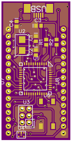
Frustrated by a lack of stock of adafruits breakout boards for the atmega32u4, I decided to design my own.  Yes, I could buy a teensy, but a teensy has (what I consider) a design flaw in that it has pins on the end which cannot be breadboarded.  The arduino leonardo is overpriced and a pain to connect to a breadboard.

Features:

  • Atmega32u4 with all non power or ground pins broken out to header pins on edges of board
  • 3.3V regulator on board broken out to header pins, for powering 3.3V devices
  • The easiest-to-solder SMD USB mini B connector I could find
  • NX5032GA-16.000000MHZ crystal for full speed USB development.  Woah, thats a lot of 0s
  • Broken out Atmel ISP header
  • Button to reset chip for bootloader

And of course, it is breadboardable and fabbed by the fabulous OSH Park, on sweet purple and gold boards (.063″ thick). The final thing to do is to throw the silkscreen layer on there, so you know what pin is what!  All the files for this board can be found in the downloads section, including a BOM ($13 at qty 25) and gerbers.

The Morini Roars!

Another day working on the ‘ped

Finally got the M02 running*!

video: click here

*After week of being solidly confused by the symptoms, and unable to get a clean plug chop (because it wouldn’t run for long enough), I found out why I had no power.  The symptoms were:

  • no power
  • no idle
  • revs up to high rpms, occasionally dies
  • after it ran, it would be hard to start

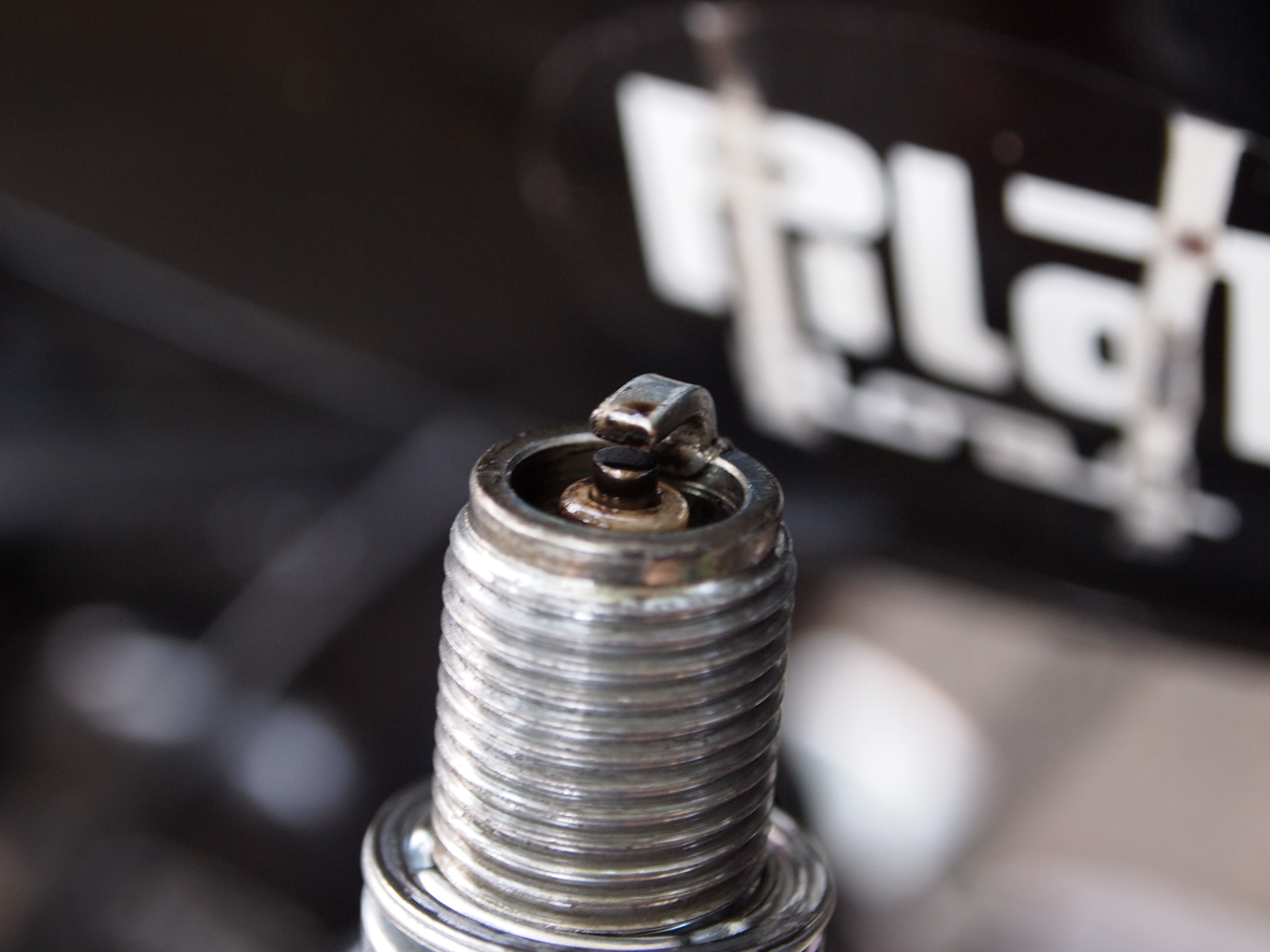
It looked like I was running rich when I checked my plugs, but it was hard to tell, since I have never seen a working moped plug, and its hard to tell from the pictures online what was is good and what was bad.  I thought that it might have been oil-fouled, and the waiting after the engine ran let the oil drip off the plug- it turns out, I was wrong.

Oil fouling?

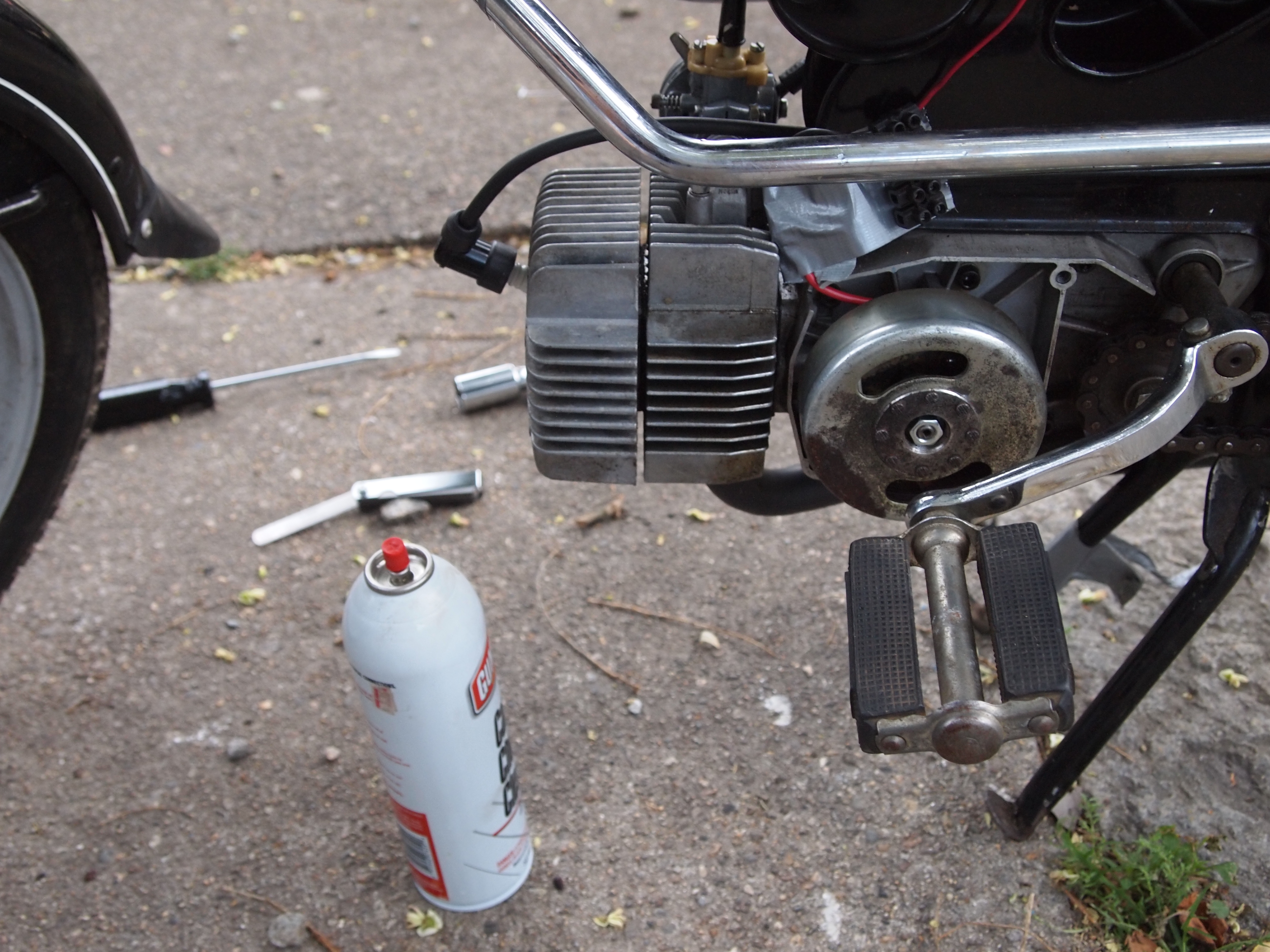
The symptoms I described are actually being caused by a vacuum leak.  I think that the cool down was needed so that the metal would shrink and re-seal.  Based on a spraydown with carb cleaner, the leak is between the head and cylinder- so I need to either make or fab a new head gasket.  I have a new stock aluminum gasket on the way, as well as gasket paper…we will see which one gets here first.  When it eventually arrives, it will be time to take the head off the cylinder, maybe sand down the mating surfaces, and then put in the new gasket.

Ghetto Cruise Control (caps lock for my throttle)

The good news for this update is that I also went to harbor freight and picked up some swanky shop towels ($6 for 25!), and most importantly, a set of feeler gauges for setting the timing.  So far I have been using a piece of aluminum flashing that is about .03-.045 mm thick depending on the day, and after adjusting the points with the gauges, it started right up!  I can even start it with one hand, if i work the clutch with the other hand and tie the throttle up with one of those handy new towels.  Which I had to do to get it running for the vacuum test.

Morini Ignition Magneto Rebuild

After installing my new spark plugs and pipe, I discovered that I was no longer getting a spark, probably due to some creative tweaking of the starter coil.  Oops.  So I decided that I might as well replace my points and condenser while it was all taken apart.  This should be useful to anyone rebuilding an M01 or M02 ignition- as far as I know there is not a clear guide on how to do this elsewhere.  It may also be useful if you have another moped, especially so if you have a Dansi ignition.

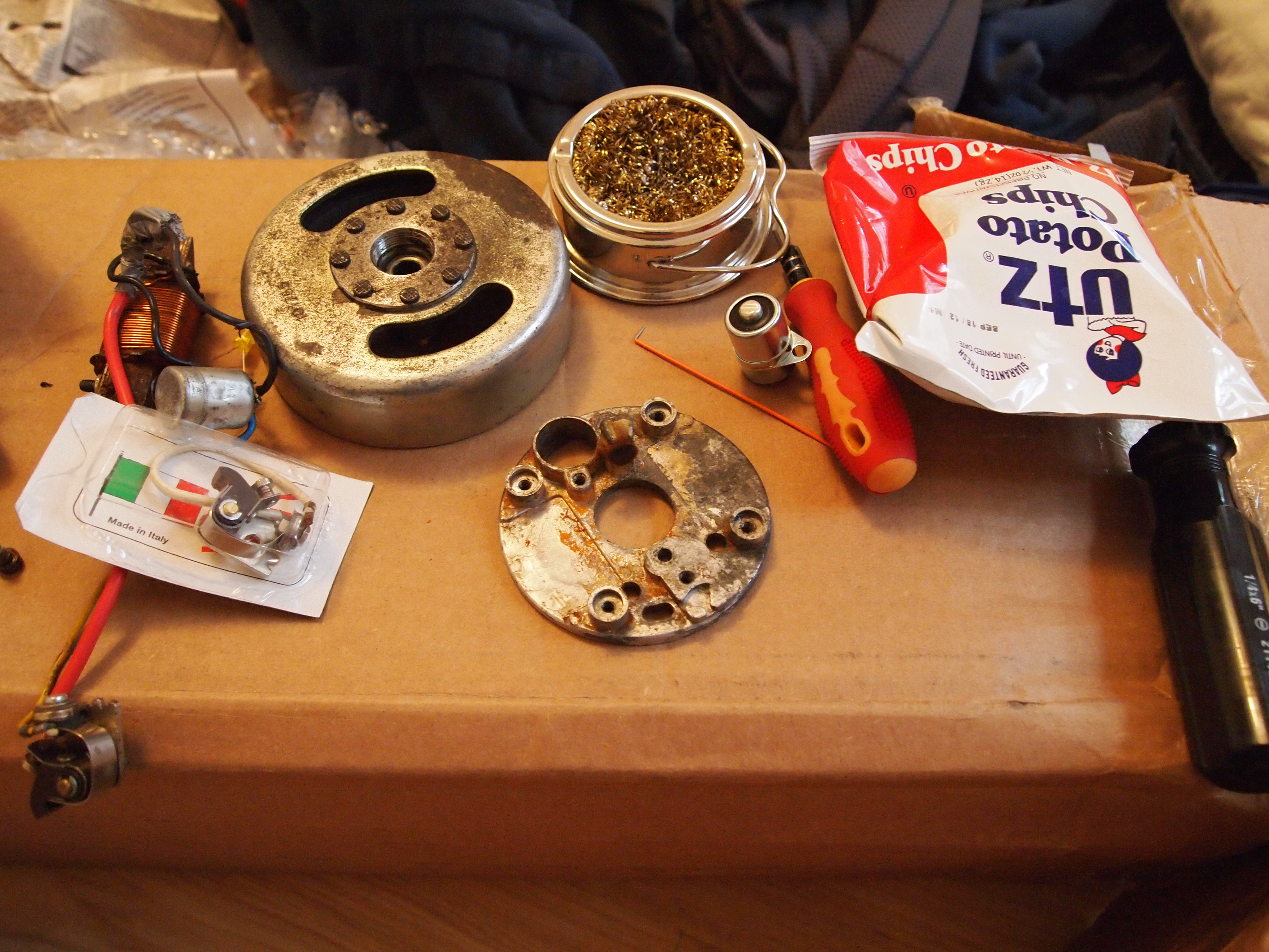
Get all your parts together on your workbench/cardboard box. Don’t forget snacks!

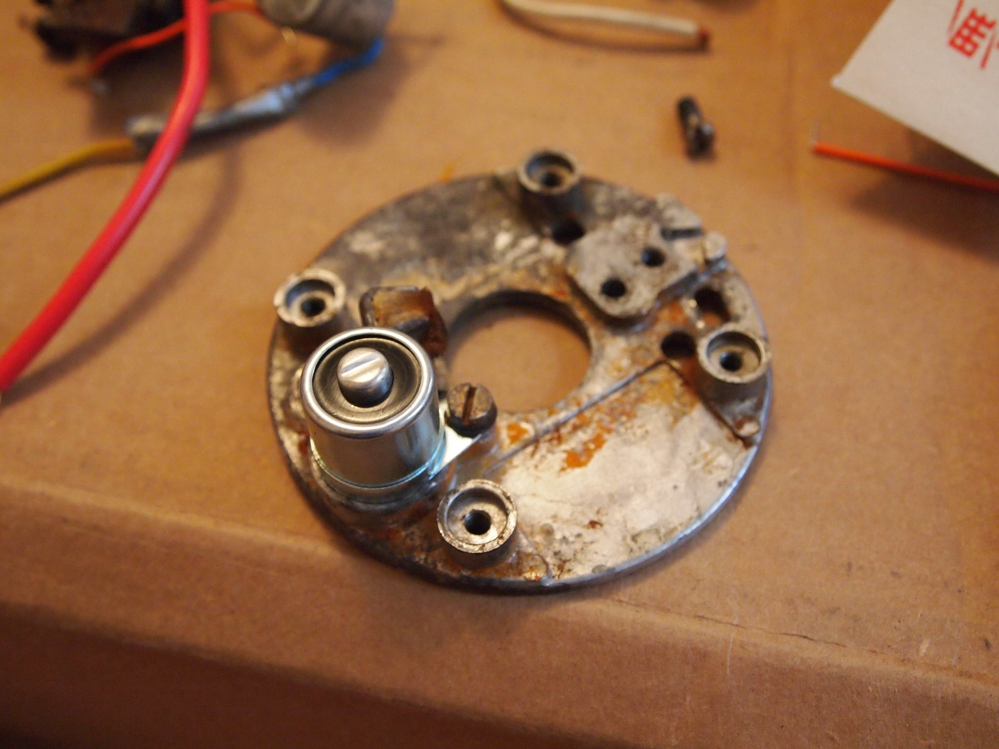
As you can see, the first step is to acquire a large cardboard box (or if you are lucky and have a table, use that), and put all your parts on it.  The part in the center is the stator plate, which is what the points (in the box with the Italian flag) and the condenser (round thing next to the screw driver) bolt on to.

The condenser should slide right into the stator plate. Mine was an 18 mm wide X 25 mm tall condenser

The first thing to do is to bolt the condenser onto the stator plate.  Not all stators use bolts, some are held in by friction- but this one has a convenient hole that you can bolt down.  The important part is that there is a good connection from the outside of the condenser to chassis ground (which is easy, considering how big the outside of the condenser is).

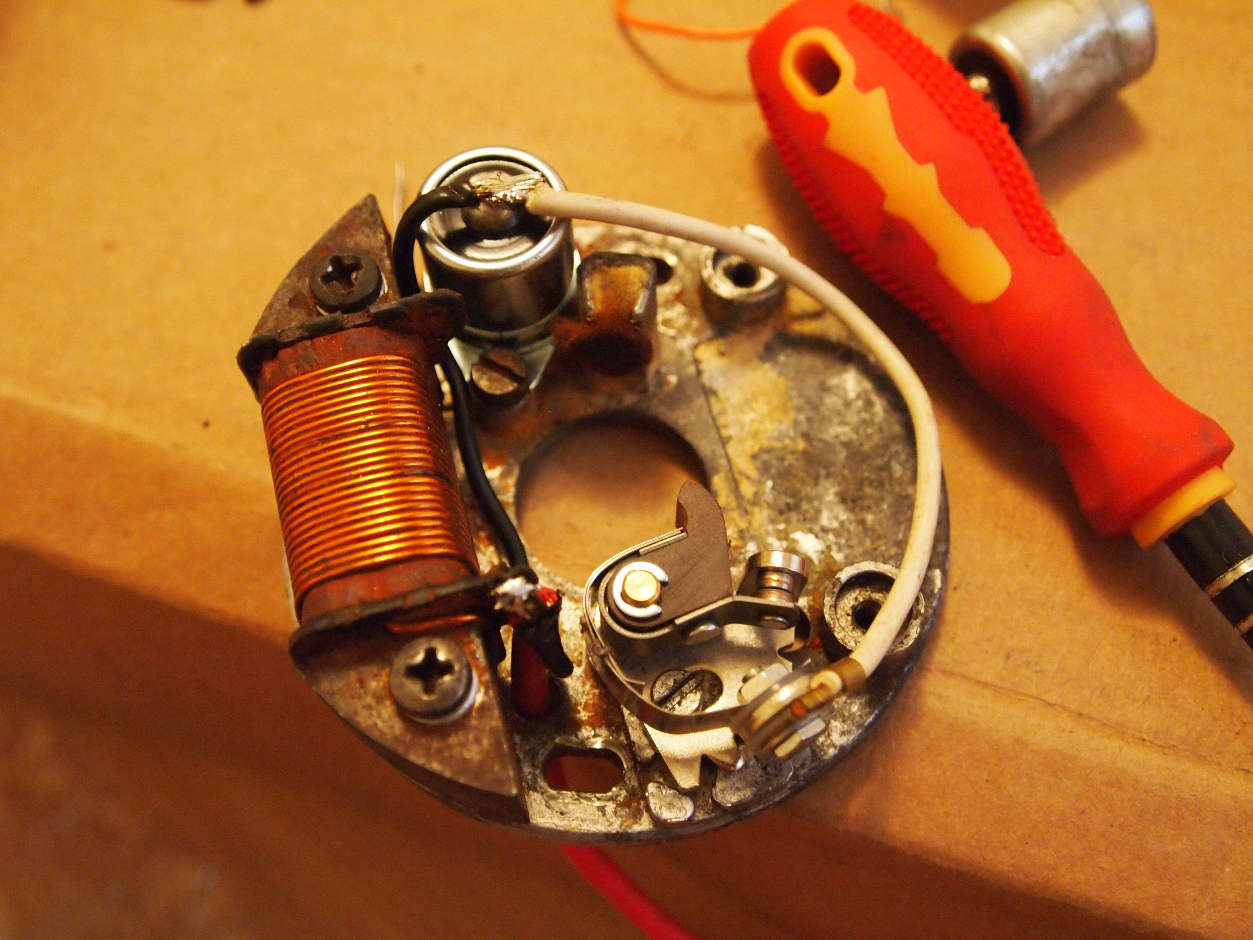
Here it is, all soldered up.

I skipped a few steps here, but the next thing to do is to screw the points in and attach the coil.  The points have a post that comes out of the bottom, that goes into a hole in the stator plate, and a slot for a screw.  The slot is very important because it allows you to adjust your point gap by changing where and how much the rubbing block engages the flywheel.  The coil is attached by two bolts, and should have only one end that comes out of it (the other goes to chassis ground).  The end that comes out of the coil should be soldered to a wire going to the condenser, and to a wire going to the high tension coil that feeds the spark plug.  Make sure to route all your wires AWAY from the outside of the plate!  Getting your wires chewed up by the flywheel is not cool.  In fact, it is so not cool that the engineers put a little hole in the stator plate, just so your wires can avoid the flywheel.  Clever.

Here it is on the bike. The red wire goes to the ignition.

Here it is on the bike!  The red wire goes through a little hole in the left hand side engine cover, and the flywheel is attached to the crankshaft by the woodruff key.

Now you may be wondering…did it work?  That is still to e determined, because the woodruff key needs to be “adjusted” with a file.

Woodruff Key Removal And Replacement

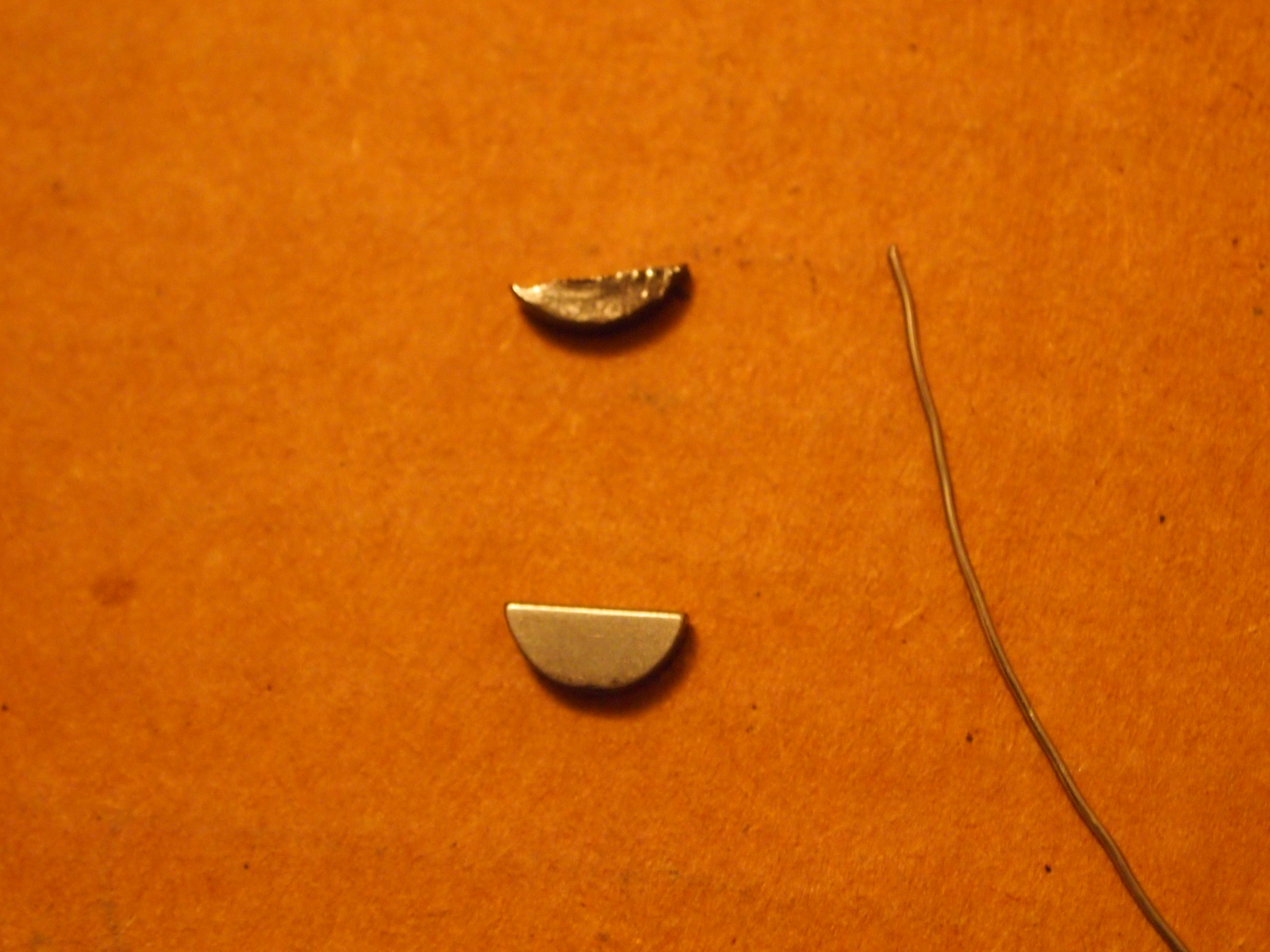
old key, new key!

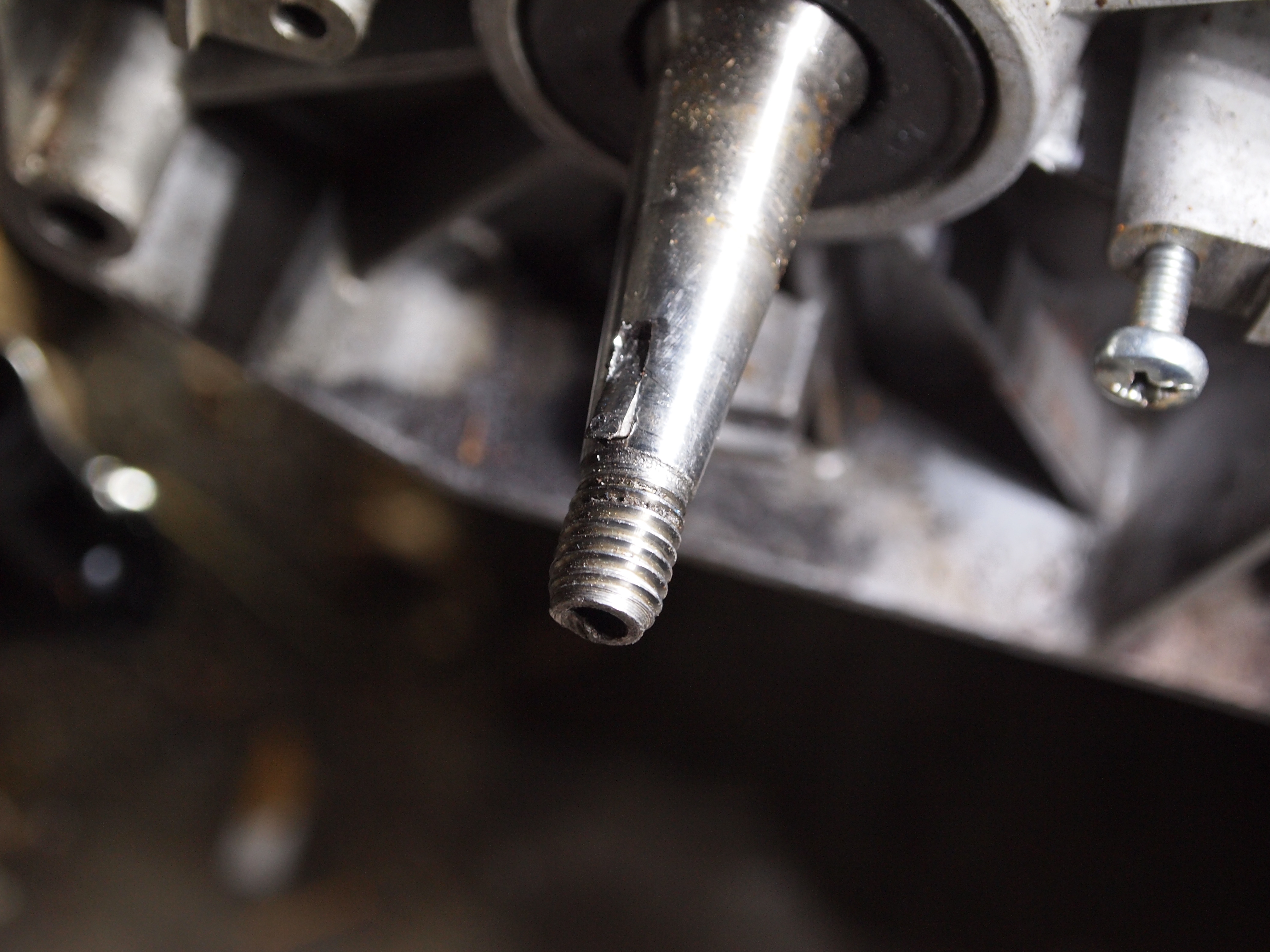
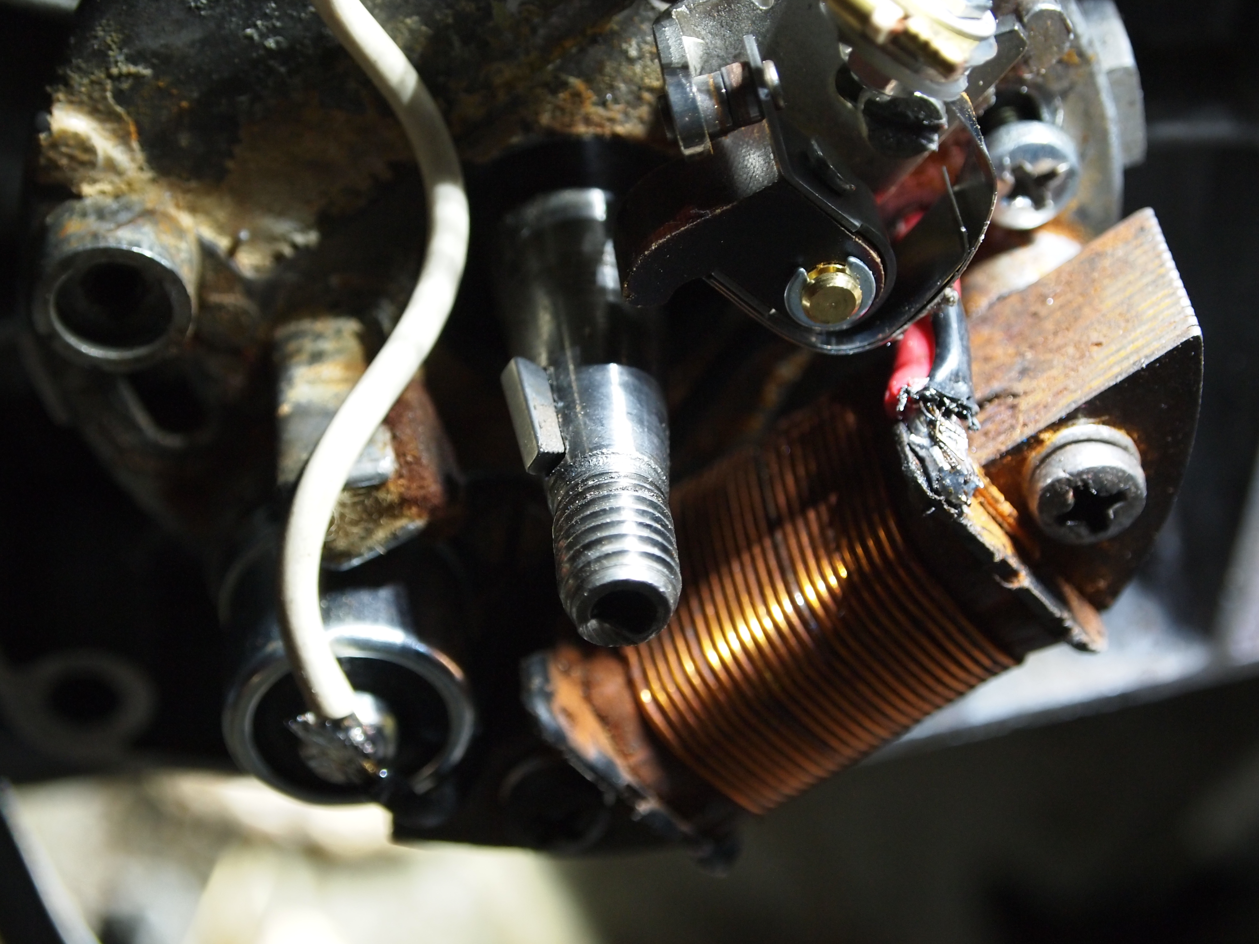
A woodruff key is a semi-circular key that is very irritating to remove if it s sheared off, because the slot cut for it is round- you cant just push or pull the key out like you would with a square keyway.  Shearing, of course, something that would happen to a 50 year old moped.  I started noticing wear on the key, and in a flash it was totally gone!  Completely sheared off to the level of the crankshaft, where it is supposed to engage the flywheel to create sparks/power lights.  So of course the solution was to order a new one from treats, who shipped really fast (and is not the company who took forever to ship).

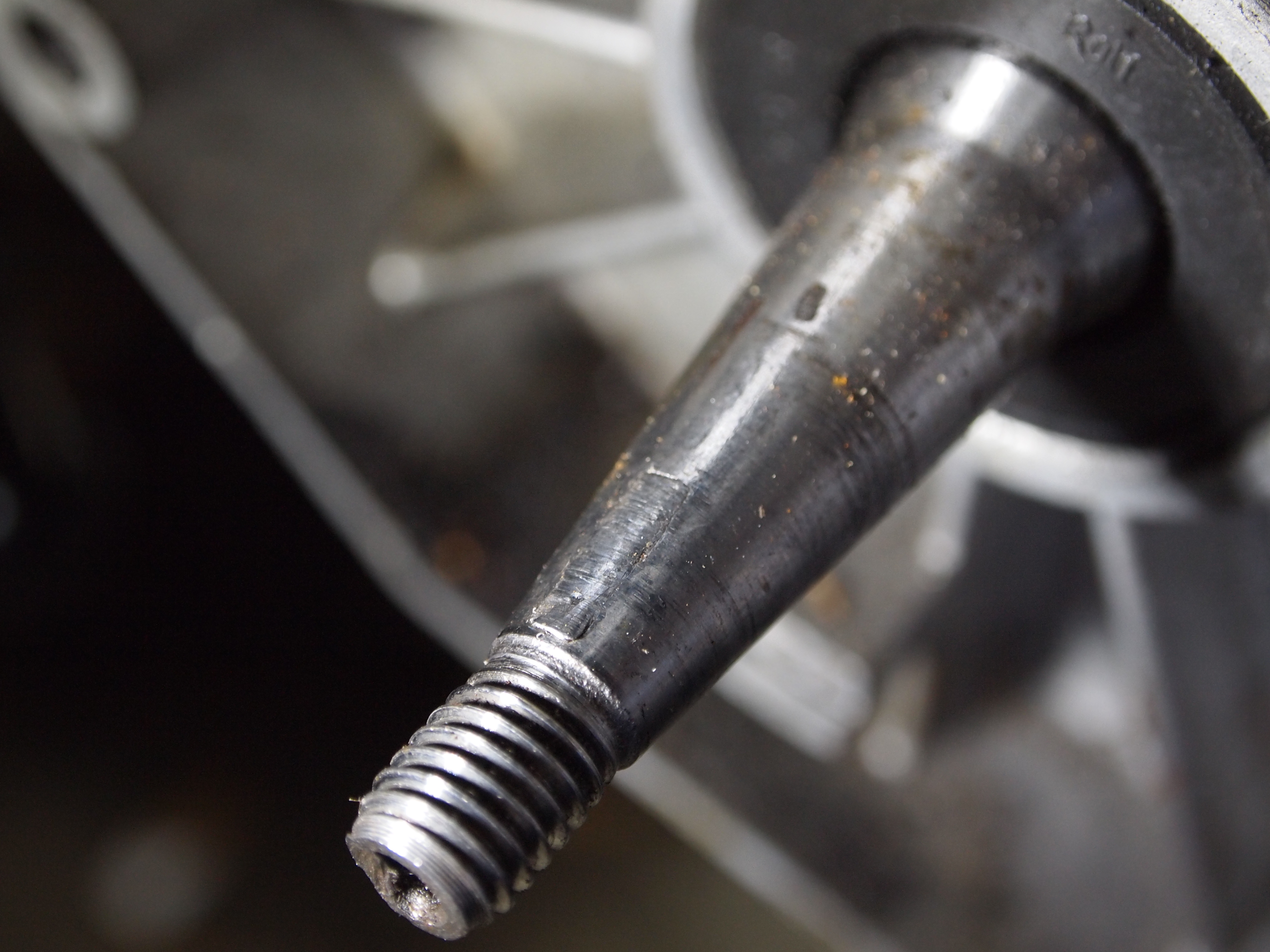
If you look closely, you can see the key that is totally sheared off in the shaft.

Once the key was in my hot little hands,  I was stuck with the task of removing the old key.  This was a daunting task- I don’t know how much abuse the bearings on the crankshaft can take, and the solution to stuck/sheared keys involves a hammer, a punch, and a steady hand.  The trick is to smack one side of the key and use it as a fulcrum to get the semicircle to rotate in its seat.  Once one side is sticking out, the key can be further loosened by smacking it so that it rotates back and forth, until it can be grasped by pliers or vice grips and yanked out.  Unfortunately, the key tends to be small- mine was 2.4 mm across, which meant that beefy punches were out of the question.  You definitely want something beefy like a center punch for this, because a pin punch of such a small diameter will bend.

After some judicious smacking, the key came loose

Once mine got a little looser, I  managed to grip it with pliers and pull it out.  It was surprisingly not that hard.  The last step was to install the new key in the slot.  True to form (for this project) it was a little small in the width department, and a little tall in the height department, so some loctite and filing may be in order.  Despite that, the new key is pretty good as far as rotating the piston/chain/magneto so I am optimistic that this will solve my no-spark issues.

Happily installed in the flywheel.

More Morini Repairs.

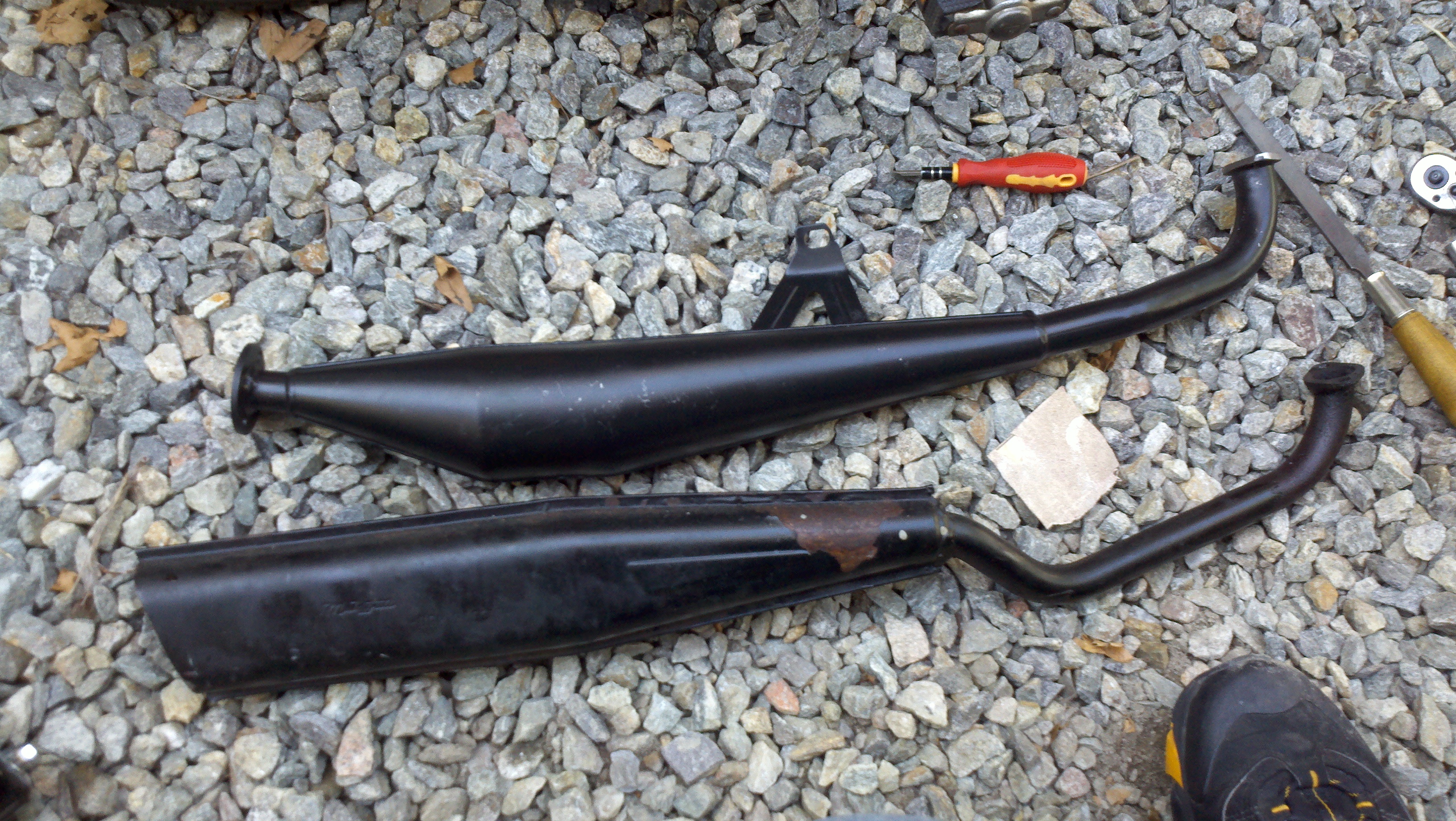
Old pipe has a nice bend so i have more clearance, new pipe is not full of carbon. Maybe the old one will make a comeback someday.

Since I knew the old pipe on my morini M02 was clogged, and also restricted, and since there was a large moped parts sale, I decided it would be a good idea to pick up a new one.  I took advantage of the sale to also pick up some carb parts.  My carb wasn’t really “broke”…but was certainly leaking.  This was no fault of the 50-year old dellorto (sha 14-12, for those who are curious), but the gas line that I installed turned out to be a smidge too big to really clamp down on the fuel banjo, not to mention that the in-line filter behind the banjo was probably clogged as well.

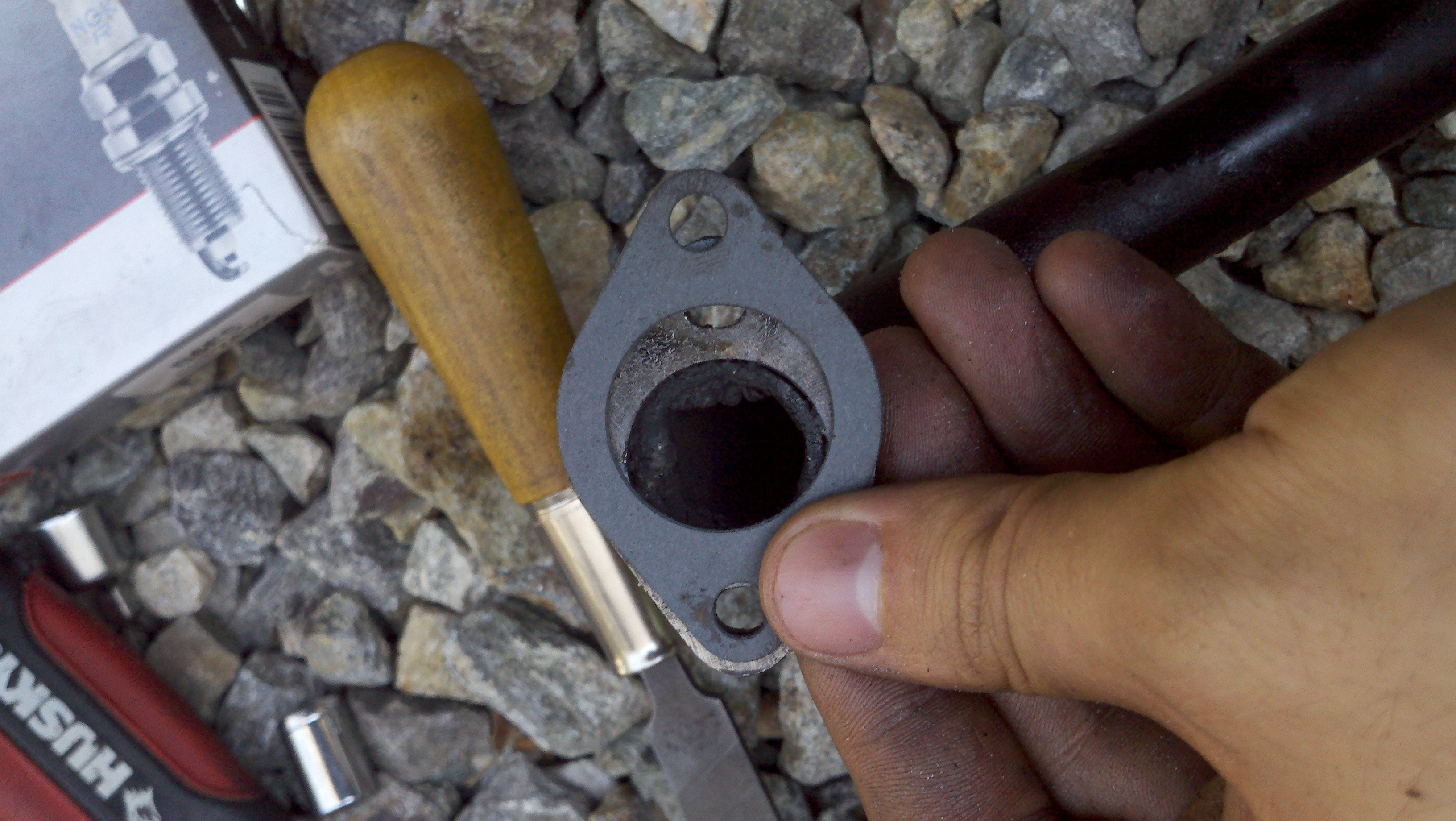
As you can see, the new gasket doesn’t fit the old exhaust header. Or the new header, for that matter. The holes are too far apart.

So, after some shipping snafus on the part of the supplier, my parts arrived about three weeks after I ordered them.  Grr.  And, true to this being a project bike, they didn’t fit!

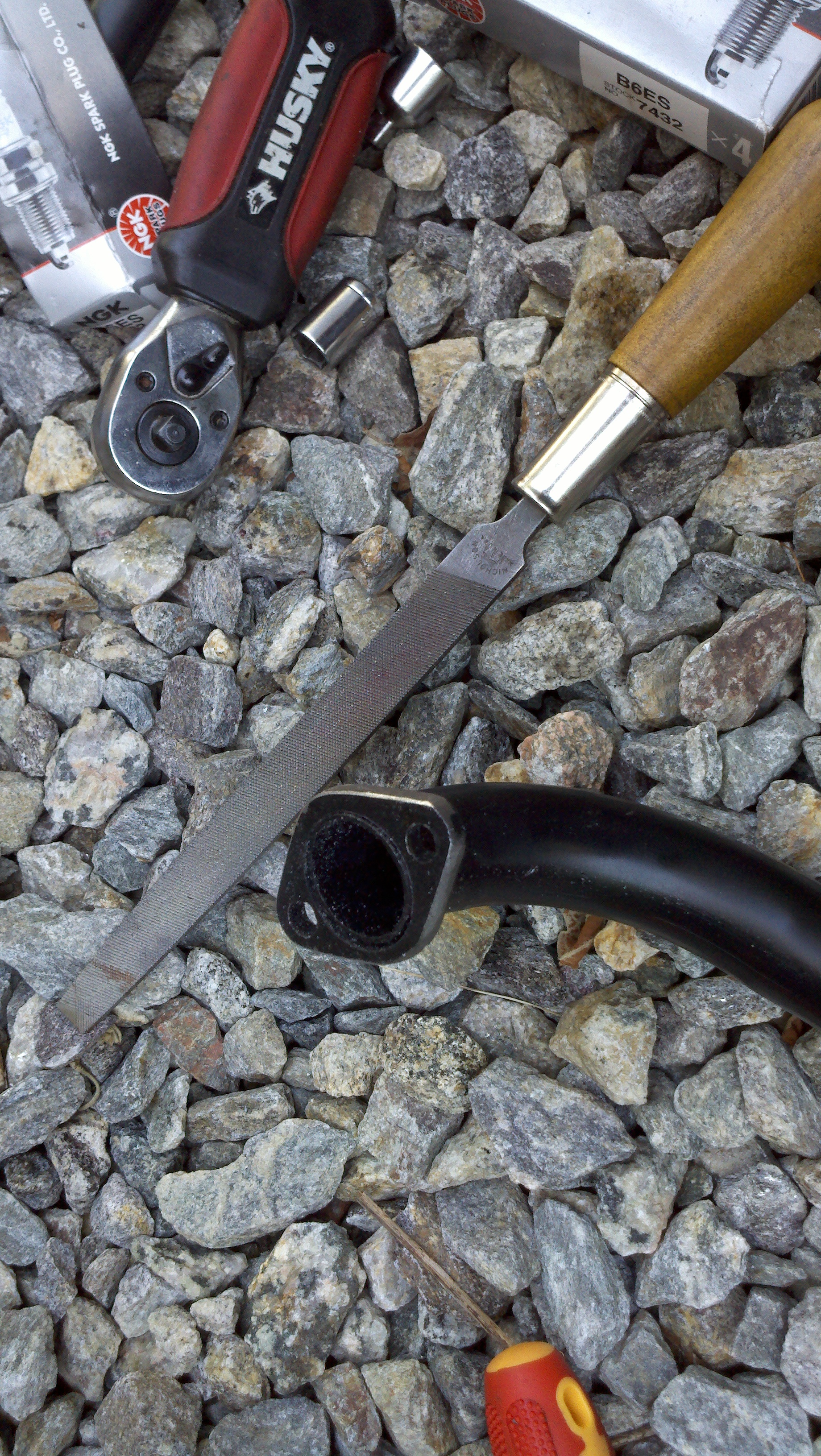
Thank goodness for tools. I had to take about .5 cm off the whole outside of the exhaust header.

The exhaust header, for the metrakit MKIII exhaust was waaay too big.  I think the cooling fins on the engine block might taper, so it is possible they just took a bad measurement and produced a bunch of exhausts that don’t fit.  I guess I will just have to expect a lot of filing and fitting in the future.

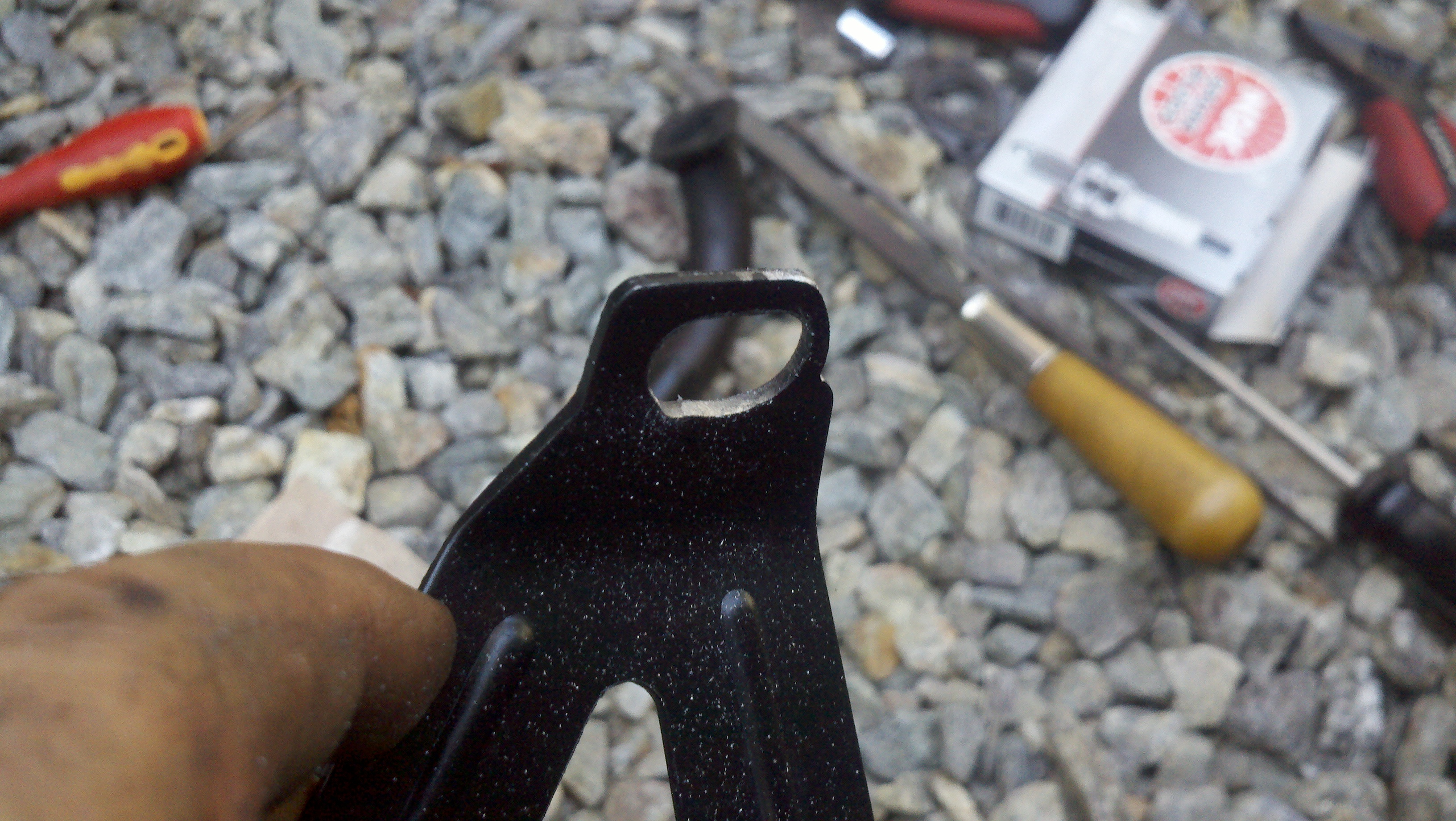
The mounting bracket needed to be enlarged. Lots of filing was required to do this.

After a lot of filing, I managed to get the exhaust to hang onto the bolt that used to have the center stand spring attached to it.  I don’t know what the final solution to the problem will be, but it may end up being some kind of hack-and-weld job that attaches the new expansion chamber to a better-angled pipe.

I also picked up some B6ES plugs from the un-named supplier, because of some advice I got from moped army, where someone pointed out that I had the wrong plugs.  oops!

Good thing someone caught that.  ES stands for “Extended”, and the extended plug is in fact, quite a bit longer than the regular plug.  In a 50 CC engine, this is kind of a big deal!  My estimate is that they were maybe 3CC larger.  If you take the original compression ratio of 7.5:1, that means that the compression with the HS plugs was roughly 6:1- which would dramatically decrease power.

GelGreen: As Good As Advertised

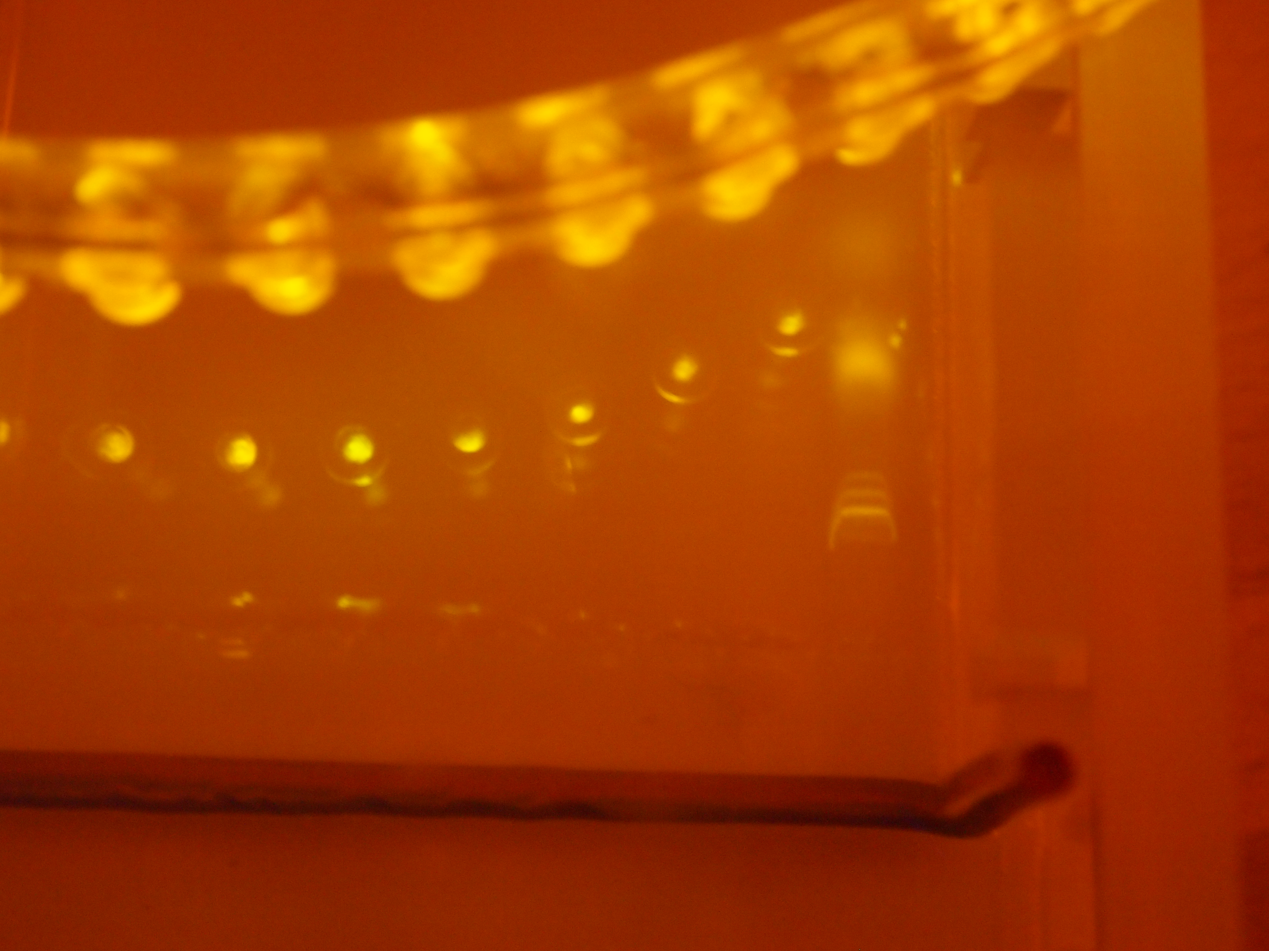
Check out the bands on the right! Its a DNA ladder. Its pretty smiley because I was running at high amperage just to test the new stain.

I ordered some GelGreen from Phenix research the other day, because they sell it in .1 ml quantities, unlike the other suppliers in the US, and because they will just take my money and ship me things without a probing questionnaire or having to call or email them (again, unlike the other US distributors).  The .1 ml quantity also sells at the same cost/unit as the .5 ml quantity!  Combined with my ability to illuminate it with some cheepo blue LEDs from ebay, incredibly low toxicity and cell permeability, and stability at room temperature in water, I would recommend it as an alternative to Carolina’s “Carolina Blu” DNA stain, which is awful.  It also makes a fine alternative to ethidium bromide if you don’t want to have hazardous chemicals around, or if you don’t want to have to buy expensive UV gel documentation equipment.
I guess my only question for Biotum is…why the heck is it called GelGreen?  Nothing about it is green, as far as I can tell.  Its Fluorescence is really more of a yellowy color, according to the datasheet.

Click here to find out more about GelGreen

And Here to buy GelGreen from Phenix Research