
Testing the oxygen sensor will need to be done over a wide range of temperatures and PPO2s, and the cheapest, easiest, safest way of doing this seems to be to not use pure O2 gas. Not only is O2 a somewhat “spicy” gas, but I don’t have a huge tank of it sitting around in my house.
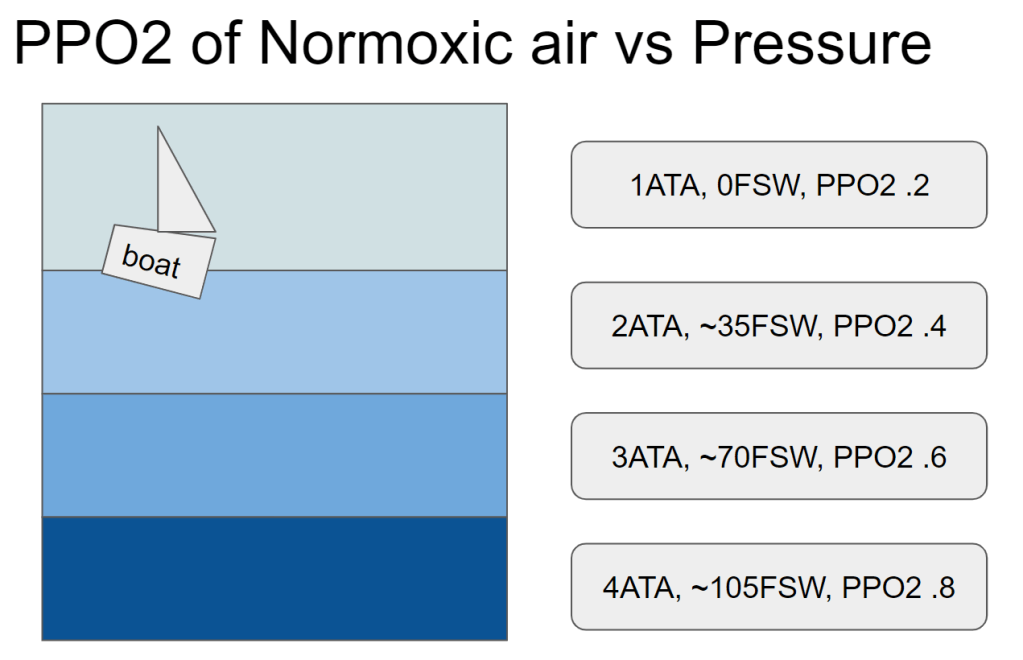
Instead, I intend to increase the PPO2 by increasing the pressure of the air- this will also prove out that the sensor works “at depth”. While that might seem magical, its pretty easy to imagine- as gas density increases at higher pressures, there are just more oxygens per volume bouncing around. The odds that one of these O2s bounces off the sensor go up as the pressure increases, and it is linear with depth.
The Science Junior
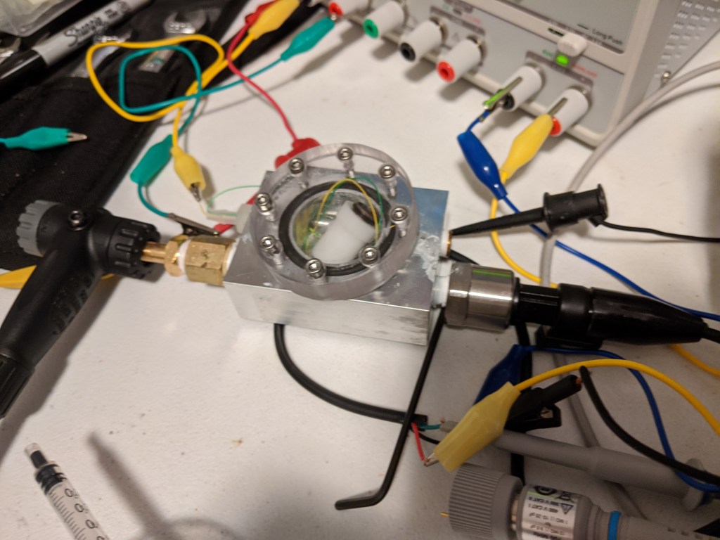
With this in mind, I set about what I am calling the Science Junior, since it looks like a generic science widget from KSP. Basically its just a small pressure chamber with a window and some NPT ports, which can be used for various purposes:
- Pressure port via schrader valve from bike pump
- Sensor wire pass thru
- Pressure sensor
- Gas infeed (?)
Construction
For those interested in the construction, the O ring is a just superglued out of cord stock and the sensor wires are run through a 1/8-27 NPT hose barb and epoxied in place.
Designed for a maximum pressure of 150 PSI, the 1/2″ thick polycarb cover and 8x M3 bolts should be more than enough to keep things together. There is about 1lbf per PSI so at 150 lbf I didn’t bother with the math.
One thing I would do differently is to use something removable for the sensor wire infeed, probably something that would get dropped in through the front and get captured by a lip on the inside, as shown in the sketch.
Testing and Learning
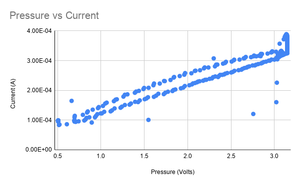
For testing, I set the bias voltage and logged the pressure (using a pressure to voltage transducer) and current of the sensor simultaneously while varying the pressure, which controls the PPO2. When the pressure is plotted against the current, it should be roughly linear. The chart above shows the sensor working reasonably well- however there is an odd drop of in current after being pressurized which manifests as a non-linearity in the chart above.
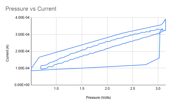
If we turn the scatter plot into a line plot to represent it as a time series, it looks a lot like a typical plot of hysteresis, but that seems like a red herring.
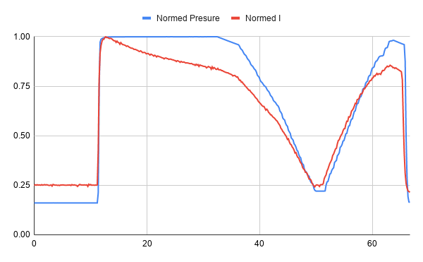
Looking at the normalized time series of the test, we can see that the sensor seems initially very linear, but then the current drops off after being exposed to pressure.
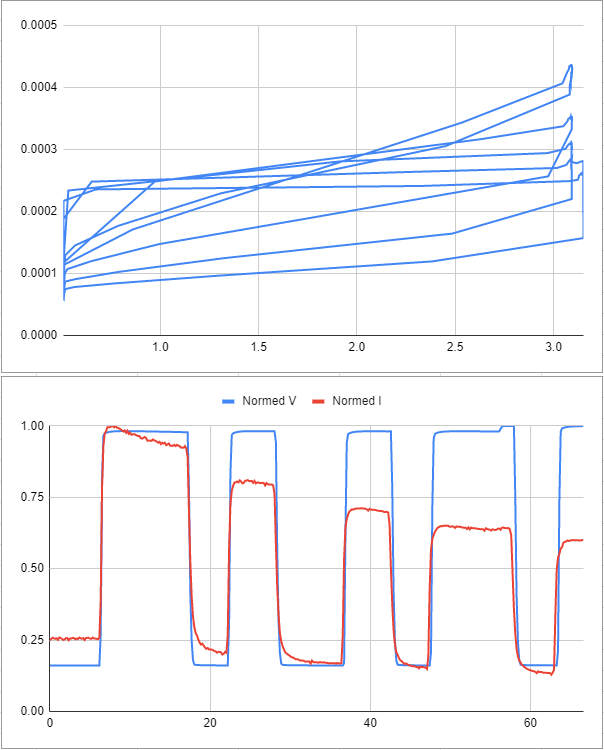
Here is some data from another test- the same strange trend occurs.
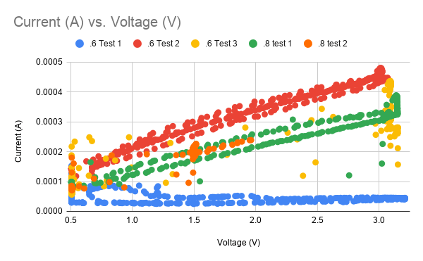
Looking at several sets of data we can see some that are complete garbage (blue data, yellow data, orange data) while some seem highly linear (green, red). Not exactly a good look for a mission-critical sensor that is helping you make life support decisions. Imagine trying to drive the speed limit if your speedo didn’t work!
Troubleshooting
I strongly suspect that pressure is playing a role here. First, sometimes gas is trapped under the sensor membrane, which causes the sensor to always read high, and to actually drop in current as pressure is applied. This seems to happen as the gas contracts and the membrane basically vaccum seals to the cathode. While oxygen is now coming into contact with the cathode, there is no opportunity for it to interact with the electrolyte, and this causes the current to drop.
Another factor is that in order to get the membrane closer to the cathode, I have had to burp out some electrolyte manually. This probably causes a slight negative pressure on the sensor as the membrane tries to regain its shape- I suspect that this can pull in gas and cause the gas blocking problem.
To solve this, I tried reducing the gap between the top lip of the sensor and the cathode, and making the sensors up “underwater” in electrolyte. This did seem to help with bubble elimination, but I still had a maddening and slow loss of current over time- uA over minutes or hours. these sensors show that good linearity can be achieved, but this drift is unacceptable for rebreather applications.
Additionally, I suspect that the sensor may not be fully watertight. That’s no good, since there needs to be electrolyte in there or it wont work! Some of the slow DC drift that I see could be due to this, or to evaporation through the teflon tape. The volume is <<1ml so even a small amount of evaporation could have an effect. I may try to remedy this or I may try to make a galvanic sensor…it turns out all I need is a little zinc or lead.
To be continued I guess!

One thought on “Oxygen Sensor and the Science Jr.”