I originally started by writing this post, but then decided to write a little more about the theory of polarigraphic O2 sensors first. This will skip most of the theory and just talk about how I built the thing.
Materials
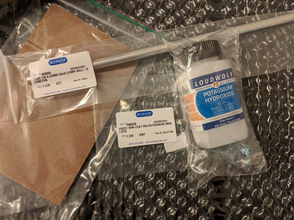
Aside from a few small wires and a small knob of delrin, this is what is needed for an oxygen sensor. A teeny chunk of platinum, a silver tube and Potassium Hydroxide (sold for making soap).
KOH Electrolyte
Based on some unscientific googling, I made up a ~4M solution of KOH because it seems to be a relatively common concentration. The electrolung used a .5 N (normal) solution and other papers quote 1 N solutions. For KOH, normality is the same a molarity, so I will need a much less concentrated solution in the future.
The three big takeaways here are that:
1) KOH seems to be kinda nasty stuff, and it should stay far away from your skin.
2) KOH is hygroscopic (picks up water), so it should probably be baked at 100C to remove water before weighing. I didn’t do this so who knows what molarity my solution really is- its “4M or below”
3) Mixing KOH into water is exothermic and also takes a while to fully dissolve. If you don’t know what you are doing, it seems best to let the angry little salts do their own thing.
KCl Electrolyte
After writing this and doing some testing, I found that KCl was also a fine electrolyte. 1-3M solutions can be purchased for a reasonable sum on amazon as dissolved oxygen (DO) cell storage solution. It would also be quite easy to make a solution of KCl, but I didn’t want to deal with dehydrating the salts.
KCl is my preferred electrolyte since it is more like salty water than draino. It feels a lot safer to be pipetting salty water at my desk vs super draino, and were I to re-do this I would skip the KOH for this sensor.
Fabrication Notes
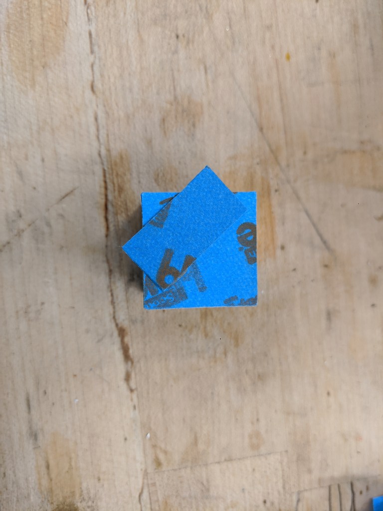
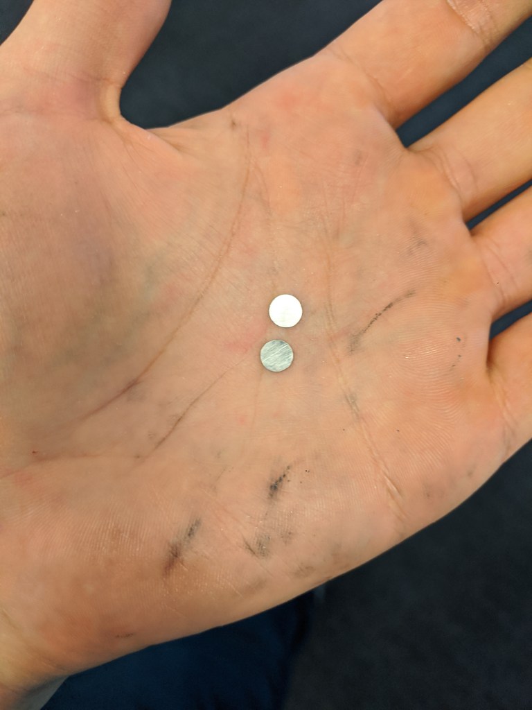
The 6mm diameter platinum electrodes were cut from a small sheet of 95% Pt 5% Rh from Rio Grande. Pt is surprisingly dense, and actually very annoying to machine for many reasons- it is tough, and compared to other materials, expensive. So to get as many parts as possible, I went with a “boring” operation using a .5mm 4fl carbide endmill with ~.00025″ chip thickness and .0015″ feed per revolution. I think that sawing electrodes out with a jewelers saw is probably a little easier, since my fixturing method (2 side blue tape + superglue) did not hold up to machining for one of the electrodes. Fortunately, I recovered that electrode with some filing (which worked very well). The short version of this is that there is absolutely no reason to CNC machine this stuff.
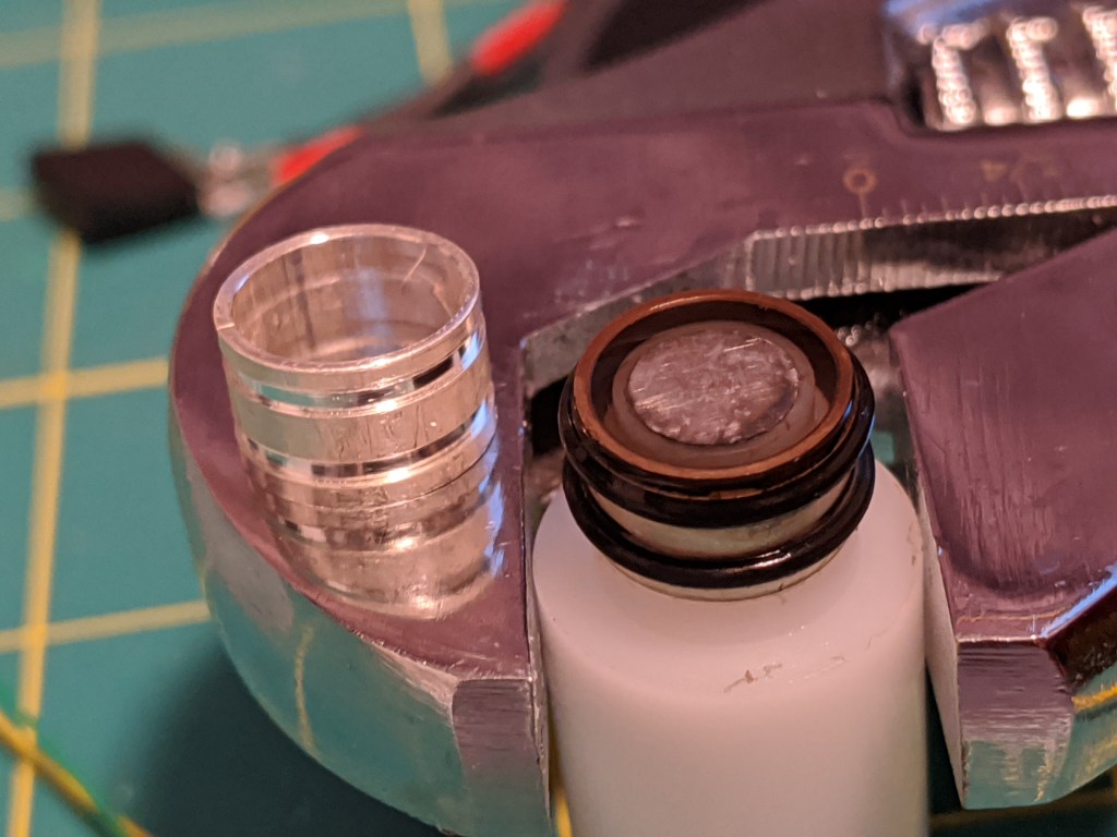
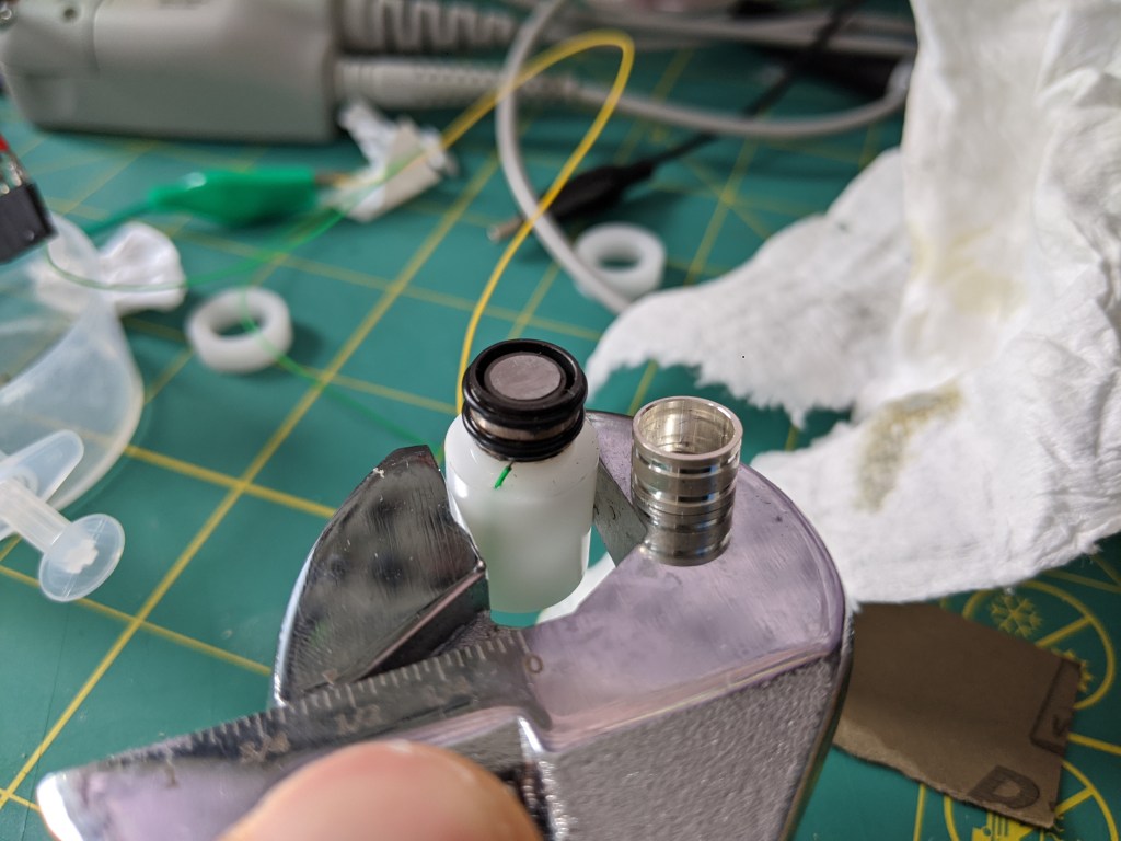
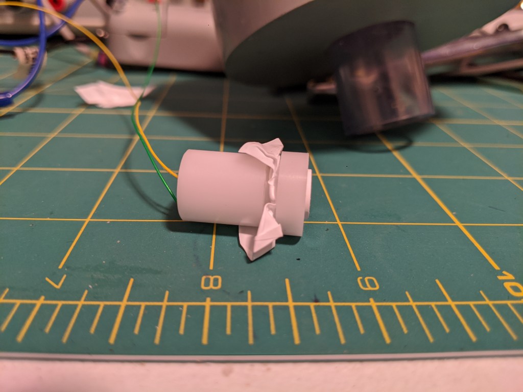
The silver anodes (999 Ag tube) were machined on a lathe. Aside from the fancy oring gooves, there’s no reason this could not be done with a hacksaw (gently, so as to not mess up the tube). Originally I wanted to use a rubber boot instead of orings, but that would have taken longer with what I had on hand. The electrodes are 6mm long with an OD of .375″ and an ID of .335″.
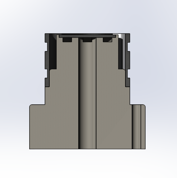
The body of the sensor was made of delrin. As you can see in the cross section above, there are some grooves here and there for things like wiring the Pt electrode as well as a pocket for the electrode. There is even a hole for wiring the silver electrode, which is not necessary (but it is nice).
Since the o-rings were a last minute addition to avoid finding and drilling a hole in rubber, I also made a delrin sleeve to fit over the orings and hold on the membrane.
Assembly
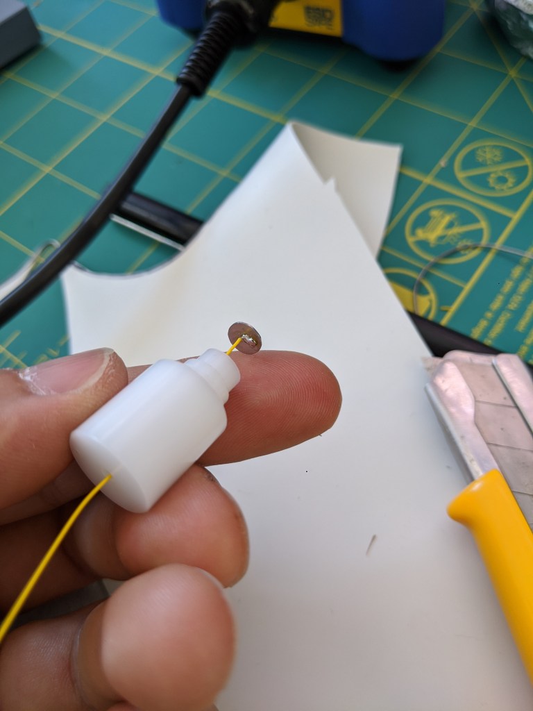
First a wire was soldered onto the Pt disc. This was done with normal SnPb electronics solder. This wire was run through the sensor body, and a dab of silicone was used to seal it to the body housing. NB these electrodes are pricey and a pain to make, but are also extremely reusable. Using silicone makes them more recoverable. For a “real” sensor, there is also room in the wiring hole to fit a thermocouple for temperature compensation.
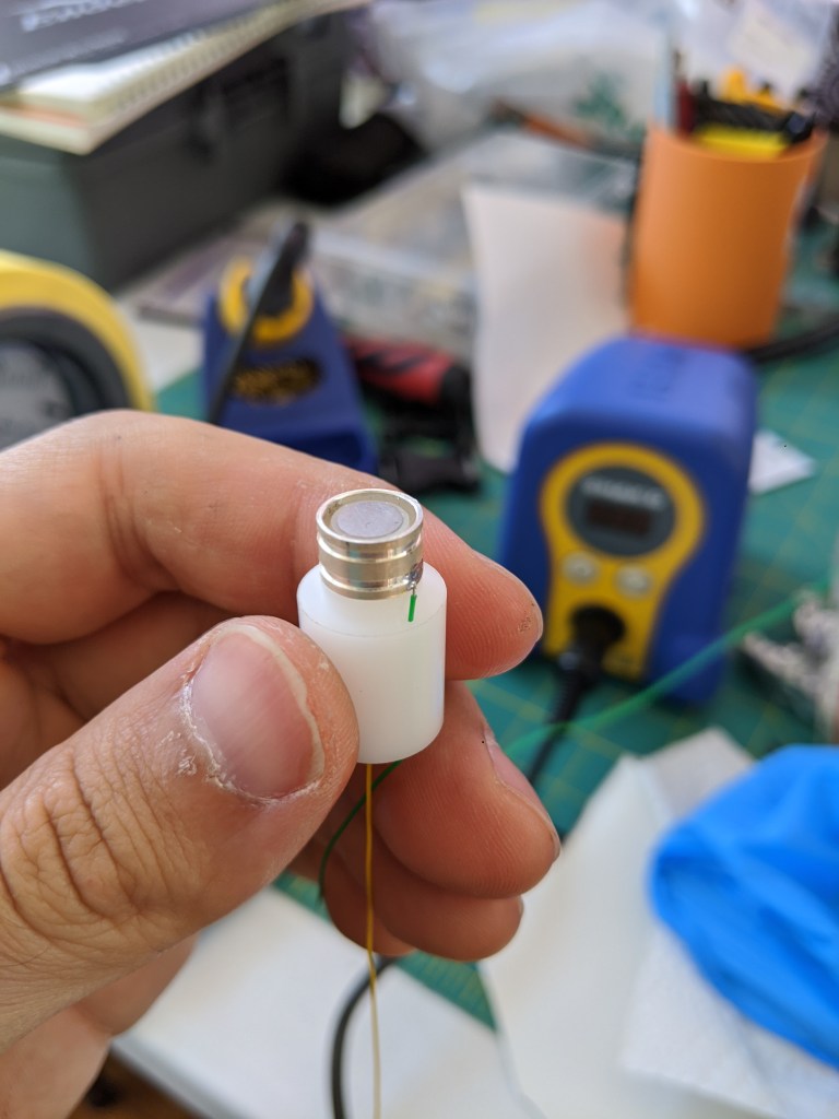
Next, the silver electrode was added, and a wire was soldered on. This extra hole gives me some pretty slick wire routing. NB this was done by sanding down the silver a little to get the solder to wet. I don’t think silver oxides are easy to solder to so this needs to happen before the sensor is used.
With the orings assembled, a few drops of electrolyte are added to the surface and a teflon membrane was stretched overtop, before placing on a retaining ring to hold the teflon in place (pinched between the orings and the ring). The “teflon membrane” is plumbers pipe tape.
Testing
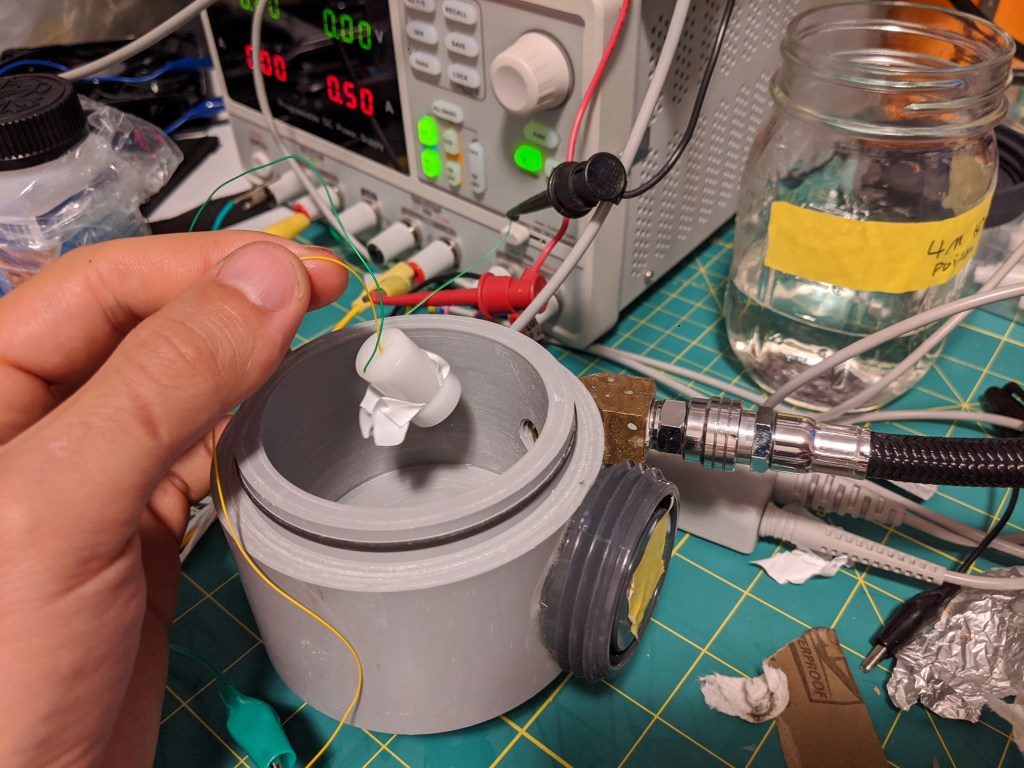
With the sensor wired up, of course I was curious if I had just completed an expensive art project or if I had actually made an oxygen sensor. Fortunately I had enough spare rebreather parts around to shoot some O2 at the sensor.
Initially I was disappointed because the sensor seemed to not do anything aside from operate like a galvanic cell that reacted to oxygen (see previous post). However, after switching to a very sensitive DMM (keysight 34465a) I was able to read uA changes based on O2 concentration with .6-.8 V of bias voltage. Typical current of the cell in air was very low- maybe less than 10uA. Blasting it with oxygen bumped it up to ~100uA. The response time was extremely low (immediate, as far as I was concerned).
I intend to do a little more work on this sensor, including improving the membrane, making up a proper electrolyte solution, and (of course) testing and temperature compensation. This kind of sensor is cool- unlike gold-lead galvanic cells, it seems like they can be revived with a little electrode cleaning and adding fresh electrolyte (kind of like sea monkeys). In the electrolung, they were actually hard-wired into the rebreather*.
According to the electrolung designers, they are also less sensitive to water covering the membrane. Another nice feature is that in theory, because they constantly consume all the O2 in the electrolyte, a polarographic sensor should fail low if it looses contact with the gas to be measured. This is more obvious than a galvanic cell that may have an O2 concentration “locked in” by water, which could make the PPO2 appear good when it is not good. A cell failing low will be an obvious indication that it has gone off the rails because if the cell reads 0 and you are still breathing, there must be oxygen somewhere.
To Be Continued…
*
This does not mean that is necessarily a good idea. The electrolung was not a huge success, in part because sometimes people drowned while using it. Additionally, to my knowledge, nobody has decided to use polarigraphic sensors in breathing equipment since then, although they are used for some really cool stuff like measuring cellular respiration rates and dissolved blood gasses.
