After a maddening time with polarigraphic sensor, I decided I would try to build the galvanic flavor of oxygen sensor. After reading this tech tip from Oakton Instruments, it seemed pretty obvious that galvanic cells have big advantages. The main draw for me was that the output was easy to measure, eliminating the need for the fancy DMM. This would also simplify the electronics needed for reading polargraphic cell.
Electronics Comparison- Galvanic vs Polarographic
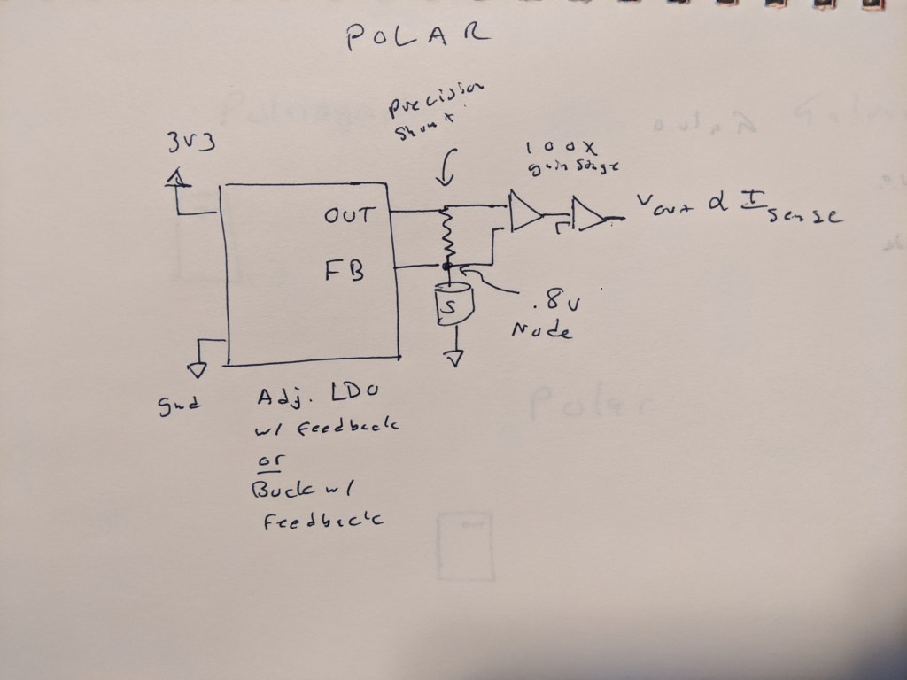
Here is what I think would be needed to read a polargraphic cell- a precision buck or LDO to bias the cell, with a feedback pin at the top of the cell. This eliminates the burden voltage of the shunt resistor that is fed into some kind of stack of op amps that then produce a voltage on the other side. This might not be so bad, and given that we have a 0 drop shunt resistor, we no longer need to worry about having a tiny burden voltage.
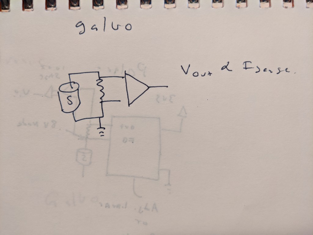
For a galvanic sensor, its pretty much as simple as it can be- a single resistor and a high impedance amplifier to match the voltage output range to the desired ADC.
Construction
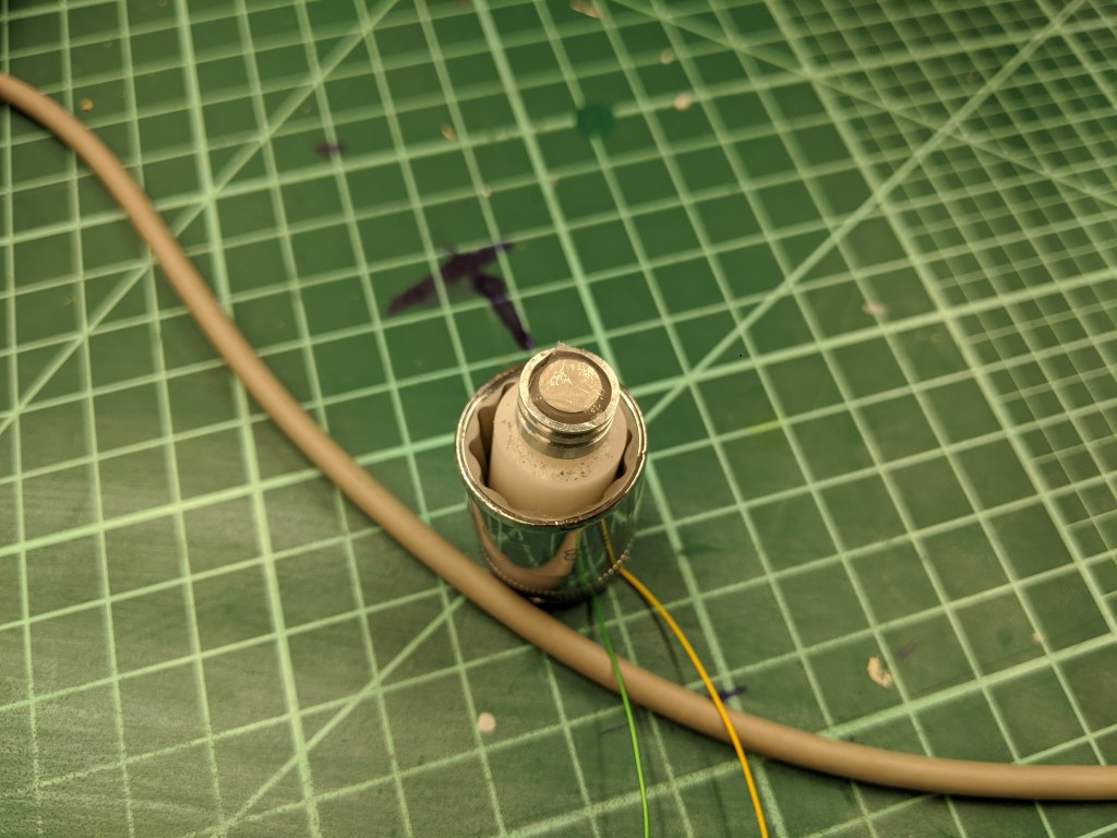
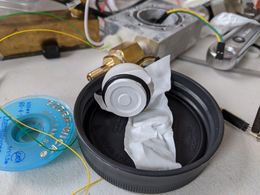
The first galvanic sensor I made just replaced the silver electrode with a zinc electrode. Platinum or gold (or likely any noble metal) makes a good anode for this system. Zinc, in contrast to silver or platinum, is a very, very agreeable metal to machine. I can easily take a millimeter or more off at a 25mm diameter. The rod I got from rotometals appeared to be cast, although without any apparent porosity after ~2mm into the diameter. The one offputting thing is that zinc fumes are toxic, and the melting point is alarmingly low~ 400C. So all the operations were done with a lot of coolant, and the soldering to the electrodes was done very gently to prevent or minimize any zinc vapors.
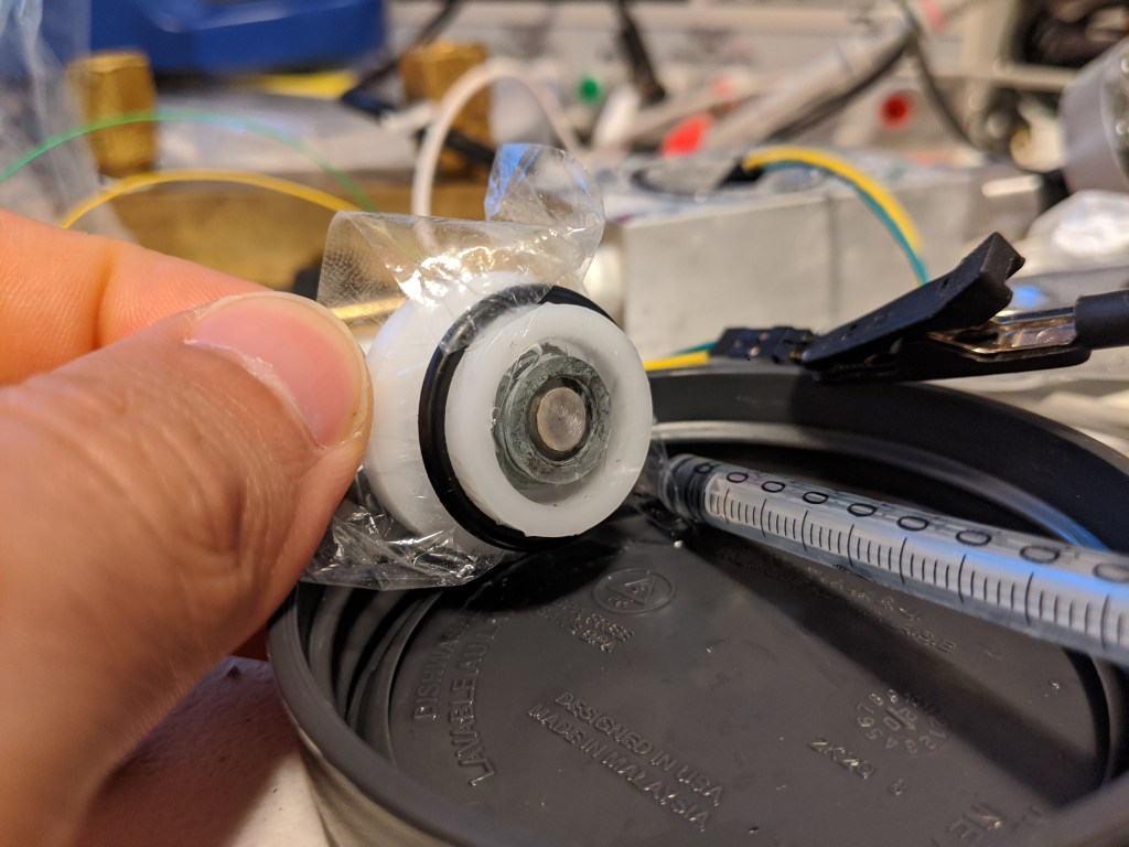
As you can tell from me stating that there was a first sensor, there is also a second sensor. The first sensor seemed to have the same drift problem as the polarigraphic sensor, which makes me suspect that the root cause of both sensors drifting is electrolyte loss through the membrane or leaking at the press fit of the metal to the delrin. I also wanted to increase the area of the zinc so that the electrode and the volume of the electrolyte. More zinc will alleviate any concerns about using up the electrode, and more electrolyte will reduce the impact of loosing small amounts of fluid, or bubbles. This is because each bubble or amount of lost fluid will be small compared to the sensor, since it is bigger.
Results
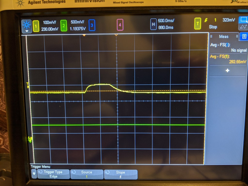
Much like the polargraphic sensor, it kind of works. It certainly can detect a change in the level of oxygen, but it does it in kind of a non linear way. For example, I would expect that if 20% air is ~300mV, pure O2 should be 5x that, or 1500mV. It is possible that the cell just cant generate that much current, and that I should try a smaller resistor, but I certainly have not verified that yet.
With the improved sensor body, the sensor was also a lot more stable. It dropped a few mv over a fw hours, and its hard to know if that was related to temperature, drift, or the actual O2 concentration in the room. However, this stability was achieved over ~30 minutes as the sensor reached equilibrium. Likely the O2 in the bubbles in the electrolyte needed to be used up first, as they are in direct contact with the electrolyte. I suspect that after that happened, the sensor reached equilibrium with gas diffusing across the membrane and stopped sensing O2 trapped in the sensor.
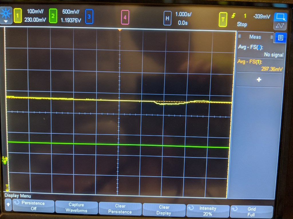
On the other hand, it does seem very sensitive. Breathing on the sensor produces a small dip, and there is a noticeable difference in value (~30mV) from when I sit right in front of it and breathe on it vs when I leave the room- this is mostly anecdotal but interesting.
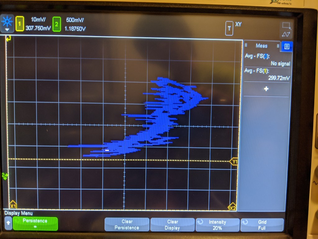
The linearity is not very good, as you can see. This is a plot of the pressure transducer vs the sensed voltage. Its all over the place, but is vaguely the right shape. Ideally the sensor should trace a straight line here, but there may be some hysteresis that causes non-linearity.
Unfortunately, just like with the step response, the change here should be much bigger. This test pressurized the sensor from 1 bar to roughly 6 bar- the reading should be about 6x as big, but it only went up a few mv! So this is not that impressive, as it shows either a non-linear sensor or some kind of enormous DC offset.
The last issue seems to be that the sensor leaks somehow. It may be that water vapor is permeating the membrane, because when left overnight the sensor dried out. In a humid environment like a rebreather this may not be a issue, but for storage it certainly is. This answers a question I have had for a while- why are rebreather sensors so slow? They are rated to a rise time of 6s to get to 90% of the final value. This is much slower than any of the sensors that I have seen, and does not seem to be an inherent characteristic of the sensor. My suspicion is that a much thicker membrane is used on rebreather sensors to reduce electrolyte water loss.
Semi-Conclusion
This sensor seems a lot easier to use, but it seems like a lot of the issues I have noticed may be due to my membrane selection and leaking. I have parts on order for a larger pressure pot (the under $50 cell checker) to see if I can get the larger sensor to behave in a linear way with a polyethylene or FEP (or even teflon tape) membrane. I think this cell checker will be very useful for a number of other things like depth gauges/computers/ingress testing so I am excited to have it on hand. I will have to make an effort to keep my pressure pot electrolyte free this time!
