If I had a dollar for every time someone tells me I’m going to die using my oxygen rebreather, I would have about $6. However, I did royally freak out two local divers who were mystified by how I could use a rebreather and not know my ppo2. While I kind of know my PPO2, I thought it would not be a bad idea to actually measure it. And with O2 sensors in a global shortage, and with a smidgeon of knowledge from rebreather history, I figured I would try to build my own. This has turned into a much bigger project than I expected initially, and the project is certainly not done, but I have learned a ton about oxygen sensors.
History: The First PO2 Sensors
1969 is when Walter Stark and John Kanwishwer introduced the ‘Electrolung‘, which was among the first electronically controlled rebreathers. It seems like it was the first time that one could really know their PO2. John Kanwisher had recently improved the Clarke Electrode (1962, used to prove that extracorporeal oxygenation works), creating a non-fouling oxygen sensor by using a teflon and polyethylene as an oxygen permeable membrane to protect the electrode.
Construction of the Electrode
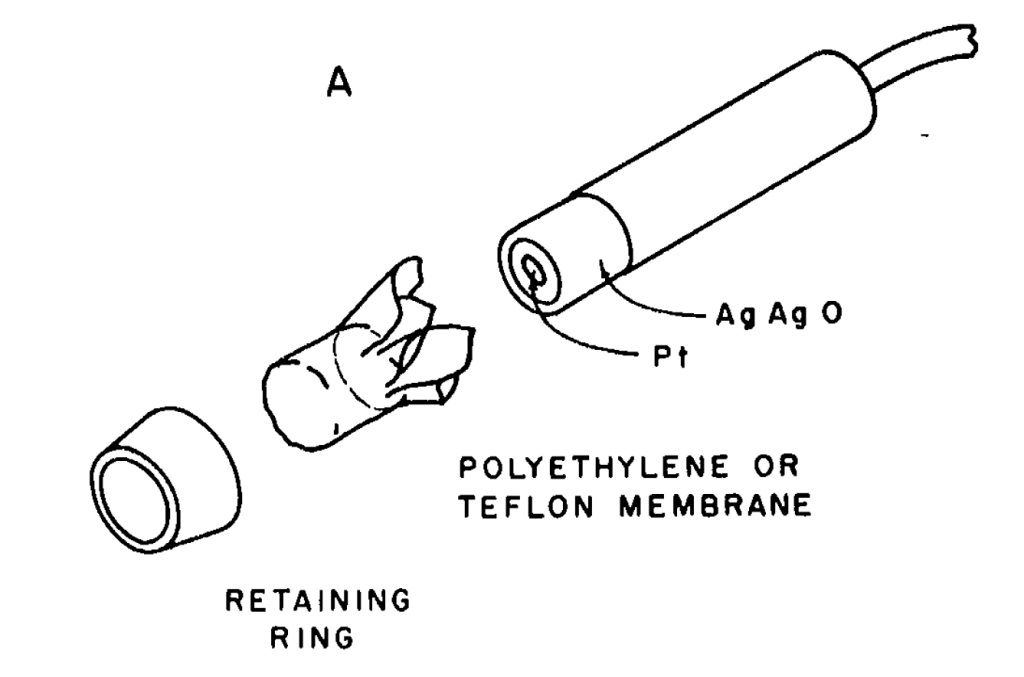
Mechanically, as you can see, the electrode is pretty simple. A Platinum disk with a silver-silver oxide electrode is covered by teflon, after trapping some KOH electrolyte underneath it. Less simple is the reaction. As I understand it, at the platinum electrode, dissolved O2, water, and electrons from the bias voltage to form hydroxides. At the silver anode, silver and hydroxides form silver oxides and electrons. One difference between the original clarke electrode and modern electrodes is that modern cell use KCl. Both certainly work, although KCl makes AgCl instead of Ag2O. I believe the reason for this switch is that KOH solutions are very chemically active and will turn people into soap, while KCl is a lot less active. Oddly both are food additives, although KCl has an LD50 of about 10x that of KOH.
The original paper suggests sticking the whole sensor into a vat of KOH solution and capping the sensor under the solution, so it seems a lot less scary to do that with salt water instead of a strong base. I hope they wore gloves (but I suspect they didn’t)!
Most importantly- it is key to understand what dissolved O2 is supposed to do in this sensor- it allows current to flow with a bias voltage across the cell (variable impedance), unlike a galvanic cell which causes current to flow (fuel cell/battery).
Observed Sensor Behavior
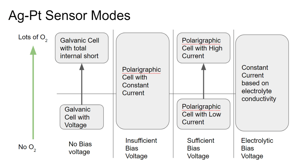
This type of oxygen sensor seems simple, but there are some subtleties that make the behavior a little difficult to understand. Below I will try explain some interesting observed behaviors of the sensor, and why these things happen. The chart above is a handy key to the rest of this post, which will discuss what happens as the bias voltage on the sensor is increased from 0V.
No Bias Voltage (Galvanic Mode Pt-AgAgO cell)
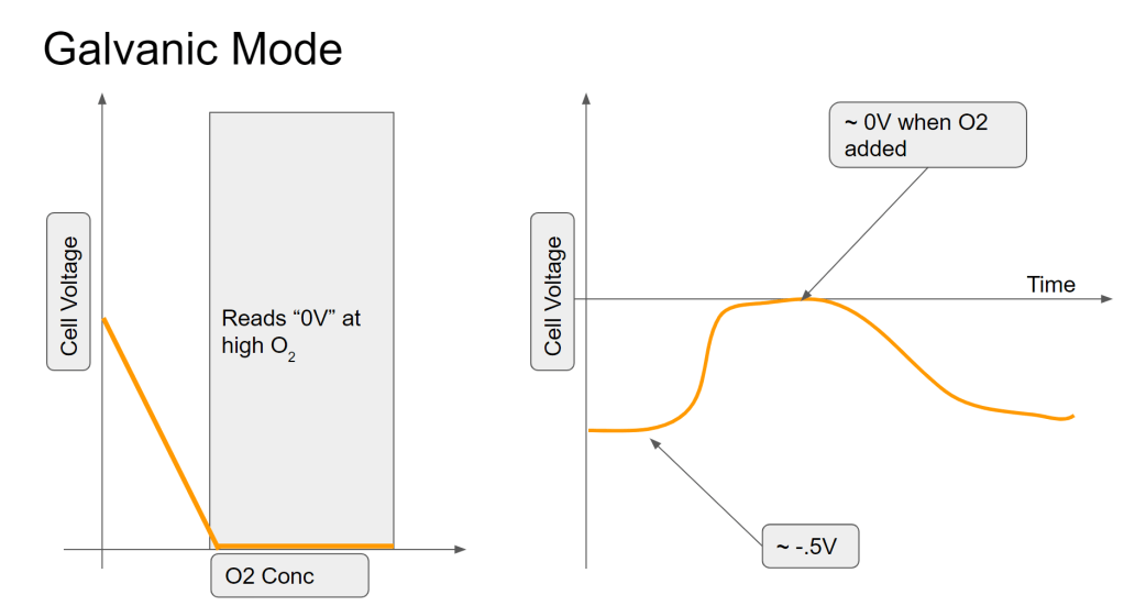
In this mode, the sensor is producing a voltage instead of a current. As most people know from things like potato clocks and glavanic corrosion, two dissimilar metals in an electrolyte will tend to produce a voltage (across the metals). Based on my measurements and not my knowledge of chemistry, it seems like it is still the case with this cell- a small voltage (500mV) is produced between the Pt and Ag in the electrolyte. However, when exposed to oxygen, it seems like that voltage is reduced, probably by discharging the accumulated charge (voltage) back through the electrolyte. This can be considered an internal short across the electrodes of the electrical cell. However, measuring oxygen based on the blocking of this charge accumulation (voltage) does not make for a good sensor and since the voltage source is very weak, has a long recovery time (minutes/seconds). It also reads 0V (saturates) below an amount of oxygen that is useful to measure. In other words, the readings get clipped below the O2 fractions that would be useful.
Insufficient Bias Voltage (constant current)
In this mode, there is enough oxygen that the cell produces a constant current, since the “use” of the O2 is much slower than how fast the O2 is replenished. This mode should be avoided for sensing since an increase in O2 will not be noticed, since the O2 in the cell is always not depleted.
Sufficient Bias Voltage (Current proportional to O2)
In this mode, the voltage is high enough that O2 is immediately used when it enters the sensor. Therefore, the current that is produced is related to how much O2 is moving across the sensor membrane. This is the “sensor” mode of a polarigraphic O2 sensor. Again, if the size of the electrode is too small or if the membrane is too large, at high O2 concentrations the O2 diffusion could possibly catch up to the current and saturate it.
One interesting thing is here is that when the bias voltage is switched on, there will be a large spike in the current for a short time (<1s) before it settles into its “sensing” current. This is the current produced when the dissolved oxygen in the sensor is initially depleted, and it can be large- on the order of 1000s of uA (~1 mA)! If operated in the insufficient bias mode, this spike will not be seen.
Hydrolysis Bias Voltage (Constant current)
At this voltage, the water in the electrolyte will start to break apart and form gas. I would imagine that the current here is dominated by the conductivity of the electrolyte, but I haven’t made any measurements here.
What the heck is a Polarograph?

That’s a good question- the polargram is a representation of the sensor output, so called because it measures the response vs the electrode vs. the polarization voltage. The chart above shows what we should be able to measure with the sensor.
What O2 Sensors Really Measure
In the sufficient bias range, more oxygen speeds the reaction and therefore increases the current. Current is proportional to the dissolved oxygen in the electrolyte, which should be limited by the diffusion across the membrane and the size and proximity of the Pt electrode to the membrane.
Polarigraphic and galvanic lead-gold sensors are sensitive not to oxygen mass or oxygen fraction (% makeup of gas that is O2), but essentially measure the rate of diffusion across the membrane (assuming they are working right). This is then calibrated to some known O2 concentrations, usually two of whatever is conveniently available- 0% (nitrogen purge), ~21% (air) and 100% (O2 purge).
This diffusion should be related to the prevalence of O2 in the sensed gas or liquid. Normal air, at a higher pressure, will have a higher availability of O2, and O2 will diffuse faster. Oxygenated media flowing by the sensor will have a higher availability than non-moving media. Temperature will also affect gas solubility and diffusion.
Oxygen Gas Sensors for Diving
For diving, the pressure plays a large role in O2 sensing. As breathing gas is compressed, the pressure increases quite a bit (up to about 4x pressure at recreational limits). When divers talk about oxygen sensors, they really are talking about measuring the oxygen partial pressure. Given some container and gas mixture, a partial pressure is the pressure a gas would have if it were allowed to take up the whole container without the rest of the gas mix. Surprisingly (or not) the sum of the partial pressures equals the pressure of the whole mix.
For nitrox-savvy folks, reading PPO2 at the surface works out easily to O2 fraction (% of gas by volume) since the oxygen measurement is happening at the surface at 1 ATA. For nitrox, this PPO2 is then used to figure out how deep you can go (increasing PPO2) before you hit a maximum PPO2 limit.
For rebreathers applications, the thing that is interesting is direct reading of PPO2, so there is no need to convert to O2 fraction. As pressure increases, so does partial pressure of oxygen, creating a higher pressure differential of oxygen across the sensor membrane, resulting in faster diffusion, which is then sensed.
