About two months ago I had a hankering for a personal 3d printer- one that I could fix and break at home, instead of just fixing the ones at work. Like many engineers, I was unable to decide on buying an off the shelf, already functional printer- no instead I decided to buy a delta printer- specifically the cheapest one I could find, the FolgerTech Kossel. No, you cant have the link. If you want to buy one too, you will have to figure out how yourself- if you can’t do that, it is unlikely that you will finish the kit. Read on to find out why. See my summary at the end if you don’t want to read the long form post.
NB: at the time of posting this, the kit has been changed a little bit, but I expect the quality and service are about the same.
Unboxing

The general unboxing experience was pretty awesome. It is hard not to be excited when you get something like a 3d printer in the mail. Smaller items were sealed in little bubble mailers with labels on them, while larger items like the rails and the extrusion were taped together with “kaptan tape”. One extremely annoying and totally frustrating thing was that the screws were all mixed together. It seems like it would have been easy to separate out the ~10 types of screws into different bags, and in fact, it seems like folgertech took all the separate parts and then mixed them together, making it worse for the person who has to assemble it. Boo.

Fortunately, I had enough film canisters and petri dishes laying around to sort each fastener, bearing, and washer into a separate bin. Hooray!
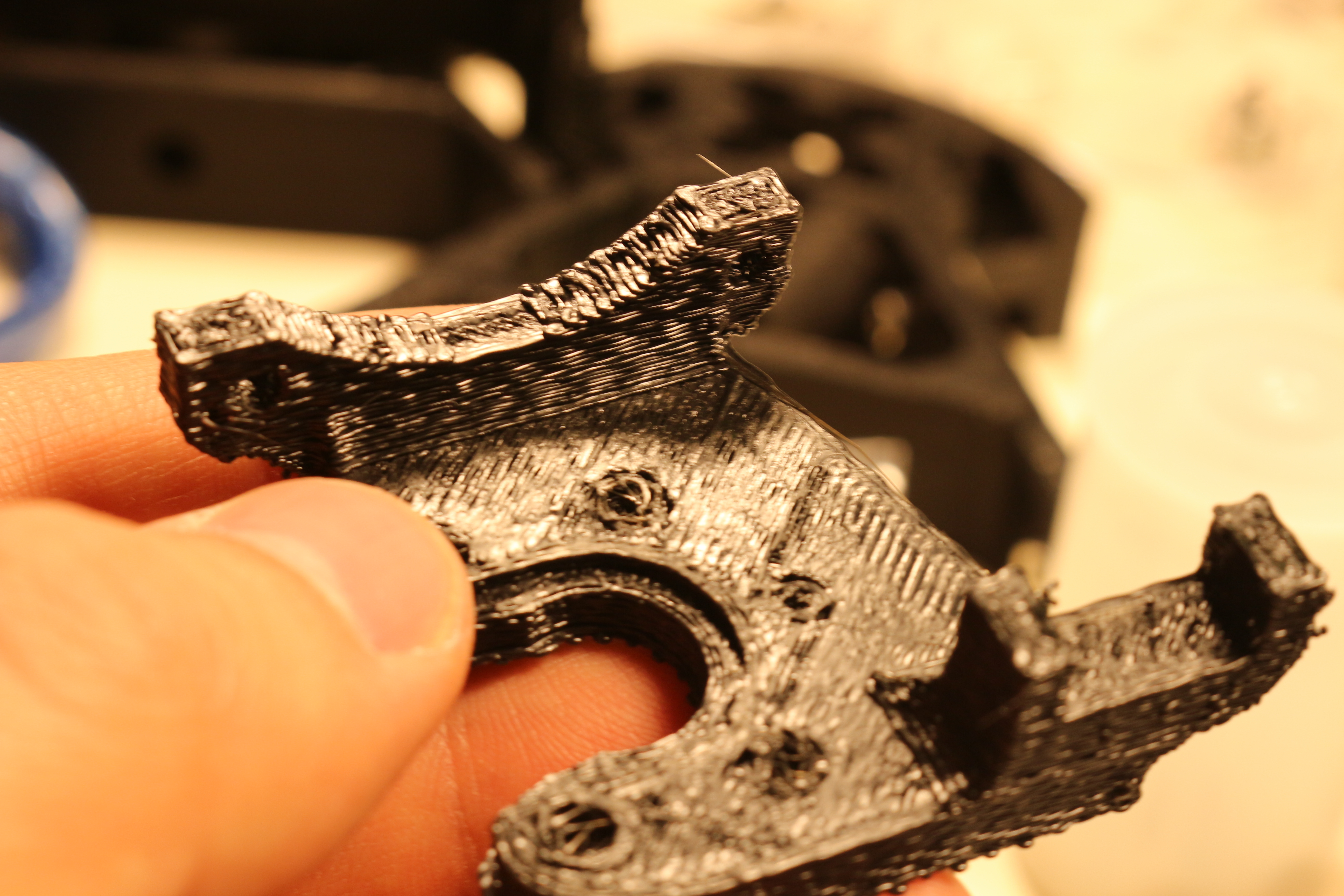
A note on the general quality of the kit seems appropriate here. Most of the non-printed parts are of acceptable quality. By this I mean that there were 1-2 defective screws, and after lubrication and cleaning, the linear bearings seemed ok. Some of the parts were of totally unacceptable quality and will absolutely need to be replaced by the user. I have a complete list later on of things that I had to buy, but the worst offenders of quality were:
-The hot end platform was completely useless, burned, and blobby. They clearly did not use support and the cantilevered parts suffered because of it
-The end effector was similarly scorched. It looks like a z axis/bed leveling problem
-Despite the massive 14 AWG (.064″) cables for running the high current DC to the heated bed, the AC power cord is maybe 30 AWG (.010″) stranded, and it heats up noticeably when turning on the printer. I worried that when I ziptied it to the frame, I would pinch off the flow of electrons. It is also not IEC color coded, which means right now, it is possible that my machine is grounded on the wrong side of the fuse.
Assembly:
Assembly was not difficult, aside from the poor print quality, shoddy instructions and missing pieces.
According to the kossel BOM, you need about 100 m8x3mm screws to complete the printer. I was shipped 36. After complaining, I was shipped another 36. While I was impressed that they shipped me the screws, I was not impressed by the fact that I was still 28 screws short of the full 100. Fortunately I had already ordered backup screws from McMaster Carr. This took about four days, since it was over a weekend. I could have easily built the printer over that time, but I was $4 short in screws.
The print quality of the components is also quite low. The infill is decent, but it seems like their extruder had some difficulty keeping up. As a result, the prints are extremely vulnerable to de-laminating. This complication is compounded by the prints not being properly sized to fit the extrusion through them- this means that as you push in the extrusion, it is trying to tear apart the print. Fortunately, I got mine together with only slight damage, which should allow me to print new brackets at a later date.
Print quality issues also caused some problems in holding nuts, which screws were supposed to thread into. Coincidentally, all of the holes that should have been clearance holes actually being interference fits for the screws, so I could screw them in with no nuts. A few of the parts (the end effector parts) I had to re print, as the parts I received were unusable.
Now that we have covered the problems with low quality and missing parts, we can talk about the instructions, which for the most part are usable. They are not well lit, high quality, or in focus, but they are usable. What was totally unusable was that the instructions conflict and were apparently not shot on the same model of machine. There are extra stepper drivers, wires, and connectors that are not wired in the printer, but do show up in the pictures. To add to that, the limit switches are shown wired in such a way that when the switch is not closed, it shorts 12V to what seems to be the arduino ground, which is not the greatest thing to do for many reasons. As a note, this makes the arudino drop off the USB, so if you see that check your endstops.
Troubleshooting/Small Electrical Fires:
Of course, none of these problems prevented me from eventually building and testing the printer. And then the real fun began! If I started a print with these lines:
M190 S105 ; wait for bed temperature to be reached
M104 S235 ; set temperature
This would result in the bed temp going up to 105, and then the hot end temp would go up to about 100, then crash. Slowly, the bed temp would go down after that, until they were both at 25C (my room temperature). It seemed like an electrical problem, so I checked the power out of the power supply, which was good. Next, I checked the temperature of the board. Surprisingly, they were very very hot. At this point, the MSTBA connector started to make smells, smoke and melt, which led to me unplugging the printer.
The problem was that the polyfuses had blown, and some combination of the polyfuses heating, the FETs heating, and living under the heated bed had caused the plastic of the connector to heat up and short the 30A 12V supply. In retrospect, it was probably that the board was mounted with metal screws (as per the instructions). The RAMPS wiki page says “DON’T secure Arduino/RAMPS with conductive screws through both mounting holes. The screw may cut into the positive trace creating a HIGH current short.”. Either way, this was not good, and totally the fault of the instructions that folgertech provided. Using non-conductive nylon fasteners might be one way to fix this.
I disconnected all the electronics and moved the controller out from what was essentially a 110C oven. I oriented the heat sinks and polyfuses facing up (as they should be) in open air, instead of in an oven. With the connectors extended, the terminal block plug connector removed and with wires soldered in place, I powered the printer on and much to my surprise…it printed!
Print quality:
Considering that the printer is held together with zip ties and given the generally low quality feel that I had as I put it together, my expectations for this printer were low. However, I have to say that it has performed admirably so far. It is extremely quick, and with a 1″ calibration cube (printed in the center) I measured that it was within about .005″ (that’s 120 microns for you metric people). This is without bed leveling, or really properly tensioned belts or anything, so I am pretty pleased.
NB: after further prints this turned out to be a fluke, the Z of this print was pretty far off.
Summary:
Count this as more of a box of parts, some of which you may be able to put into a usable printer. The cost of the kit is about $350, but expect to need to spend another $50-100 on parts that you didn’t expect to need, but that you will need (and that will slow down your build).
