
The flash acting as a thermometer. Also pictured, FTDI friend and discovery board aka stlink programmer
In my last post about the Flash, I showed all the LEDs lighting up, but I really did not have the board mapped out or the toolchain set up yet. I just went on mbed, and turned all of the outputs on and off, a condition pretty much guaranteed to blink some LEDs on the board.
I wanted to do something a little more involved with this board, so I took the time to reverse engineer the connections and figure out to talk to the sensors and I/O elements on the board. I have figured out the LEDs, the button, the internal temperature sensors, and the accelerometer.
LEDs
This one was tedious, but not hard to figure out. I knew all the LEDs would turn on, and that it was not likely to hurt anything if I had all the pins high. All I had to do here was write a program that turned one pin on high at a time, until I had a map of pins to LEDs. I was surprised to find out that the NRF was actually not sourcing the current to the LEDs- meaning that when the pin is low, the LED is on.
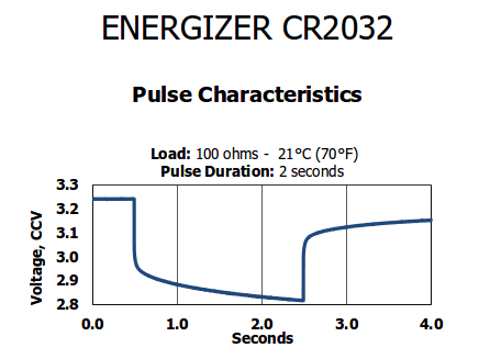
For about .5 seconds, the battery can source ~33mA
I am not 100% sure why they did this, but my theory is that they found out that you can sink slightly more than the advertised current into the chip, and that the driving output is pretty limited. According to the datasheet for the energizer CR3032, it looks like it can provide 33mA for a few seconds before some serious voltage drooping sets in. It also seems like trying to output more current might drop the output voltage more, while low side drive might guarantee a lower voltage (and therefore a bigger voltage drop, and more current across the LED).

The current the original firmware drew when doing an LED animation
This is a recording of the current drawn from a 3v power source by the device using the original firmware, with the LEDs on. You can see that they were very careful to use a lot of PWM (about 50% duty cycle) to keep the average current low, but the instantaneous current got as high as 30mA!
Once I figured out what went where, I made a nice little animation that turns on all the LEDS starting at 12 o’clock, and added them to a custom flashboard.h header so it would be easy to reference and compile everything. I did this a few too many times and ended up killing my battery! But I also found out ALL the LEDs can be on.
Button
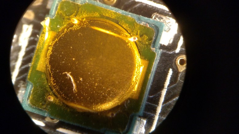
What a nice little dome switch
The button was also tedious, and I ended up not figuring it out on the first try. My initial approach was to run my clock animation any time the button was pressed, pulling the button high, and waiting for it to go low. Unfortunately, this did not work quite right, because the button was already pulled high by an external pullup. This made it pretty tricky to find the button by looking for a response when the button was pressed. Eventually I just looked for connections on the board, and then tested a few likely candidates for voltage drops when the button was pressed. I also found what looks like a voltage divider, which may be used for measuring battery voltage (but I am not sure yet).
Temperature

It is toasty in there!
The NRF51288 has an internal temperature sensor, which I decided would be fun to print out over the UART. It seems ballpark reasonable, as it settled on about 42 or 43 C for my body temperate- but it may be generating a bit of heat on its own. It is a cool “free” addition to the board.
Accelerometer

CS: 2 MISO: 5 MOSI: 4 CLK: 5
After a bit of poking at registers, I wrote a little SPI routine to talk to the accelerometer on board. After I made sure I could read the WHO_AM_I register, it was easy to get the rest of it working. Figuring out the pins for this was super easy, because they are labeled on the board- I just looked at where they went and I was right on the first try! I even got CPOL and CPHA right.
Things I might make
Well, now that I have all this stuff working, its time to make this into something else and call it a day. There are a few ideas I thought would be worth a try:
- Digital plumb bob- the bottom most LED would always light up as the device was rotated
- Digital marble- simulate a marble or a drop of water that “settles” at the lowest point
- Vibration logger- how often are doors opened? when does the HVAC run? when are toilets flushed?
- Height sensor- detect free fall, and count how long before hitting the ground

HI, Your website is amazing and your blogs are very informative. I just wondering that what is Accelerometer sensor is used on board with NRF51822 module. I understand that accelerometer sensor is interfacing with an NRF51822 microcontroller is SPI communication. It would be great, If you share pin connection of this module like which pins of the nrf microcontroller is connected to buttons, LEDS, Accelerometer sensors. Thanks in advance.
Off the top of my head, it is the LIS2DH. If you look on GitHub, there is a flashboard.h that has all the defines for what pin goes where.
Thank you very much.