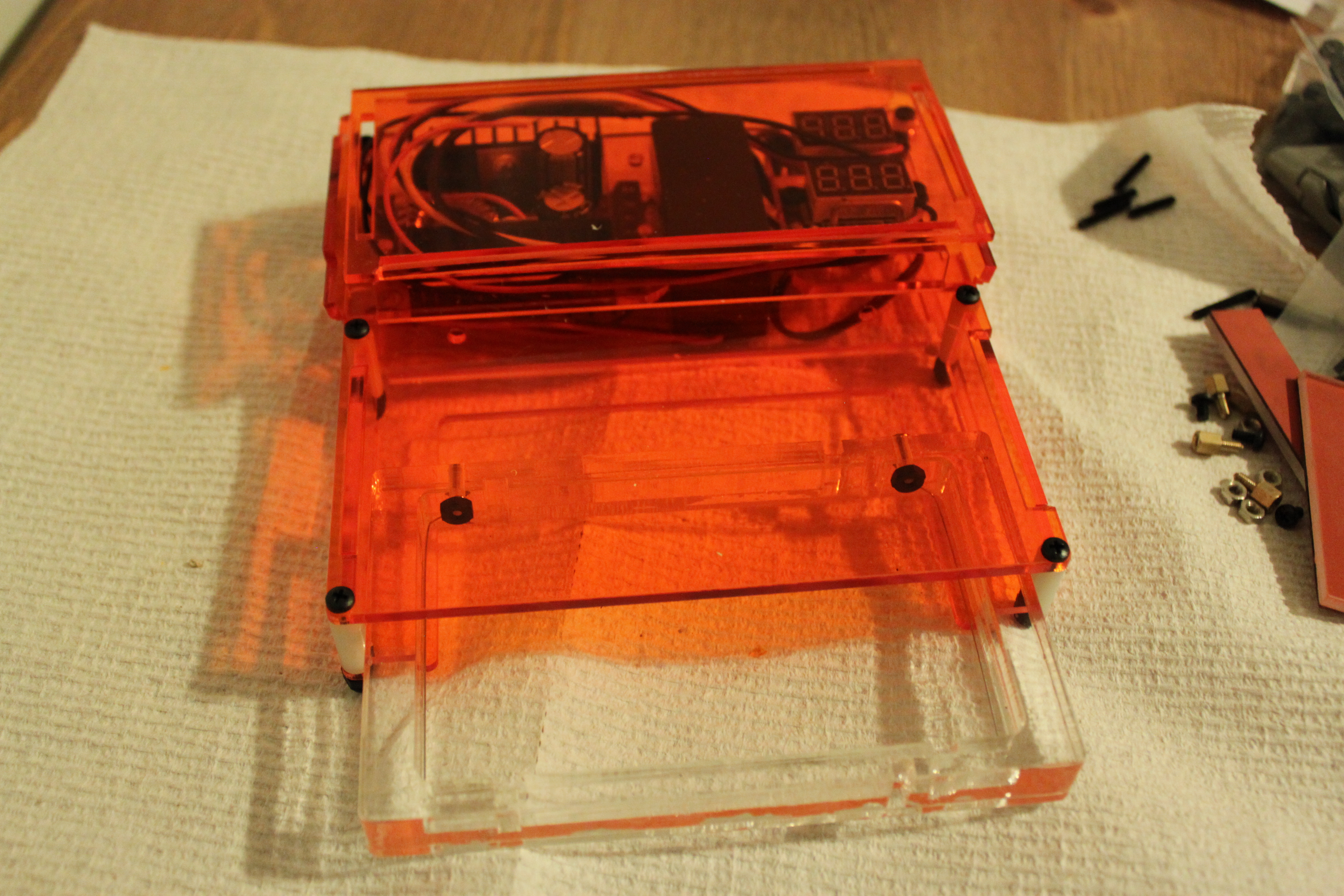
The second prototype! Fingers crossed, should be done in one more revision.
Gel Boxes should be beautiful. Actually, all lab equipment should look awesome. Here is the second revision of the plastic hardware. It is almost correct. Some of the cutouts for the electronics are too small and caused cracking. I also got confused and made a “revision” with some cutters that I regretted- the part was actually made correctly, but I freaked out and cut it. I need to revise the holes for the cables, and make the roof taller as well. Right now it is not fully wired, up but the really key thing is making sure the laser cut portions are spot on- I have validated the sketchier functions on the first prototype.
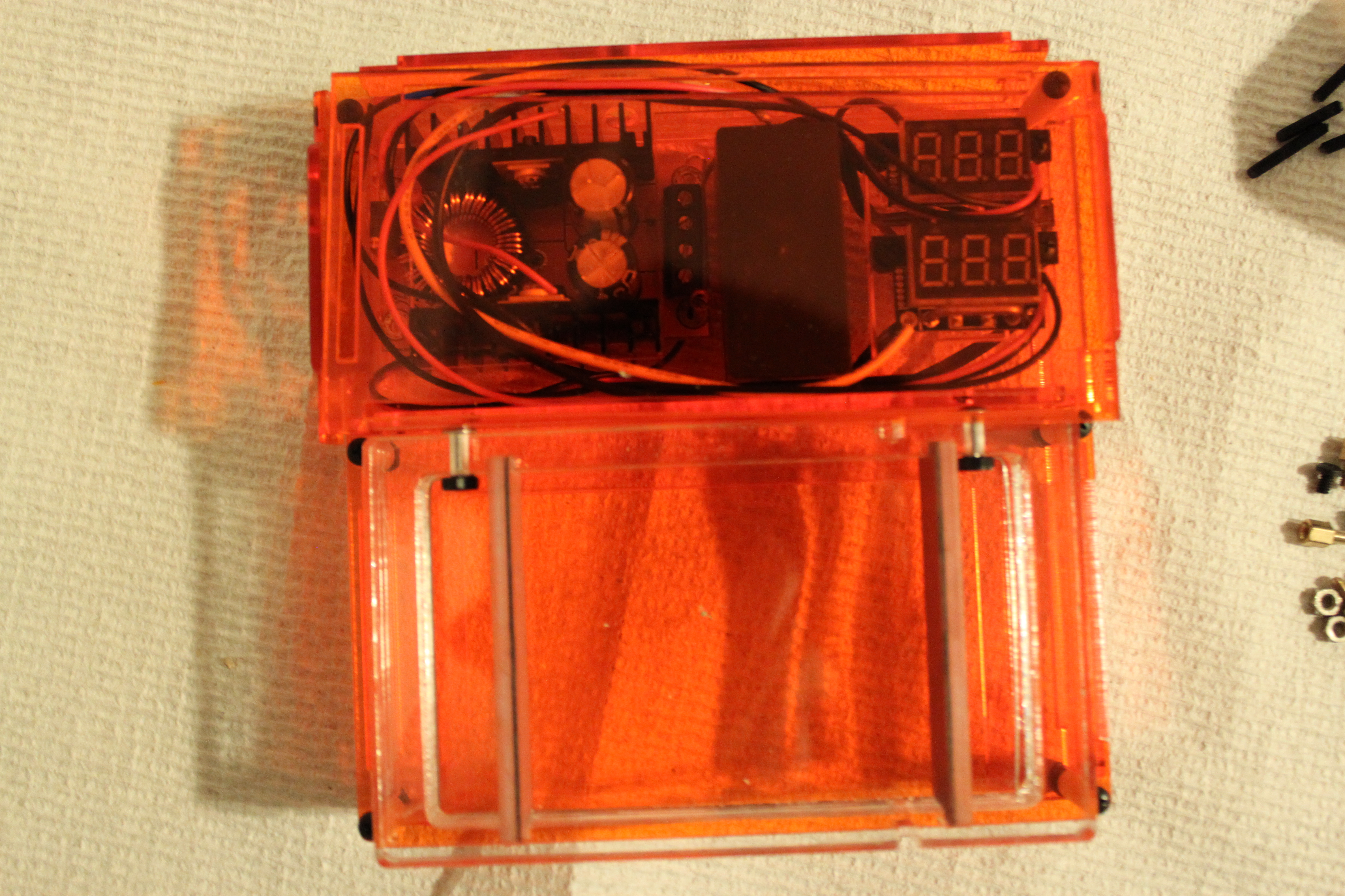
Here is a top view
Alright, lets talk electronics first. Crammed into the back portion of the box are brains and brawn of GelIS. That thing with the heatsinks on the left is a 12V to 30-90V boost converter. That means that 12 DC goes in, and something between 30-90V comes out. If you look carefully, it is actually in backwards (rotated 180) from what makes sense, because those screw terminals should be on the side of the box. This was a fabrication snafu.
This shape brought to you by cartoon mouse doors.
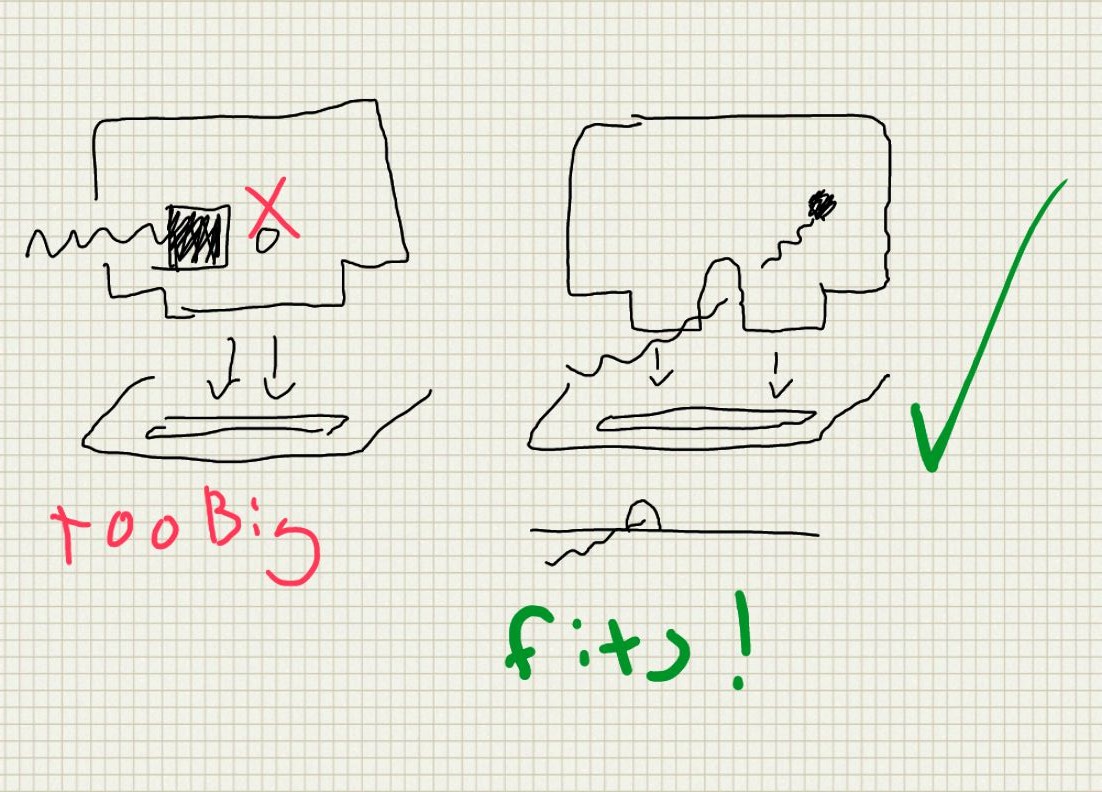
In the middle is the power supply for the EL panel illuminator. It is also powered off 12V, and the cable to the illuminator comes out the back. Right now there is a circular hole for the connector, which totally doesn’t work. This prototype helped me figure out how to run that cable, which has a bulky connector on one end from inside to outside of the box, which is summarized in the above sketch.
Finally, on the right are a voltmeter and ammeter. You need these if you are going to run a gel, and I haven’t seen many DIY kits that include them. “hook a multimeter up” is a bad option because you need both voltage and current, which means two multimeter, and probably some sketchy connections. This shows both, simultaneously. The sketchy source of these suggests that they refresh “at about 200hz” which is plenty fast for us. Unfortunately, they also make the box look kind of like a cartoon of a bomb. Better put this in the checked luggage.
#forgotthecombatthelab?
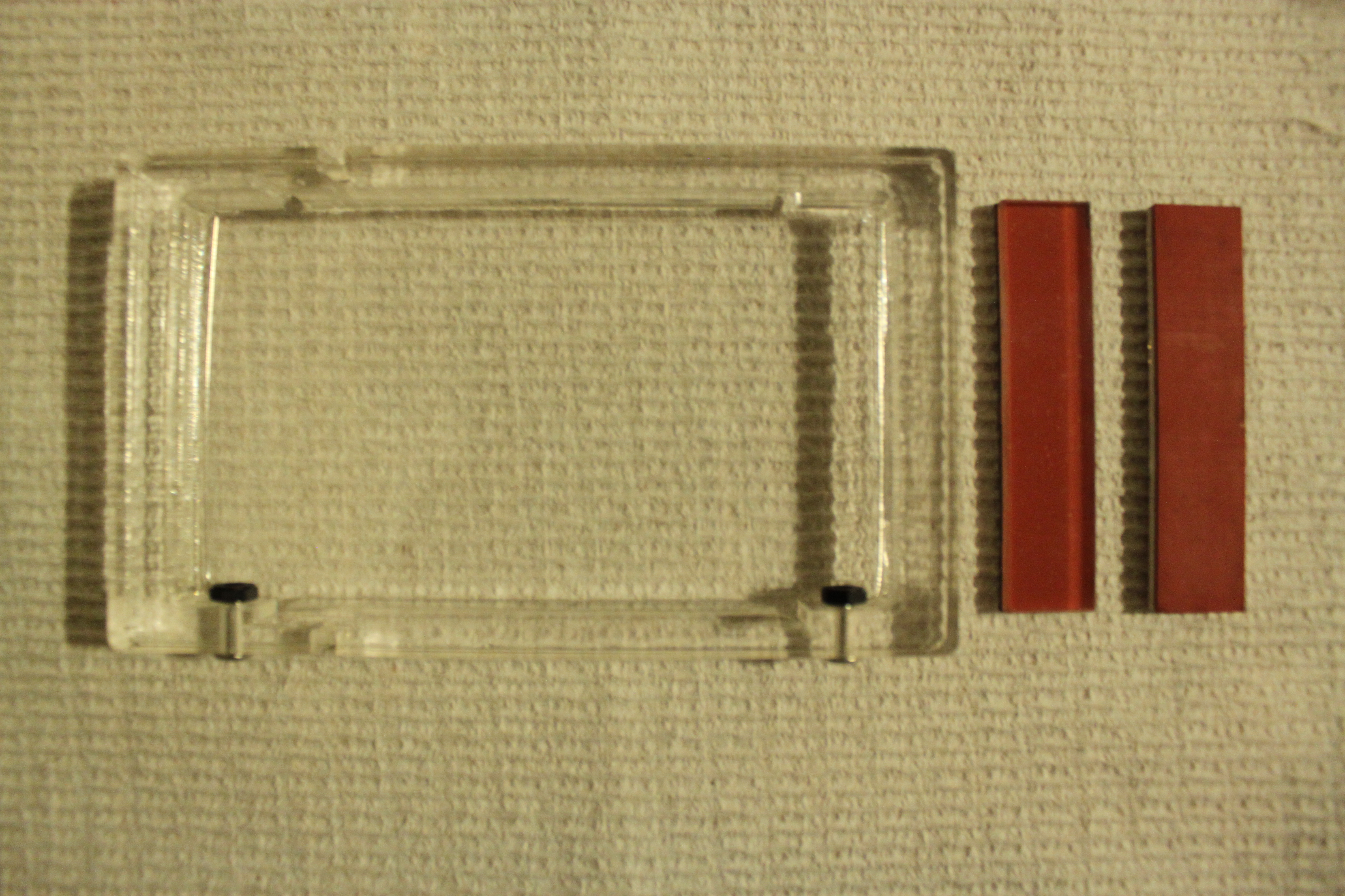
the box, and two dams for pouring the gel.
Here is the gel tray you see sliding out of the system on top. The electrodes are an incredibly tough alloy of stainless steel (316VLM. .016 diameter* Read my footnote on it). To the right are two dams for pouring the gel. One side is acrylic, and the other is somewhat soft silicone rubber with an adhesive backing. They are cut at as a laminate at the same time on the laser cutter to ensure that the parts are exactly the same size. I haven’t tested them, but I am optimistic, especially because of the laser taper, illustrated below.
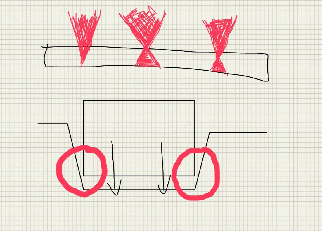
laser taper is caused by the beam spreading after focusing
This taper should help wedge the dam in. I would talk about the comb more, but I forgot the comb at the lab. It is pretty unremarkable. The image of the model below pretty much sums up how it works:
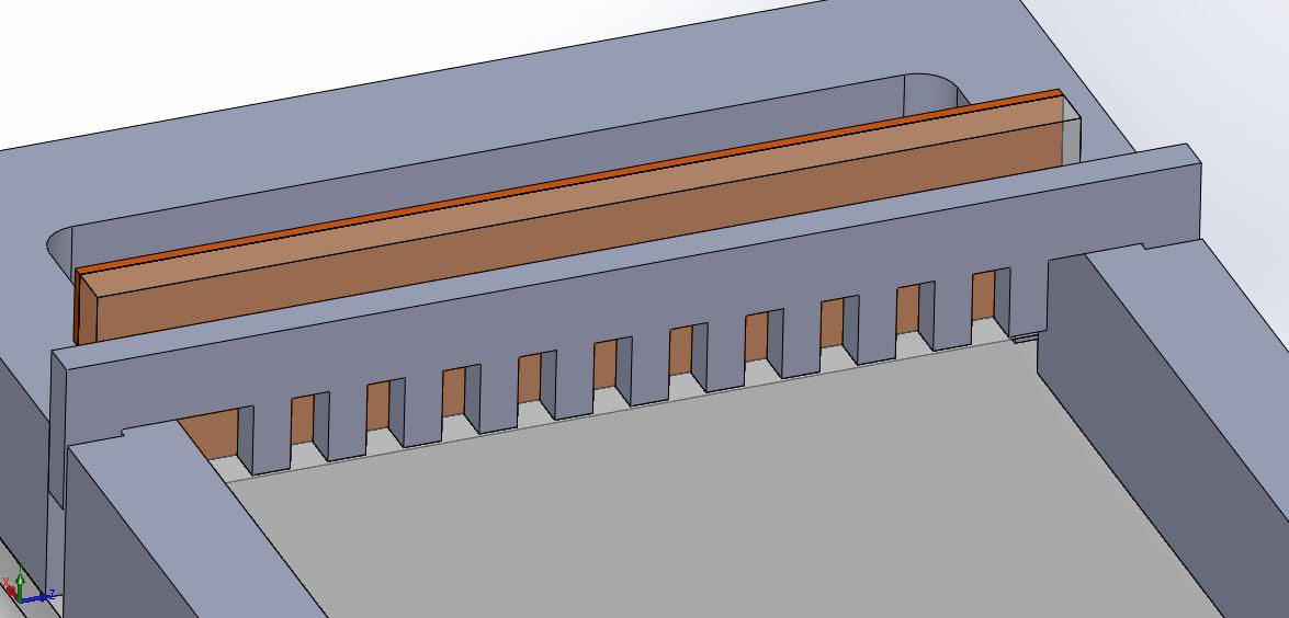
The least exciting part
I also finished the transluminator, which I think I will stick with for the kit. It is elegant in a lot of ways that I want to talk about, so it is getting its own post.
*You might be asking, stainless steel? Don’t we need PLATINUM electrodes? The answer appears to be no. Several people have had success with 314 stainless seizing wire (a boat/marine item), but according to aerospacemetals:
“Type 316 is known to be more resistant to atmospheric and chemical corrosion than any other grade of the stainless steels. Maximum corrosion resistance may be obtained by fully annealing this alloy. If the application calls for welding, Type 316L should be used as it is highly resistant to carbide precipitation and intergranular corrosion. Which usually occurs at high temperatures.”
Plus this wire is vacuum arc remelted, so it should be even tougher. I will have to do a proper stress test sometime.
