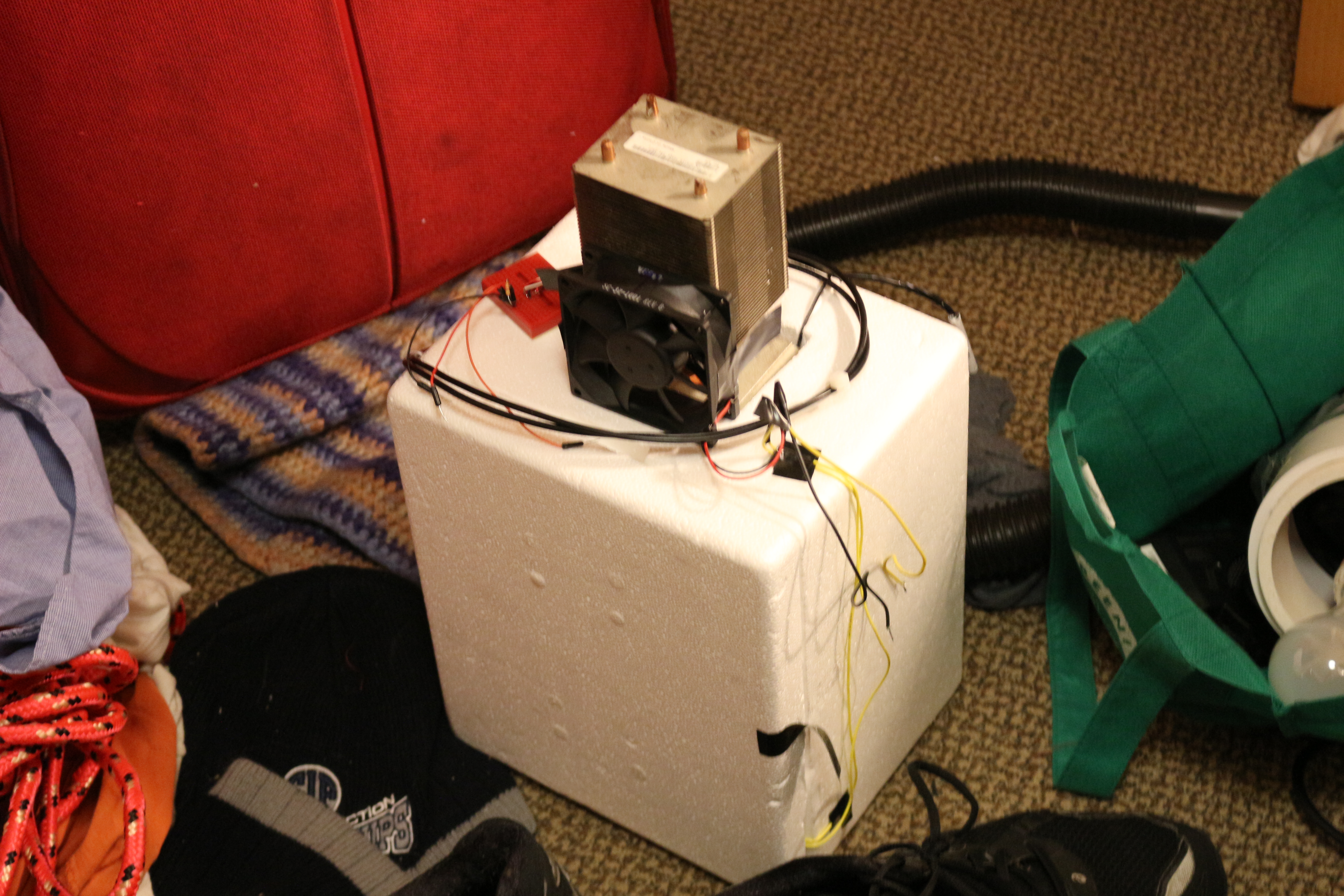
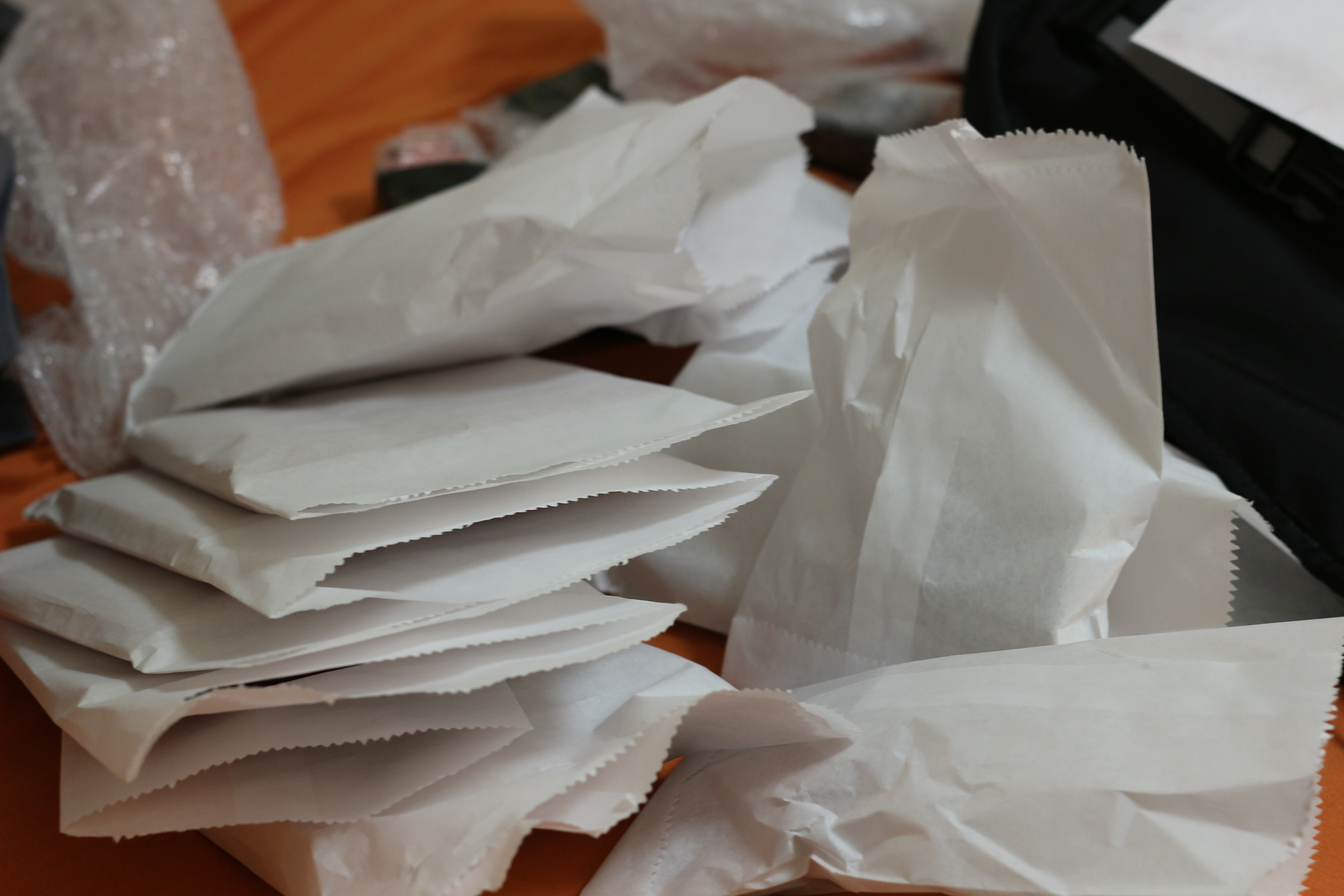
The incubator is hanging out on my floor
Incubators have bad UX
Springtime is here, and another ambitious biology project is in the air. I had a lot of fun redesigning the gel box experience, and so I am going to be doing a few more biology equipment projects. The first of which is an networked bacterial incubator.
However, is no mere incubator. This is an incubator re-imagined to be less horrible to use. Right now the steps to use an incubator are generally:
- Put plate of cells in incubator
- Hope that it is at the right temperature
- Check if colonies have grown yet
- Repeat until the colonies have grown, or overgrown
The problem here is that some poor soul (grad student) has to physically go to the incubator, and look at the plates and see if they are overgrown. If you think it will take 6 hours, and you put the cells in at 6 pm on Friday, that means you have to visit at midnight on Saturday morning, probably in a deserted building. Being in the lab alone is a bad idea. Rinse and repeat. That’s like going to the post office every hour or so to check if you got mail- it is a silly thing to do. Besides being silly, there are better things to do on Friday nights.
Redesigned Experience
The main things to fix in the incubator experience are:
- Having to go look at the cells at weird times
- Logging temperature data
- Logging growth data
The first point has been explained. The last two are to add security and debug features to the incubation process. This way you know if someone cranked up the heat, or left the door to the incubator open, and what the actual temperature is in case there is a problem.
Technical Solution
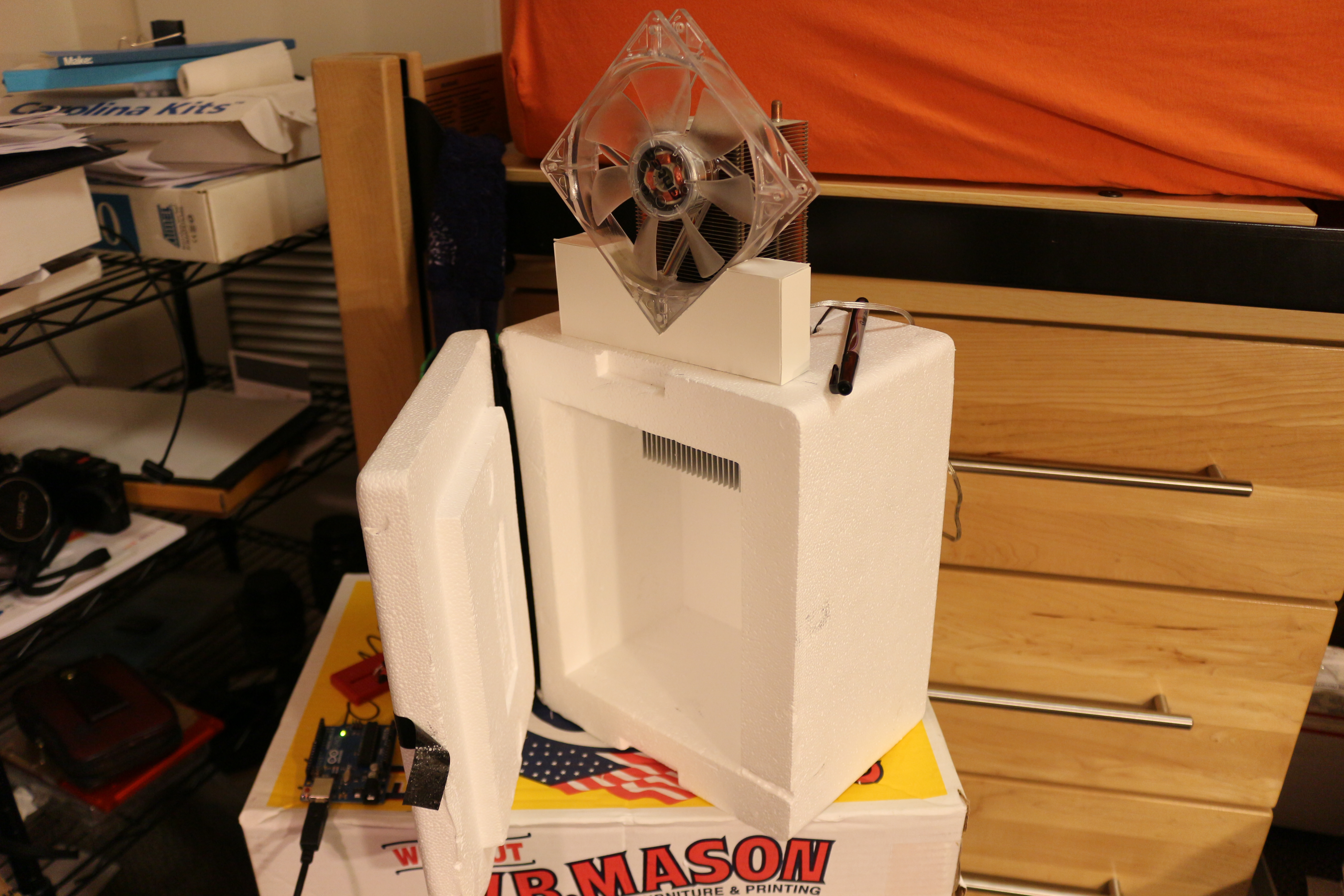
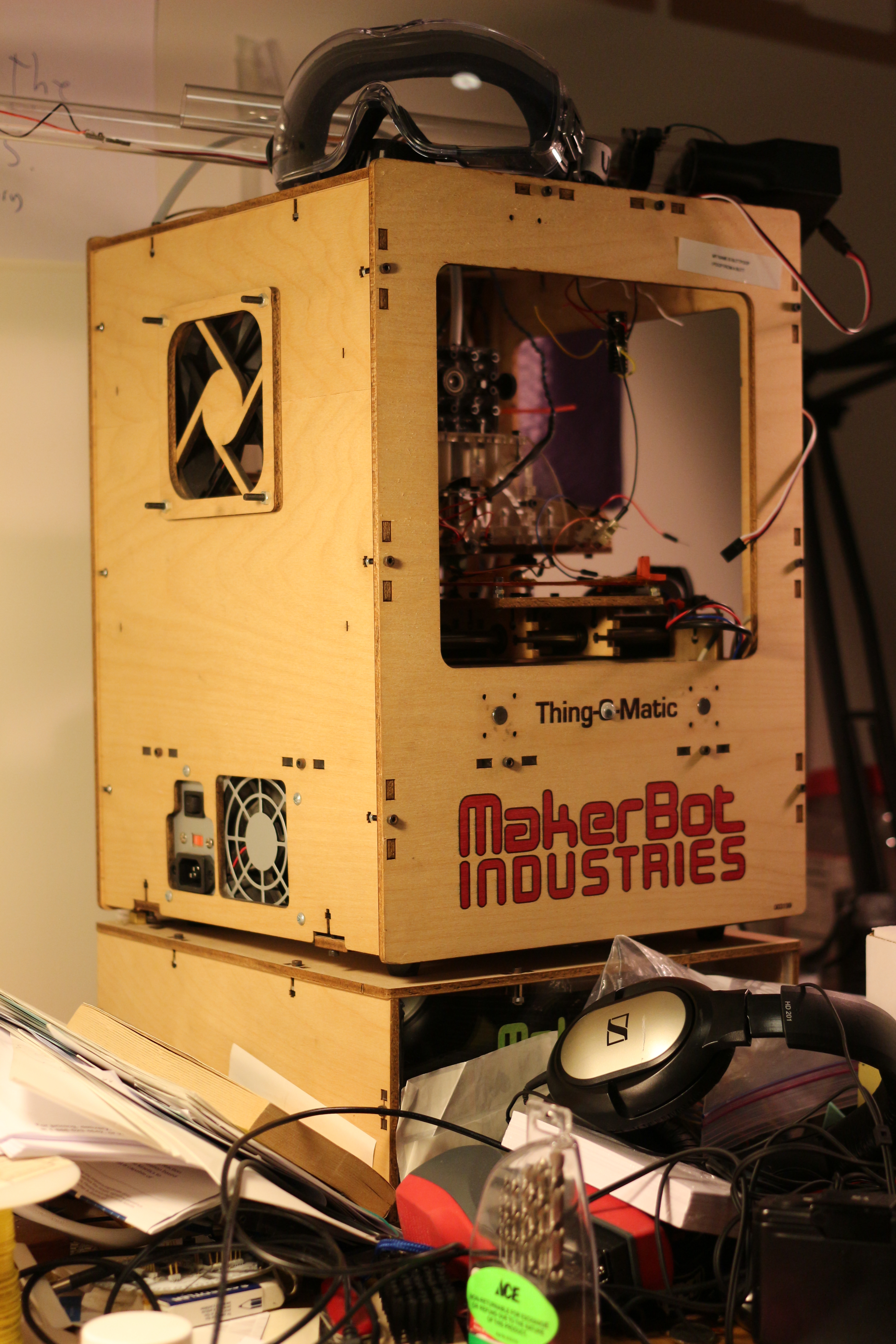
If you look at the incubator above, you will notice that it has a huge heat sink sticking out of the top. This is because this incubator can achieve sub-ambient temperatures down to about 2C, thanks to some peltier modules. This means you can have your cells happy and growing at full tilt at 37 C, and when you want to stop them, you can just turn the whole thing into a fridge. This means you don’t have to harvest the cells right away- but someone still has to make the call to flip the switch. To do this, they need a picture of the cells, and a button to press.
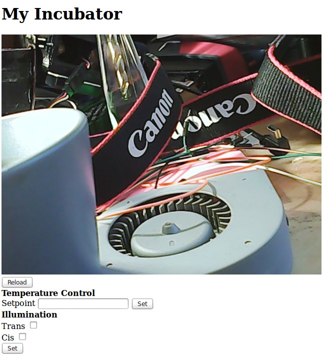
quick and dirty server with inputs for lighting and temperature. Pointed at my messy desk right now
The solution of course is to make the switch-flipping and picture-viewing happen remotely, via a webpage or an app. This is easier said than done, because of network security. As I understand it, if I wanted to host a website on my computer or any device connected to the wireless at school, I would have to go and ask IT to set up port forwarding from our public IP address to my computer. This would let the routers know that if someone is making an http request on port xxx, send the traffic to my computer. IT is not likely to approve this request.
Fortunately, if you have an internet connection it is easy to “dial out”- for example, you are reading this blog right now, which is on another computer. However, this website can’t just go around accessing files on your computer, which is a good thing for you!
The solution that seems to have taken hold is to have an intermediate platform hosted on remote server that talks to both devices. An example of this is the spark core cloud, which seems to be used to mediate data transmission to/from sparks and computers. I don’t like this because it adds an extra link and complexity in the connection between people and data.
The Progress So Far
-

-
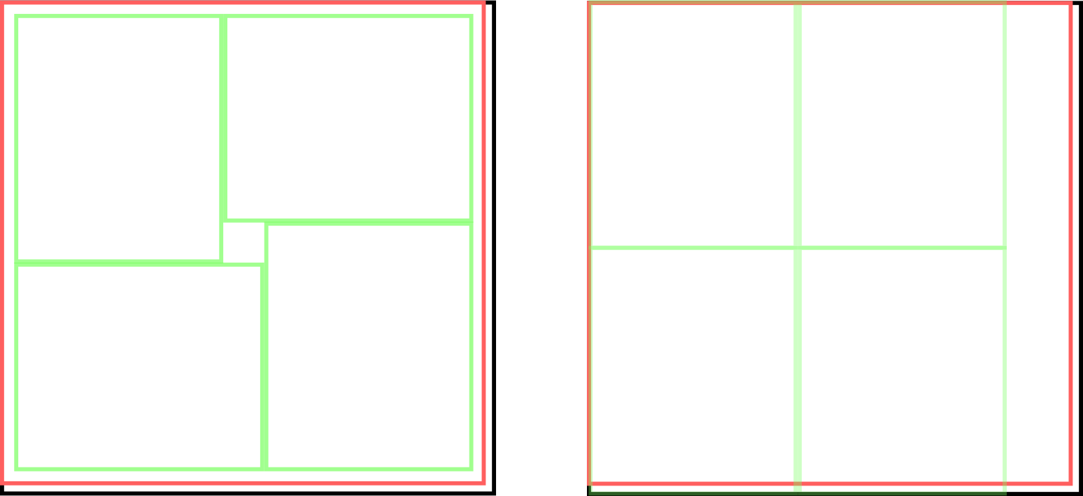
Cooling takes a lot longer than heating because heating gets an extra heating term from resistive heating
-

-
The incubator heating up and cooling down. Cooling during heating cycle is after the power was switched off.
Electrically and physically, the incubator works. This is more of an exercise in hacking together a connected device, so most of the hard parts for me are code and networking related. So far I have done a few things that I have never done before: write a server in flask-celery, template in jinja, and write an android app! I have to say they are probably not the finest shining examples of code, but it works.
The server will be deployed on a raspberry pi that will be connected to my LAN. The server has a page that has an up to date webcam image on it and button to refresh, and has an interface for getting data from html POST/GET to python code running on the server. There will also be an API for talking to it from other applications. The nice thing is that if I ever get control of my own router, I can set up port forwarding and it will be online for me to access anywhere.
One possibility is to have an android app for remotely monitoring the incubator. It would be nice to have it on your phone or tablet for when you are out and about. To this end I have tested an app that can post or get things from olins mobileproto twitter server.
I chose to use an http server and a pi, as opposed to maybe an arduino and a cc3000 because it gives me a little extra juice in the memory, power, and i/o departments. In particular, it has wired ethernet, USB support, and GPIO. This means it could be useful in other projects down the line. Normally I go with the barebones implementation but in this case the extra power can provide something like openCV, which could be useful to process the image, and I can use a nice webcam instead of a serial camera. Also, it can talk to other micros that might actually manage temperature control on a separate power bus. The pi is not a RTOS, so if it gets tied up or DDOSed or something, I really don’t want it to forget that the incubator needs to be switched off- therefore some kind of micro go-between is not a bad idea.