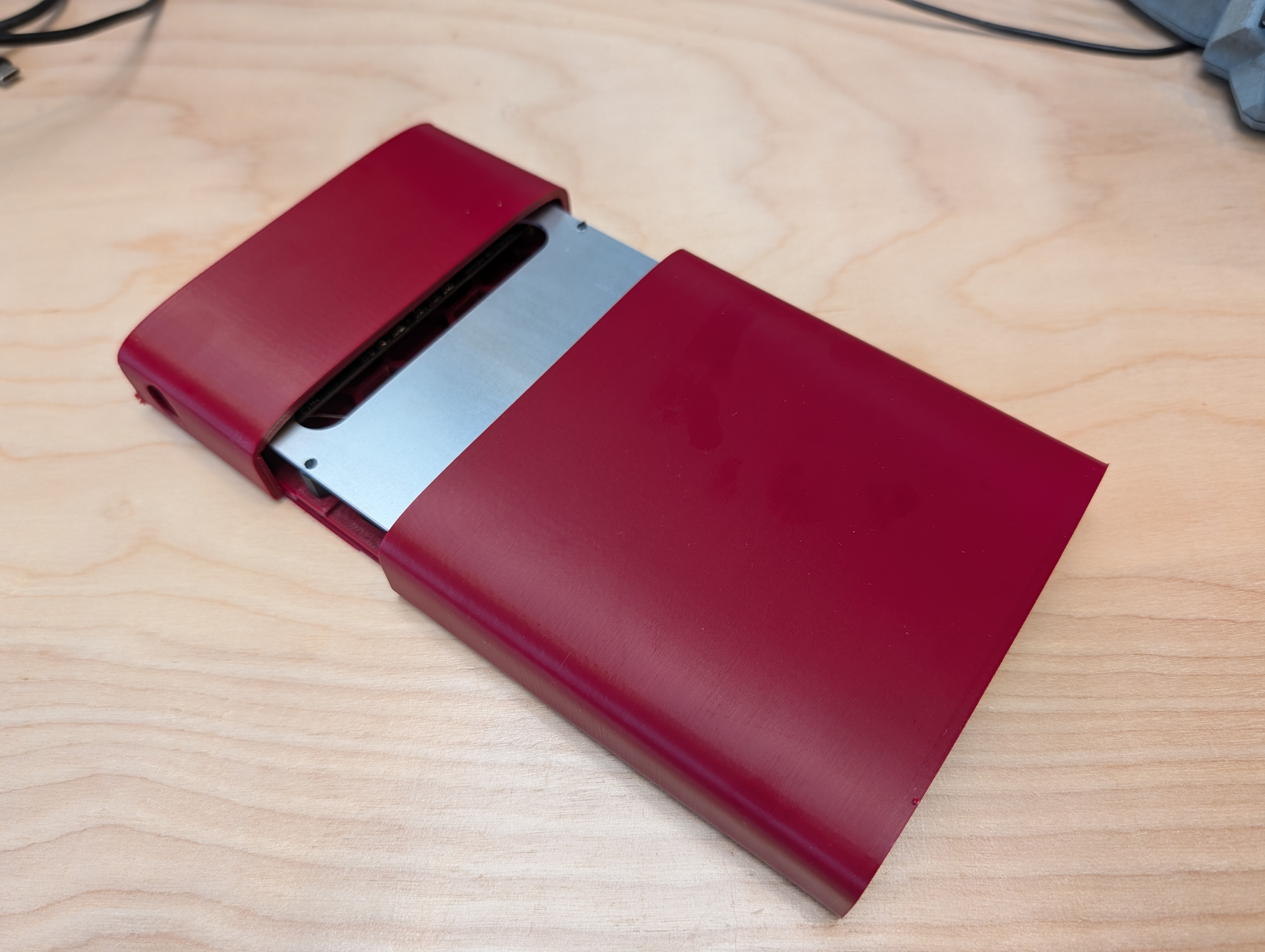
I’ve used my original PCB hot plate a lot. It is compact, heats up quickly, and most importantly is right sized for my application – big enough for almost any PCB I would work on, and low profile enough to fit under my microscope stand or to do assembly directly on. Its bigger than the MHP-50, and way smaller than something like the typical generic blue lab hotplate that people use for reflow.
It’s also much more sophisticated and powerful than the original PCB hotplate, in pretty much every way. I think the only vestiges of the old design are that it uses the same microcontroller and the same I2C pendant that I designed for the last version.
Handling More Power – 140W EPR
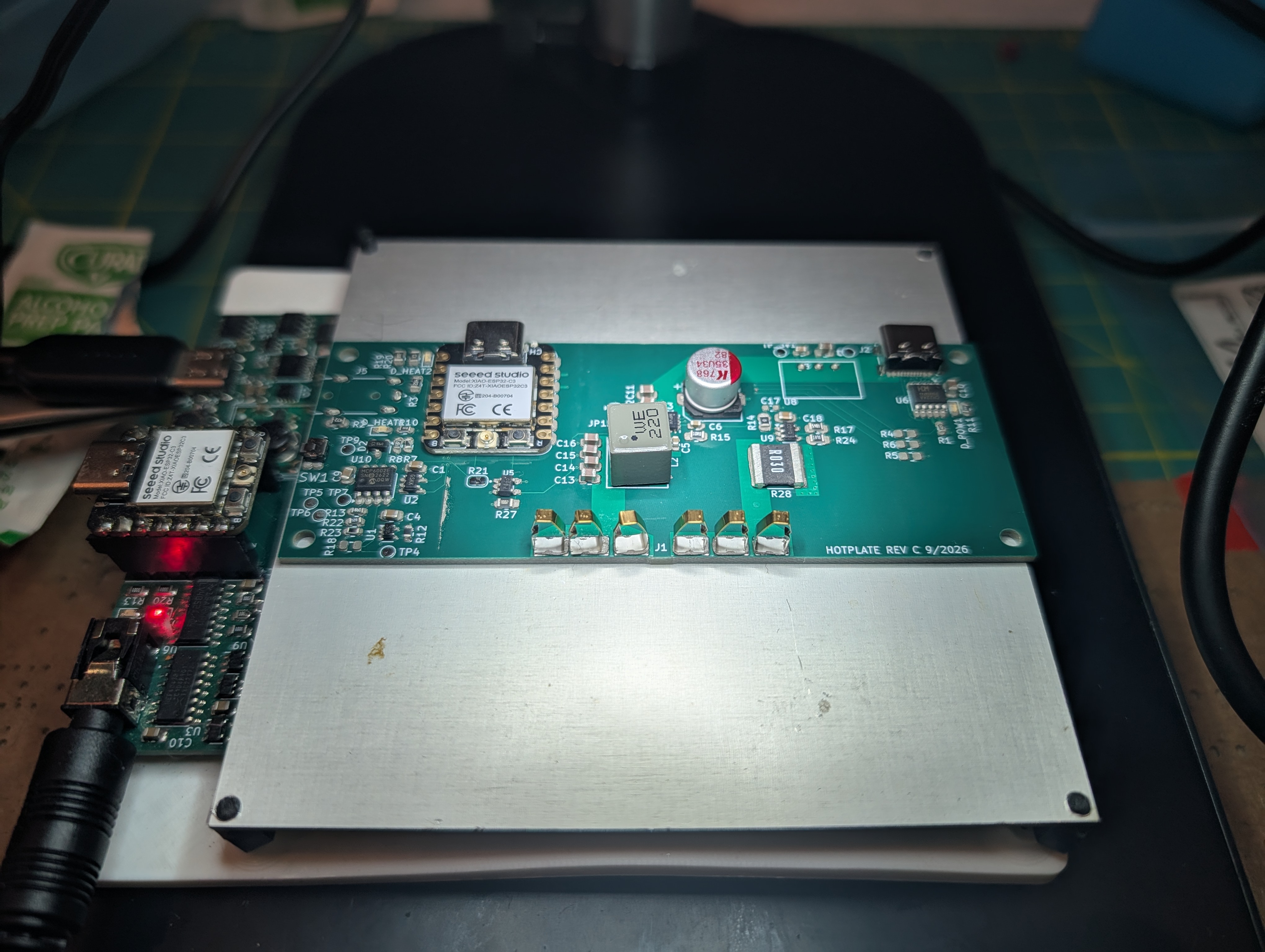
This plate uses a CH244A to ask for 140w EPR at 28V. The extra power is welcome, but its not straightforward to deploy. The original plate “just worked” by having a heater that would draw just over 5A at room temp, which was PWM’ed, and slightly less than 5A current at the hot temperature. The resistance started out low, and it grew proportionally less at high temperature and left more margin at high temperature. My first 140W heater design failed because I started out with a higher resistance value, to limit the low-temperature DC current. Once it grew by ~70% due to increased thermal resistance, it was impossible to deliver enough power to it to at high temperatures to keep it getting hotter. This design was self limiting.
In order to deliver maximum power at higher voltages, I needed a resistance that would be close to 5.6 ohms at ~200C. That’s pretty close to the original 3 ohm heater I designed, but with one catch – at 28V, the 3 ohm heater would draw almost 10 A instead of around 6A. This seemed like a less manageable inrush current to deal with than before.
Current Control
To prevent overcurrent from the power supply on the low resistance end of the heater design, I used a current-feedback buck converter. This is a typical buck converter, but the feedback pin is hooked up to a current shunt and non-inverting amplifier so that the feedback pin achieves its target voltage when the current output is high enough, not when the voltage is high enough. This type of converter will try to maintain a constant output current by servoing the output voltage until it hits the supply voltage. So for a 28v supply, it will try to deliver 5A until close to 28V.
This design is fairly optimal because at low heater resistances, 5A still delivers a lot of power. the heater power is P =I^2 R, so as R increases, and I^2 is held constant, the power actually increases with increasing heat – this is good because a hotter plate takes more heat to maintain, since heat creates more convection and higher rates of cooling. This also delivers enough power at low resistances to “kick start” the heater and increase the resistance.
The design is not truly optimal in terms of always delivering maximum power because the buck is not delivering 140W at the lower resistances- remember, the delivered power scales with R. A buck converter can trade voltage for current, so at the low resistance levels it could deliver more current, but in this case that is not necessary, and it would mean bigger magnetics and more expensive parts, as well as more control system complication.
One Temp Sensor to Rule Them All!!
One thing I didn’t like about the last design was that there were two independent temperature sensors on the heater – one for a dedicated overtemperature circuit, and one for regular temperature feedback. Both were NTCs, and its irritating to design a circuit for NTCs that detects both overtemperature and sensor loss (disconnection) conditions – it ends up needing multiple window detectors, and then those need to be properly combined and latched. And while having two sensors is perfectly safe, it seems like losing the measurement sensor and relying on the plate getting too hot before shutting down is silly – if any sensor is lost, it should turn off.
The NTCs also had a linearization problem, requiring a bank of resistors to make temperature measurements over the range I needed to measure. This also creates challenges around having a reliable overtemp limit, because the resistance changes very rapidly. Because of this it is hard to set a tight limit, because being off by “a little” either in the resistor bridge or trigger voltage creates a big swing on the overtemperature cutoff.
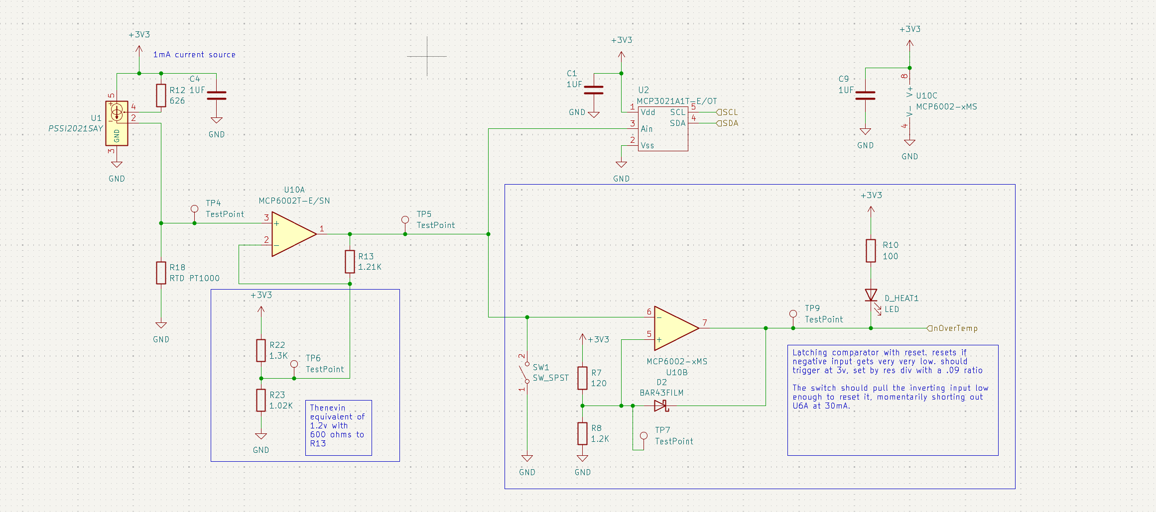
I finally realized my vision for an elegant temperature measurement and cutoff circuit with a RTD. There are three main elements to the circuit – a current source feeding the RTD (R18), a level shifting/range mapping circuit, and a latch.
Current Source
This is just a run of the mill application of a current source IC to drive the RTD. The source provides 1mA, and the voltage at TP4 ranges across 1 V to 1.9 V across 0-250C. This minute voltage swing is tackled in the next block, but the important thing is that if the sensor were to become disconnected, the voltage would land on the same side as an overvoltage- meaning that one side of the voltage limit (instead of two) can be set as the error state.
Range Mapping Circuit
The problem with the current source is that given my 10 bit ADC, the roughly .9v of voltage change across my 250C temperature swing only has about 300 ticks- that’s a little less than one C per tick. I wanted more resolution, so I used what I am calling a range mapping circuit to project the range [1.0, 1.9] onto [0.3, 3.0]. This gives me about 2.7x the resolution. This circuit is neat because it incorporates both a voltage subtraction and a subsequent gain. I chose the output range to avoid being near 0 to avoid any weird behavior near the op amp rail, and I left .3v on either side to avoid any poor ADC performance near the extremes of the range, although I wouldn’t expect much trouble with this particular ADC, unlike the original ESP32 ADC that it replaces (which is bad at the extremes).
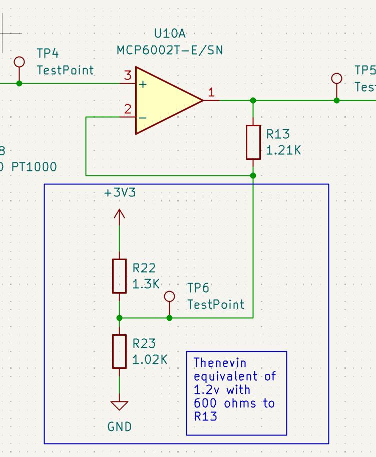
The circuit is explained in great detail here, but its worth having a quick explanation here. Basically:
This is solved by solving a system of equations at the operating points, it is convenient to use the high/low input/output range for this.
Latching Circuit
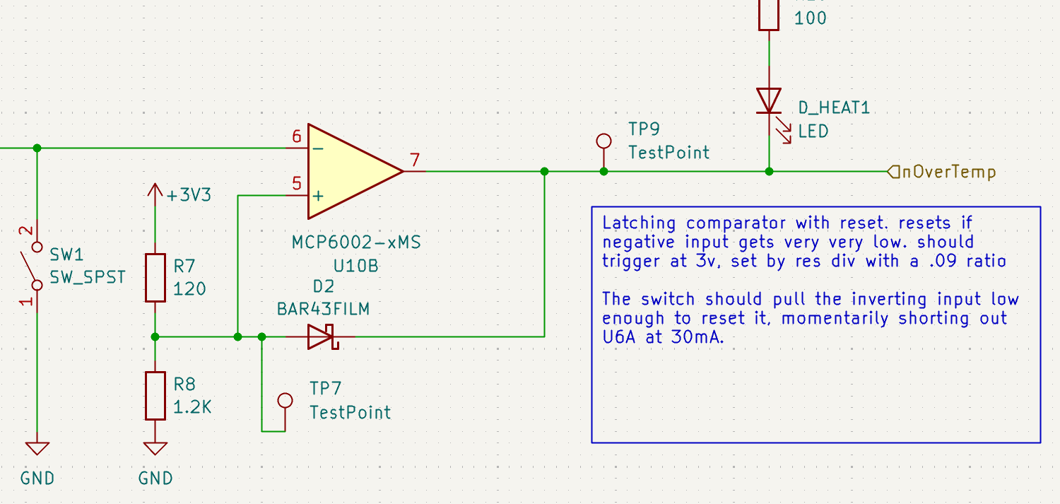
Once the overtemperature voltage at the inverting input reaches the limit set by R7 and R8 (about 3v), the output snaps low. This lets D2 conduct, and the non inverting input reaches about .3-.4v or whatever the diode Vf is. This keeps the circuit locked out, until the output voltage of the sensor gets very low (near 0 C), or until SW1 is pressed. This signal, nOverTemp is anded later with the power control signal to block it in case of an overtemp event.
Case Details: Snap fits + Expansion Joints + Mechanical Details
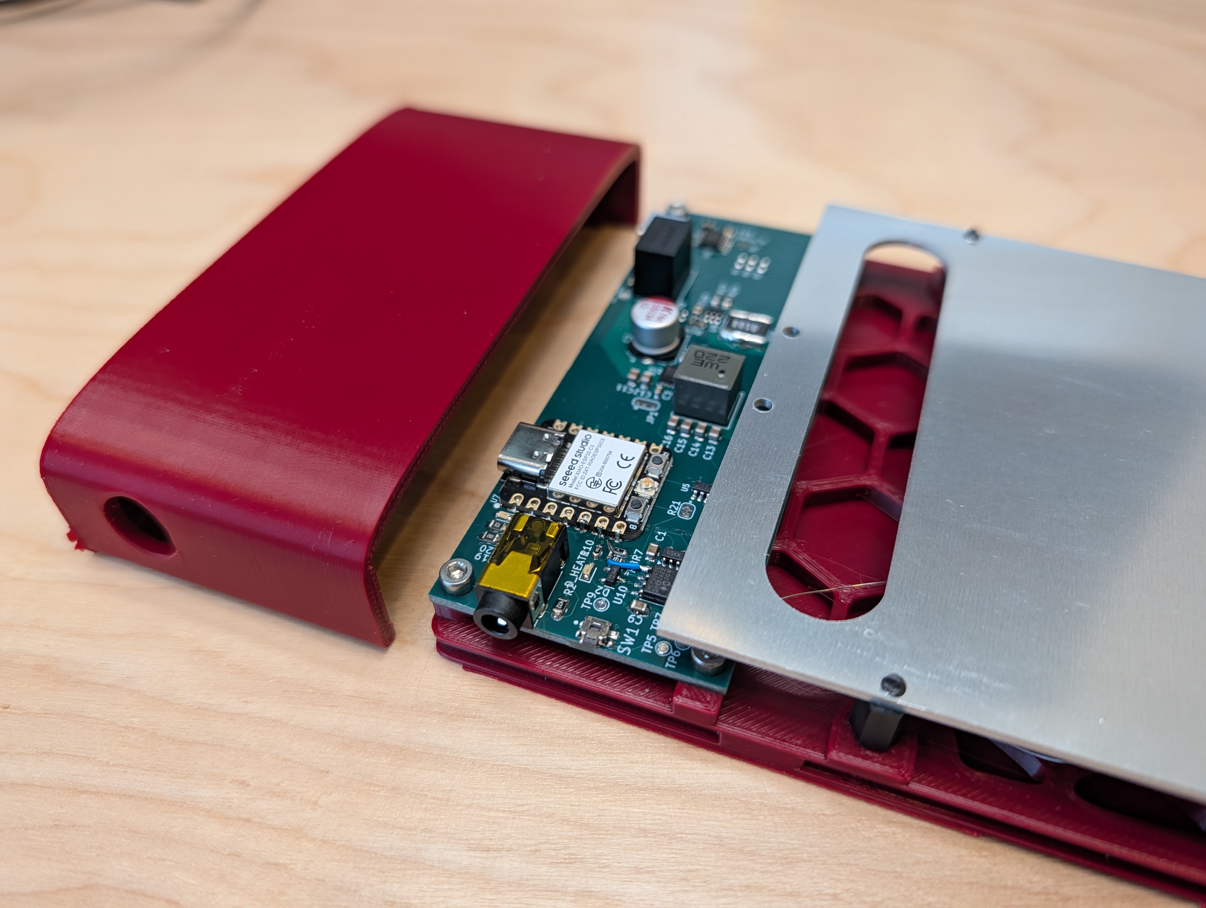
In addition to all the other improvements, I also focused a lot more on the construction of a case for this project. The last hotplate had a lot of issues with warping, softening, and generally tearing itself apart with differential thermal expansion. I am hoping that printing this in ABS will prevent the baseplate from softening too much, and causing warping. So far so good!
Overall case Joining Strategy
3d printing a box can be more challenging than you would think, once all he requirements are added up. In this case, I needed a very low profile case that when “open” kept the heater element low on the desk and that was “tight” to the heater profile. This helps to prevent parts from being dropped and lost under it, and it lets you get your hands right up to the plate when doing assembly on the plate itself. The case also needs exits on two sides for protruding connectors, and a sliding lid for the heater area.
One case style I’ve used before, and that seemed promising in terms of a sliding lid, was a case that slides together, meeting in the middle, perpendicular to the PCB. However, last time I did that, only the front and rear had connectors/stuff that stuck out, and I had none of the thickness constraints.
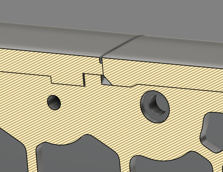
What really helped to keep this feasible was a dovetail along the length of the case. In the back, permeant half of the case the sliding lid dovetail ends in a square slot with a square snap. Its only ~1mm deep, so it can be snapped back off with some bending of the lid, but that wont happen by accident since it requires a lot of asymmetrical force – something that wont happen if you pick the case up. In fact, pinching the rear of the case holds these snaps in even more.
The front lid is also held in by a similar dovetail and snap, but the front snap has a ramp on both sides of the snap and in the groove. This makes it easier to print, since there is no sharp overhang, and it makes it easy to slide the case lid on and off, while retaining the lid.
You can also see some other details in this cross section – namely the reveal around where the case parts come together, and some relief/clearance in the back snap joint. The front snap joint has less clearance because the tapers will fit even if they don’t totally bottom out, and I wanted the joints to remove all play- but the rear joint needs the square snap fully seated in the hole, or it will bow the whole case out.
Flush Mount Heater and Expansion Joints
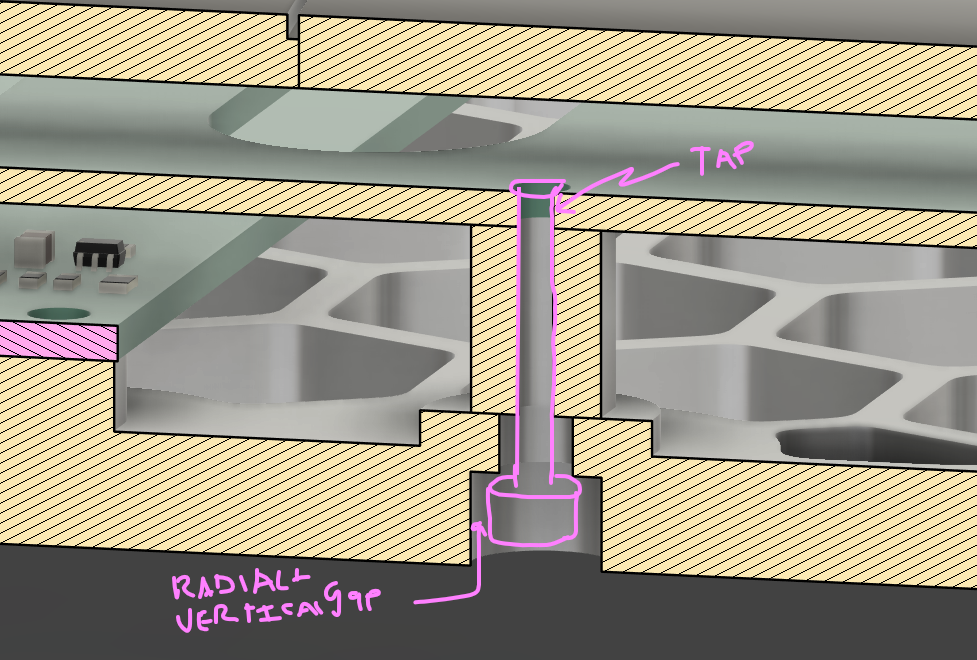
One detail to notice here is that the mounting to the baseplate is done flush to the surface of the plate- there are no screw heads to bump into. This was achieved by tapping the aluminum PCB and then screwing it to the screw through the bottom, through the standoff, and into the PCB itself, and then cutting off the nylon screw head flush with the plate. Putting the screw all the way though the threaded standoff creates a lot of friction. This lets me leave the screw head fairly loose in the counterbore, while still keeping the whole assembly captured to the plate.
This loose screw serves as an expansion joint, allowing some “float” of the heater element when it (or the baseplate) expands. Hopefully under constraining the system will prevent stress on the plastic when hot, avoiding creep/plastic deformation. I am not sure if just the heat or heat and expansion killed my last plate, but it will be interesting to see how this one holds up and if this part actually needs to be metal.
Magnetic Feet
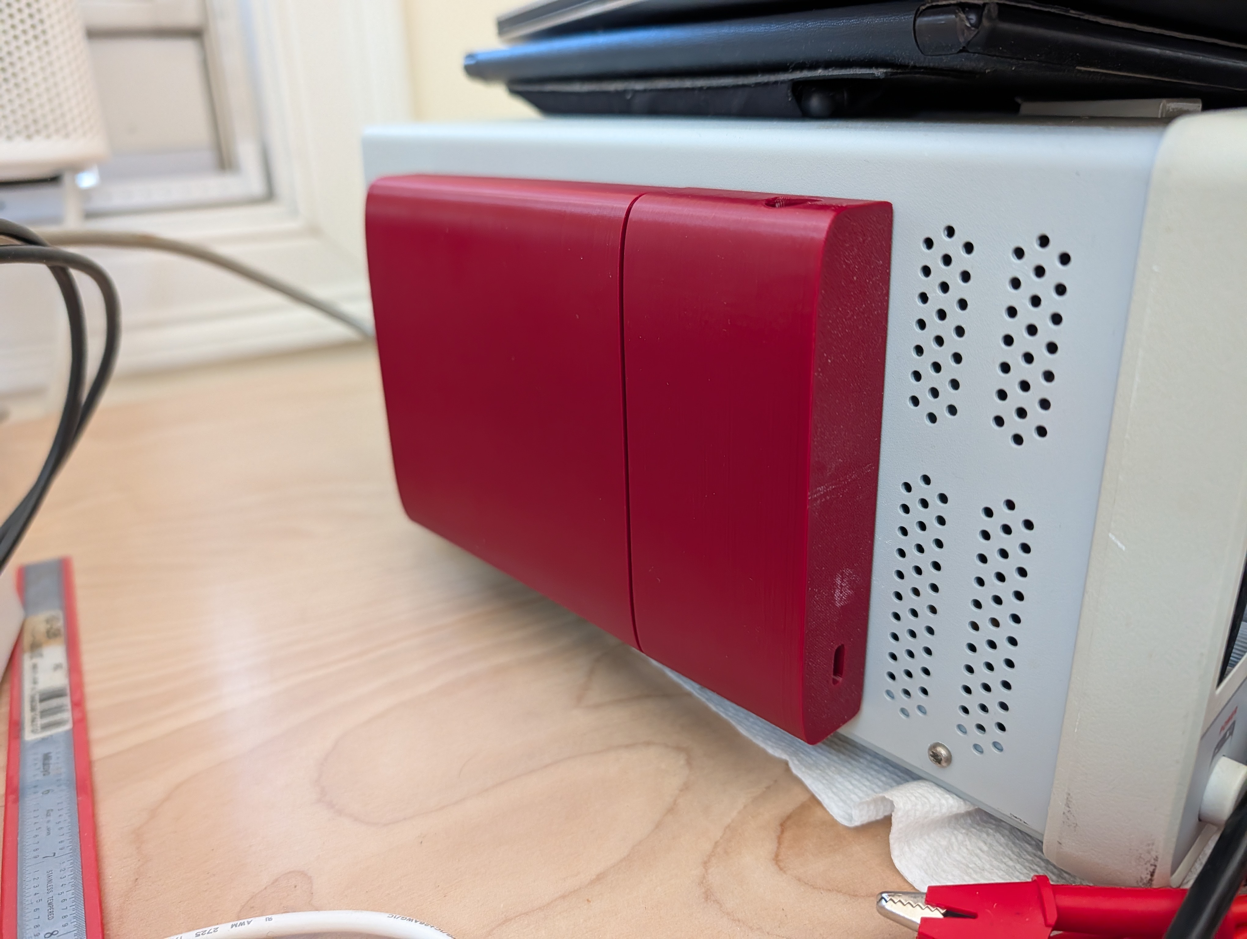
Finally, the case has a cover and a flat bottom, to keep the electronics safe and to allow for vertical storage on the bench. As a “nice touch” The base also has magnets in it, so it could be hung up on a metal tool board or for extra grip on a steel plate like the one under my microscope- this should help prevent it from being knocked around, and should keep it handy for assembly tasks.

