After listening to my Make Your Own Gnome, I decided I wanted to make my own led lamp. Specifically, I want a lamp that:
-is dimmable from “nightlight” to “worklight”
-is color-temperature adjustable from warm to cool light
-has some kind of smarts- daytime color temperature tracking, live outdoor color temperature matching, remote control
LED Choice
I decided the “hybrid” LED strips from waveform would be nice based on having a high CRI, and having a mix of warm and cool LEDS on separate channels. These LEDS strip lights are “DC constant voltage” strips meaning that you put 24 volts across the power/ground of each to light them. Each color temperature has a separate ground, for low side switching. Each rail (one per color temperature) has in parallel several sets of 6 LEDs in series, with current limiting resistors. The number of LED units in parallel is controlled by the length of the strip, with 6 LEDs per color per 4″.

Since I want to have worklight-bright intensity from either a warm or cool color, I need about twice as many feet of LEDs than I would with only one brightness. Empirically, this is about 4.5 feet of LED strip (per color), or about 2000 lumens, or a total of 9 feet and 4000 lm combined.
System Architecture

I decided to have a main control board and several strip driver boards. Each control board has switching supplies for 3v3 and 12V, and an ESP32-C3. The control board has enough connectors for three channels of output consisting of warm white PWM, cool white PWM, and driver enable, as well as a connector to distribute 12V. 12V is used to run the FET gate drivers.
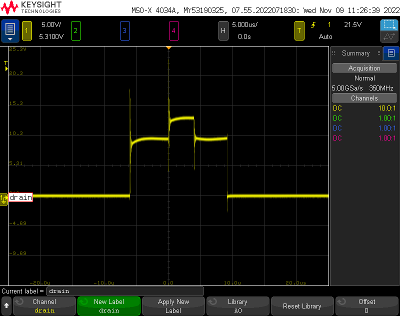
At higher currents (single- digit amps), the inductance of the wires from the power supply (30 cm or so) and the switching can start to cause some ground bounce, so having local decoupling is needed- and reducing the overall strip length also reduces the total inductance per-strip. Above is the drain of the fet switching the warm channel- as you can see switching what is essentially two inductive loads causes some voltage spikes, which fortunately do not exceed the VDS of the FET.
This modular architecture also lends itself to reuse for a two or one strip lamp.
Switcher Board Detail

A FET driver is way better than driving the FETs directly from the microcontroller, because it drives the gates at a high current, higher voltage, and without the inductance of long wires coming from the controller board (which could be several feet away). It also reduces the requirements for the FETS, because they do not need to have low RDSon at logic level drives.
Driving the FETs fast is important, because the longer switching takes, the longer the LEDS will be operating with additional current limiting, and therefore far from the target current. This change in current can cause the leds to shift their output spectra, which defeats the purpose of having really nice high CRI LEDs. Additionally, the longer switching time can lead to frequency limitations e.g. if the switching time starts taking up most of (or exceeding) the period.
I want to switch at 25kHz- this is above the audio threshold, so any components vibrating due to switching (capacitors) won’t be audible. This is also well above what a person should be able to notice for flicker (120 Hz) and it seems like its also well above the frequency where it would affect a phone camera with a rolling shutter. 25 kHz means that the period is 40uS. I estimated that I want at least 10-100% duty cycle, so a minimum on or off time of .4uS. I estimated that the total switching time should be no more than 10% of this minimum time, which gave a rise/fall time of 200nS.
The FET has a gate charge of about 9nC, and the driver can source on the order of 1A, so the switching time should be a on the order of 10 nS- well under the 200nS limit. This means that the minimum on time, allowing for 10% of the waveform to be rise/fall time, is 200nS. This would allow dimming to .5% full brightness, which is very dim indeed.

As you can see here, the real rise time is pretty much the predicted 10ns, with a symmetrical falling time, so the driver should be suitable for this application.
Concluding Thoughts

The switching board works fine, and I’ll certainly use them. The light is GREAT and being able to control the color output is awesome! Of course, in the process of this design I have come up with some improvements for a next iteration.
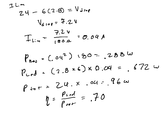
First of all, the efficiency of these lighting strips is Not Great. Per-color channel per-section (4″) they consume almost a watt (.96 W). The problem is that the LEDs consume only 70% of that energy, and they are not 100% efficient. 30% of the energy is burned off as heat in the resistors, which are wisely distributed along the strip. While this is much better than an incandescent bulb, it makes the strips get pretty warm, with the outer aluminum shell reaching about 40C in 20C ambient temperatures.
The reason for this voltage design decision seems to be wanting to run the strip off a higher voltage to reduce IR drop along the length of the strip, and 24V being a ubiquitous supply voltage. Since my strips are relatively short for this type of application, IR drop is not a huge issue. Given 6 LEDs in series, dropping down to even 20V would result in an improvement to about 85% efficiency.
Going a step further, a current-controlled switching supply could be used per-section of LEDS. While this is more expensive, I expect it to be much more efficient (close to 90/95%). Given that I’m not sensitive to a small increase in BOM cost, this could be just fine.
Second, I found the WAGO connectors to be annoying to hand solder, and a bit expensive. They are really nice, but ultimately I don’t think they are worth it. Standard screw-terminal headers would be just fine.
Next up: building the lamp+controller.
