Hopefully my catchy title helps people find this post. After spending some time building a tools to compare A/D converters, I wanted to share some results from popular micros and previously popular (but now out of stock) ADCs.
Single Reading Accuracy/ENOB
ENOB, effective resolution, noise free resolution – these are all ways people describe an adc. I’ll provide the ENOB based on IEEE 1057, which is described as:
ENOB = log2 [full-scale input voltage range/(ADC RMS noise × √12)]
I will also list how good a typical measurement is from 5-95% of full scale. This comes from the average standard deviation across all codes. In theory, this is equal to the ADC RMS noise. I like this number because it tells me the typical LSBs of noise from the converter. However, because I didn’t test per-code the type of distribution, it does not necessarily mean that the noise distribution is gaussian.
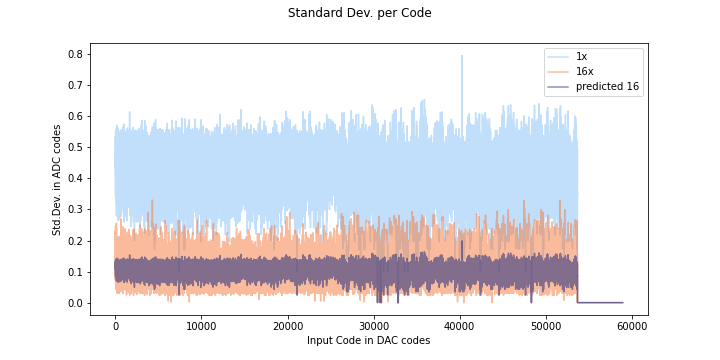
If the noise distribution does not behave in a gaussian way, the predicted oversampling will not be accurate, as you can see here. The orange is data oversampled at 16x, and the dark purple color is the predicted standard deviation.

Here is a histogram for a random DAC input code from the ADS1015. As you can see most of the codes are code 400, so oversampling wont help much- the average will not improve much because most of the time code 400 will be returned.
Compare this to the SAMD standard deviation plot:

Here the predicted and actual 16x measurements start to line up pretty well round code 40000. If we look at code 42000:

The distribution looks a lot more gaussian, and covers many codes- in this case averaging can help, and the predicted error lies up nicely with the measured error.
| ADC Name | ENOB | STD.DEV. (LSB) | STD.DEV. (Ideal volts) |
|---|---|---|---|
| ADS1015 | 10.6 | 0.39 | .00019 |
| ESP32 | 6.2 | 16 | .00429 |
| SAMD21 | 8.2 | 4 | .00097 |
| SAMD21 16x | 10.4 | .89 | .00021 |
| Atmega328p | 9.7 | 0.36 | .00038 |
Unsurprisingly, the ADS1015 is the best in terms of ENOB. Since the ADS is actually an 11 bit ADC (it reserves a bit for the sign, but it never uses it in single ended mode). It costs as much as any of the other chips, but it has only one job: being an ADC. The ESP32 really is pretty bad, as it loses about half its effective bits to noise for a given reading. The atmega comes in at a respectable 9.7 bits! The resolution is lower than the ADS, but much better than the ESP.
The SAMD21 ADC is what I would like to use. looking at the standard deviation chart, it looks like 16x oversampling is reasonable to do. This would give similar performance to the ADS1015 in terms of noise.
DNL/INL

The ideal code width for an ADC is 1, and the DNL is the error from the code. If we have consistent code sizes, it will be easy to compensate for, but codes that represent an extra-wide or extra narrow voltage range are more difficult to compensate for. If the DNL is -1, the code will be missing (the narrowest width a code can be is 0). Missing codes are very bad, because its hard to tell if they are missing or just really really narrow. If you map the adc and compensate by ignoring that code, there will be an LSB of offset when it reappears.
The most interesting stats here are the average code (this better be about 1) width and the standard deviation. If code widths are all about the same (even if they are say, 1.2 on average), it’s good, because each step is a predictable size. If the widths are all different, its hard to tell how much the measured voltage changed with 1 LSB difference.

I flagged any codes that were larger than 2 standard deviations from the mean. For most ADCs this only catches high (wider) codes since if the standard deviation is >.3 LSB, 3 standard deviations below the mean is a missing code (DNL = -1).
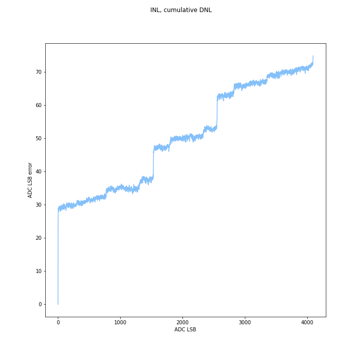
INL was calculated as the sum of the DNL. Max INL is the maximum error you expect to see from a straight line. Positive and negative DNL cancel out, but very high DNL mid-range is hard to compensate for because you need a lot of small negative codes to get rid of it- and while positive DNL can go to any number, INL can only go to -1 before the code disappears.
High DNL at the start or end can be compensated for- basically, you just add a DC offset and dont use those codes. If the LSB error is consistent, or if steps are mostly slightly wide/short you get a gain error, which can also be compensated. However in the middle, it is hard to compensate for because there is a big jump. In theory you can just note that measuring a specific code maps to a wide range of voltages, but that makes the ADC kind of nonlinear and bad, plus you need a huge lookup table.
I took measurements with and without the gain/dc offsets applied on the ESP32 and SAMD21 ADCs. Both these micros have built-in compensation values. I also manually compensated the Arduino ADC for fun.
For Worst DNL, I only included values from 5-95% of the range, even for uncompensated ADCs. I feel those numbers are a better metric for how good an adc is mid-range. If no wide codes were reported, I gave the highest code width measured between 5-95% of the range.
| ADC Name | Average Width ± std dev (LSB) | Worst DNL (LSB) | Wide Codes (#) | Max INL (LSB) | Max INL (volts) | Missing Codes (#) |
|---|---|---|---|---|---|---|
| ADS1015 | 1.00±.09 | 1.37 | 6 | .16 | .00008 | 0 |
| ESP32 | 0.91±2.06 | 4.47 | 0* | 153.03 | .041 | 14 |
| SAMD21 | 1.01±.61 | 3.9 | 46 | 74.75 | .018 | 0 |
| ATMEGA328p | 1.08±.19 | 1.36 | 0 | 84.48 | .090 | 0 |
As you can see, the ESP32 ADC really is terrible (as promised by the datasheet). The standard deviation, DNL, and INL are all high, and there are missing codes! On the other hand, the dedicated ADS1015 is really good. The thing that surprised me here is how bad the SAMD21 is in terms of worst case DNL. It does not add up quite as high as the ESP, but its still not great, especially with all the wide codes that it has mid-range.

(Un?)surprisingly the Arduino ADC did well in overall INL, even uncompensated, compared to the ESP32. This is pretty cool, since a lot of people use it. The INL error chart shows it should be pretty easy to compensate. this is a “good” plot because it shows that on average the code width is a little wider than it should be, since INL increases in an apparently linear and monotonic fashion, with some offset near 0.
Compensation:
I will look at this in my next post, using the collected data. Aside from oversampling, the next adc-error correction technique is to change the assumption that 1 LSB = 1/2^n volts. If we have measured all the code widths as 1.1 LSB (in volts), then every code we are (on average) adding .1 LSB INL! This causes gain error in the ADC.
By assuming that each adc code is on average wider/thinner than 1 LSB, we can correct this gain error. The tradeoff is a change in range and in resolution- if the resolution goes up ( average LSB<1) the range will go down- we wont have enough bits to measure the whole range. if resolution goes down ( average LSB >1) the resolution will go down but the range should go up (although it may not, because ADCs are poorly behaved at high and low values).

Thanks – interesting results on various ADCs. Would you like to perform some similar tests on the Pico2/RP2350, as it had some interesting DNL ‘holes’ as we are discussing on the R Pi forum.
hey tony, I think that would be very interesting. Can you send me link to your post?
https://forums.raspberrypi.com/viewtopic.php?t=376614