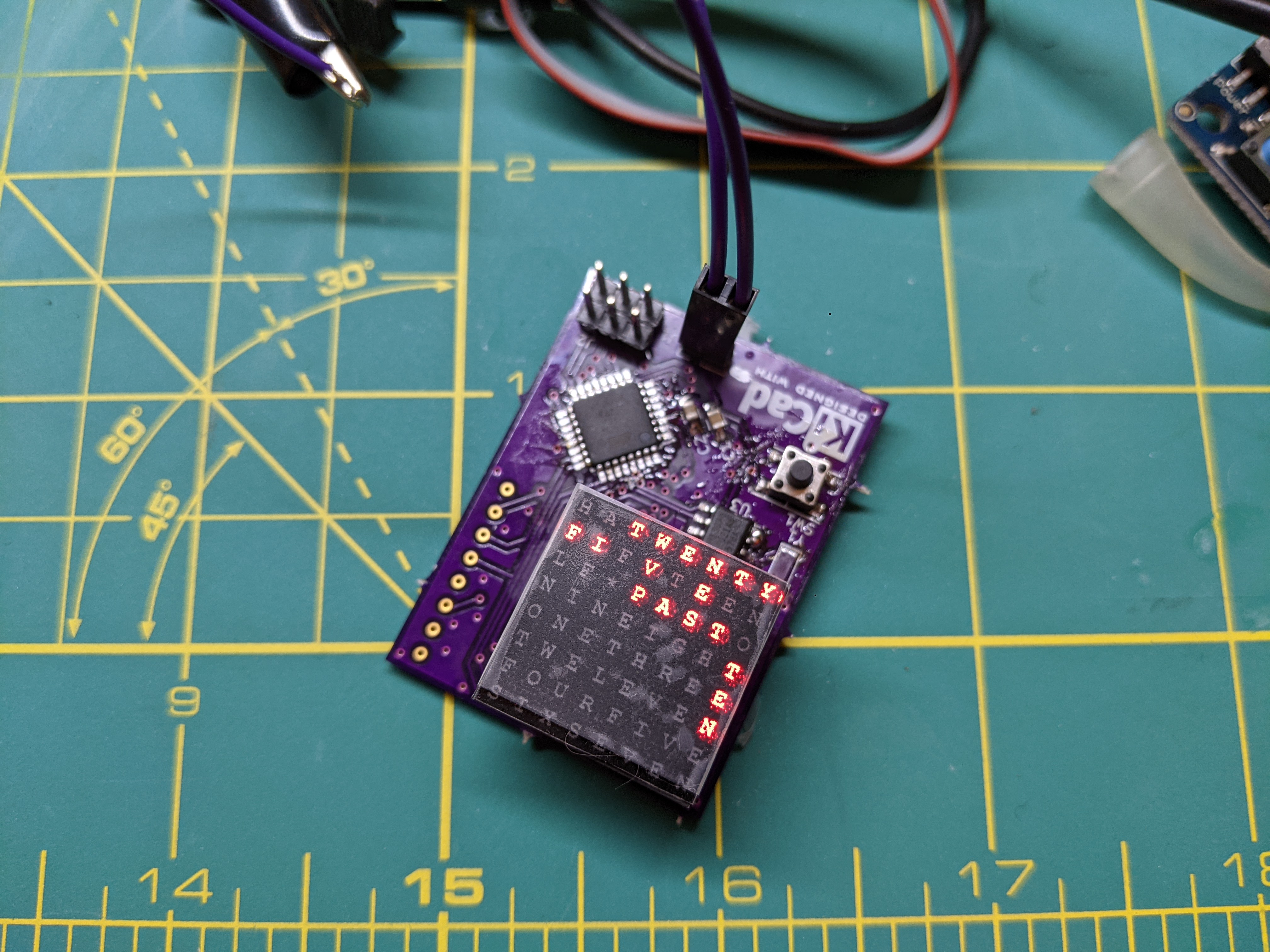
I am planning on teaching some people to use kicad, since its my new favorite EDA tool. I searched high and low for a decent circuit that would do something cool, with a good variety (but small number) of parts. Basically something fun and not intimidating. I got hooked on formatc1702’s micro word clock. It is an excellent use of the atmega8 series unusually high current drive outputs.
Challenges
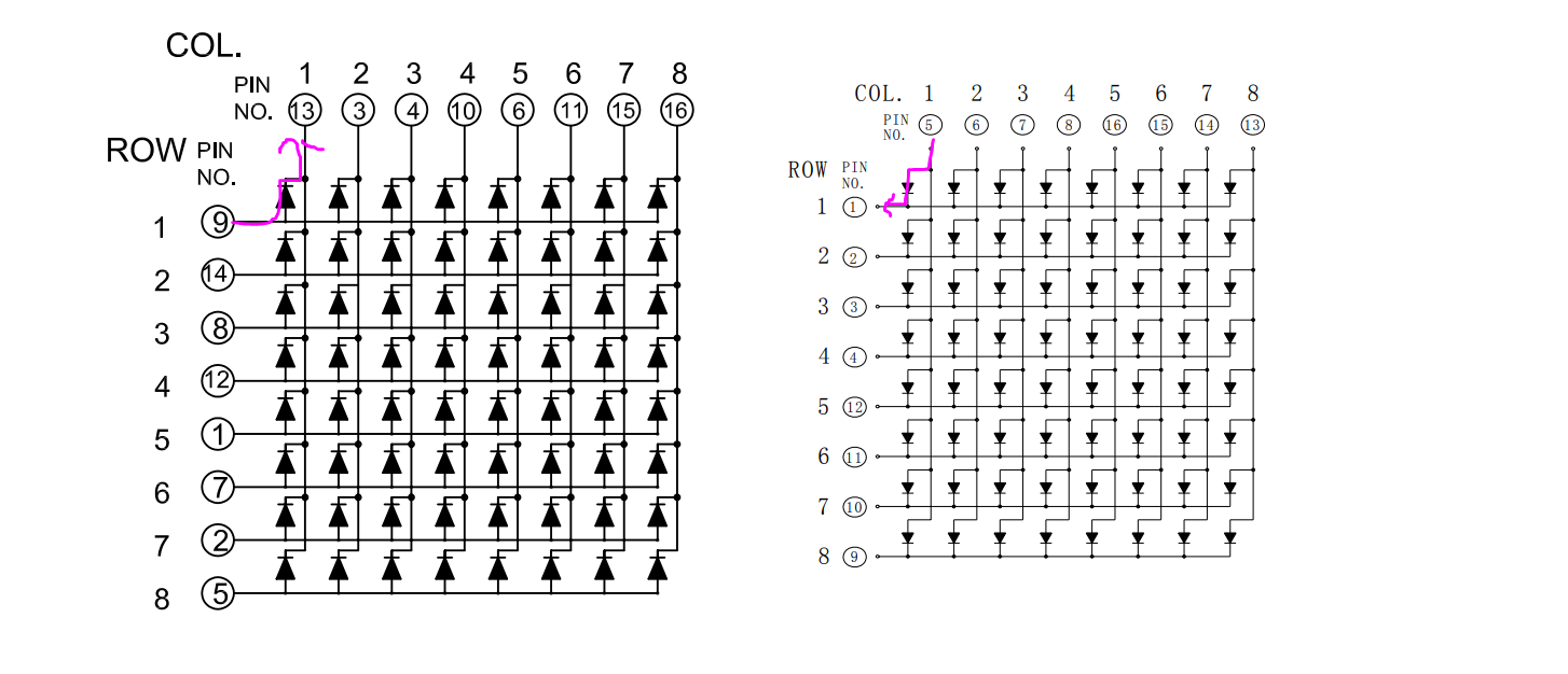
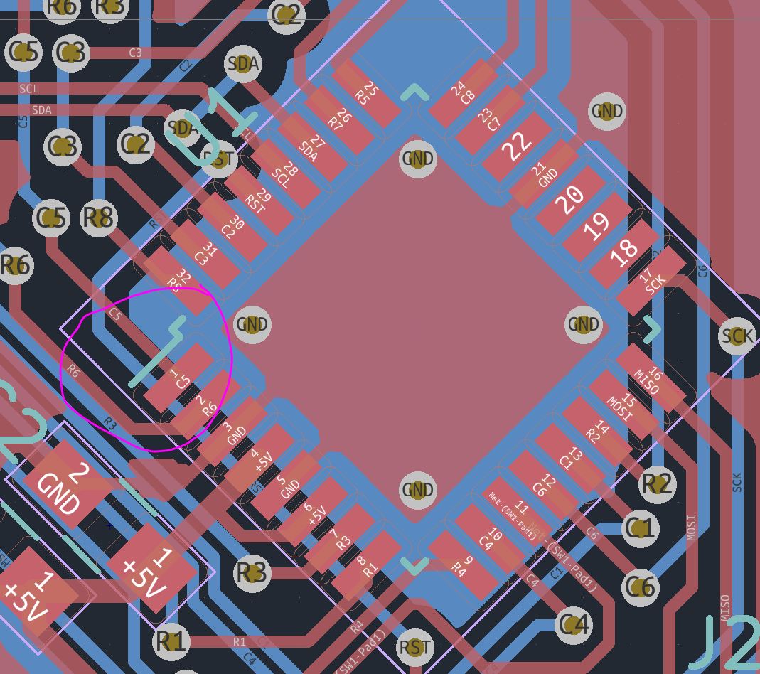
The one catch was that I had a lot of trouble finding the GYXM-788ASR LED matrix called for in the bill of materials. Fortunately adafruit sells a similar 8×8 matrix from luckylight. I tried to design around this by including both footprints, but I ended up mostly making a mess (and I still couldn’t find the 788!). Both are common cathode but the row/column nomenclature is flipped. To formatc’s credit, they did a good job with the firmware. It was easy to find pindefs.h, which let me swap around pins until I was happy. My strategy was to create a test pattern and make sure it shows up where you want it on the matrix. This was much faster than tracing every signal and creating the right pin definition the first time.
The second catch was that after programming, I couldn’t get the time to change! After glossing over the code it seemed like this must have something to do with the RTC- and after some gentle probing/touching the board it would occasionally work. Initially I attributed this to the crystal not starting up, but after many power cycles and other pokes, it seemed like the crystal would actually run just fine. As a last resort I read the datasheet, and lo and behold, the Vbat pin needed to be grounded.
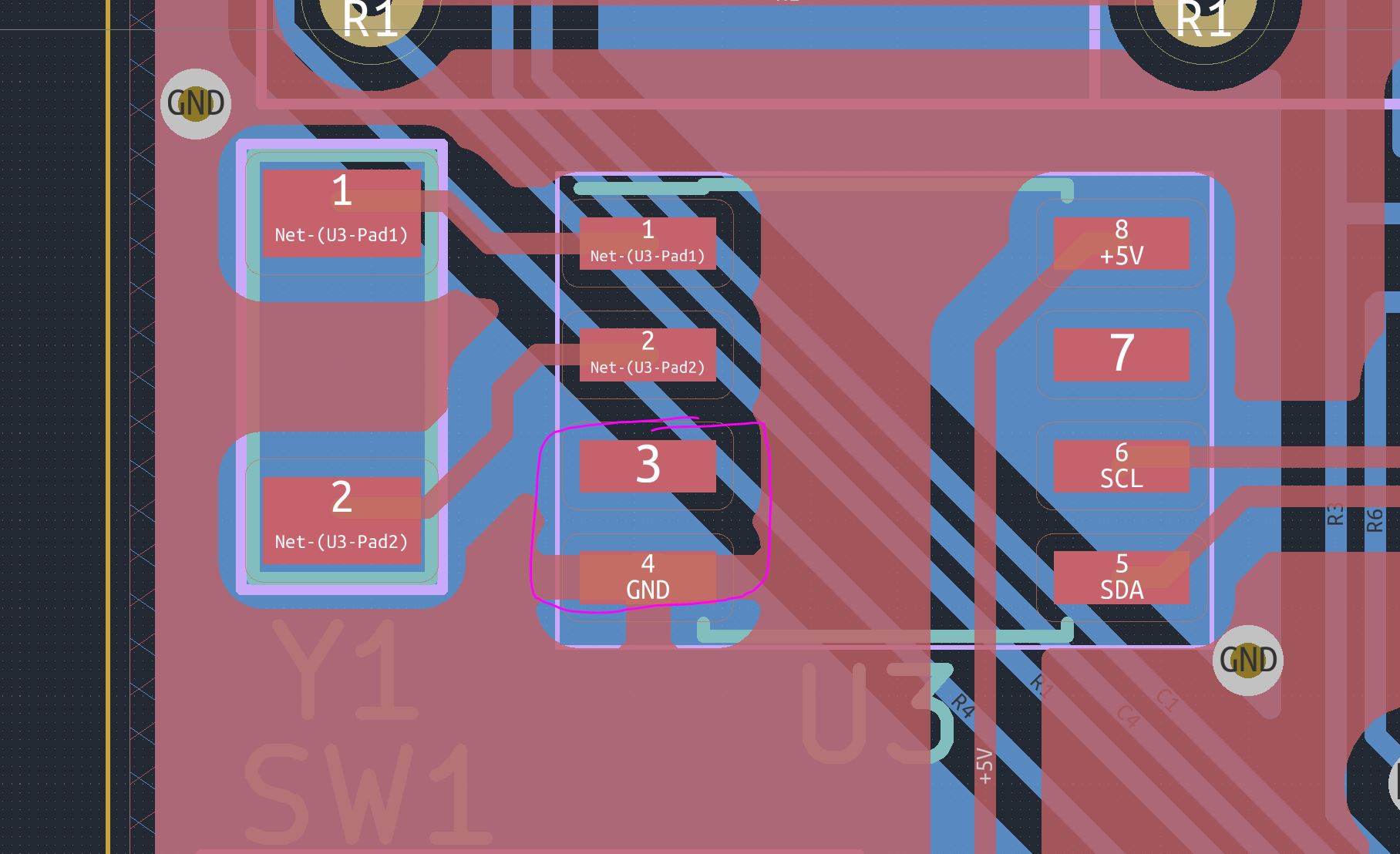
A blob of solder quickly remedied this deficiency in my pcb, and afterwards changing the time worked just fine. I suspect that sometimes the chip “just works” if that pad happens to be at the right potential on reset, but sometimes it doesn’t. The button presses update the RTC time, not a time on the micro. So if the RTC does not start up, then you can’t change the time.
Other Notes
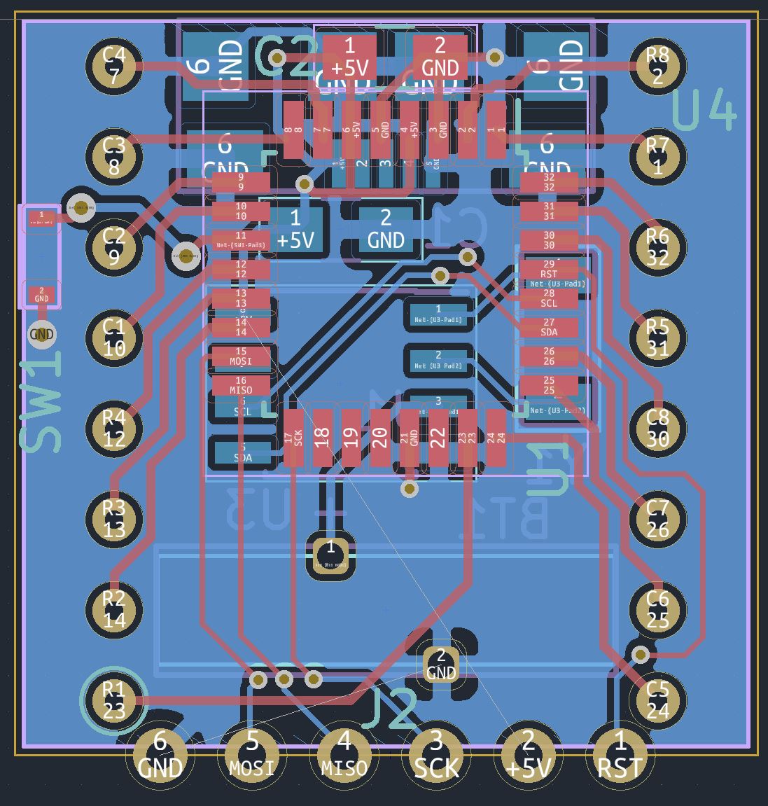
I used the default footprints from kicad for a lot of the parts, and the pin 1 designators are a little wishy-washy. They look more like an printing error than a clear indicator for pin 1. I guess I will get used to it instead of re-creating every part from scratch, but if I only have a few parts, throwing a dot on the PCB would go a long way during assembly.
I should have also added a polarity marking on the power connector, and a couple of i2c test points wouldnt have hurt either. Since this was a quick board just for me and the parts are big, I didn’t worry about it.
Upgrades for V2
I figured if I was going to do this board again, I may as well overdo it. I managed to cram everything into a board roughly the same size as the matrix itself, even after I added a coin cell and a USB connector for 5V power. The coin cell will keep the RTC running for about 10 years, even if it loses usb power. This way I can program it, ship it to someone, and they can just plug it in and the RTC will know what time it is. The ground plane is far from perfect but its about as good as I will get with a board this size
Since the time will basically never need resetting, the switch for changing the time is very very small. I used the NanoT switch which is about the same size as an 0805, which is very very small indeed. And because programming is now a one-time affair, I moved the programming header to castellated vias/PTH on the edge of the board. They .1″ pitch so they should be easy to solder to headers if I cant scare up a pogo pin jig for them. For some reason the ground pad shows an air wire. The 5V is purposely left floating since I don’t care about that connection.
Documentation
The git repo can be found here. Its probably not ready for prime time yet, but check the readme. I will update that when its reproducible.

2 thoughts on “The Micro Word Clock 2021 Edition”