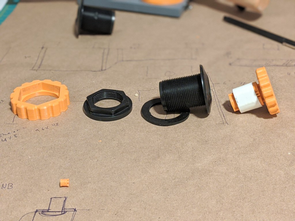
I recently had an issue with tightening bulkhead connectors. Since one side is round, its hard to really crank down on the nut that seals the flange! Grabbing the tiny, round flange just does not provide enough torque, no matter what you do. I am using these on a new counterlung design, so my goal was to make some small tools for assembling or breaking down the rebreather, but they needed to be hand-operated. While I did consider drilling holes in the flange and making a pin spanner that would be annoying since that is a sealing surface and because I would need to modify off she shelf parts whenever I got them. So I decided to build a arbor to grip the ID of the part.
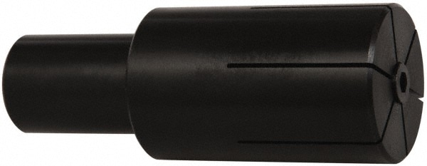
Typically an arbor is pretty simple- a wedge is screwed into a slitted block, and the block (in this case a cylinder) expands. This is pretty simple, and is a wonderful one piece construction. However, if you tried to print this it would be unlikely to work because of the huge stress concentrator at the root of the cut, and because you are creating a torque that is pulling right where the weak layer lines of the print would have to be!
Flexures are cool
My solution was to use single-extrusion-width flexures instead. A flexure is more or less a skinny piece of material that is bendy and stretchy…but on purpose. Because the material is thin, the maximum compressive and tension forces on the material stay small, even when the material is bent. Consider a piece of polycarb bent to make a face shield vs a sheet of bulletproof glass. If you bend one, it will spring back to being flat, while the other one will snap in half!
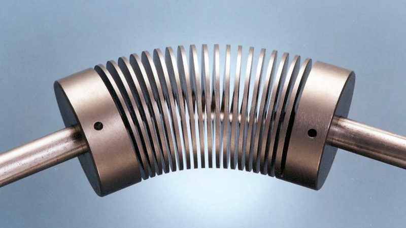
Another important note about flexures is that they can be very rigid in some directions, but flexible in others. That is how flexure motor couplings work- they are rigid in rotation, but flexible in other directions, as you can see. And since they (should) operate in the fully elastic region of the materials stress, they should also operate more or less forever, with no maintenance. This is highly desirable compared to multi-part assemblies.
However, flexures tend to be long compared to the amount of motion they can produce. A good rule of thumb is the length of the flexure (including total length of a zig zag) will be 10-20x the length you can expect it to move.
I had already done some experimentation with single-extrusion width flexures for a small parallel motion flexure, so I knew they worked. I had not tried to make a zig-zag of them, but I knew in theory the slicer would slice them and that they would be extremely flexible.
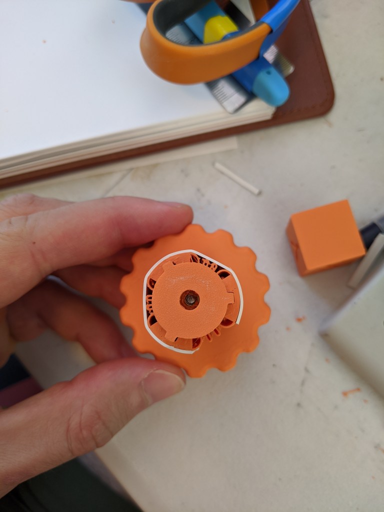
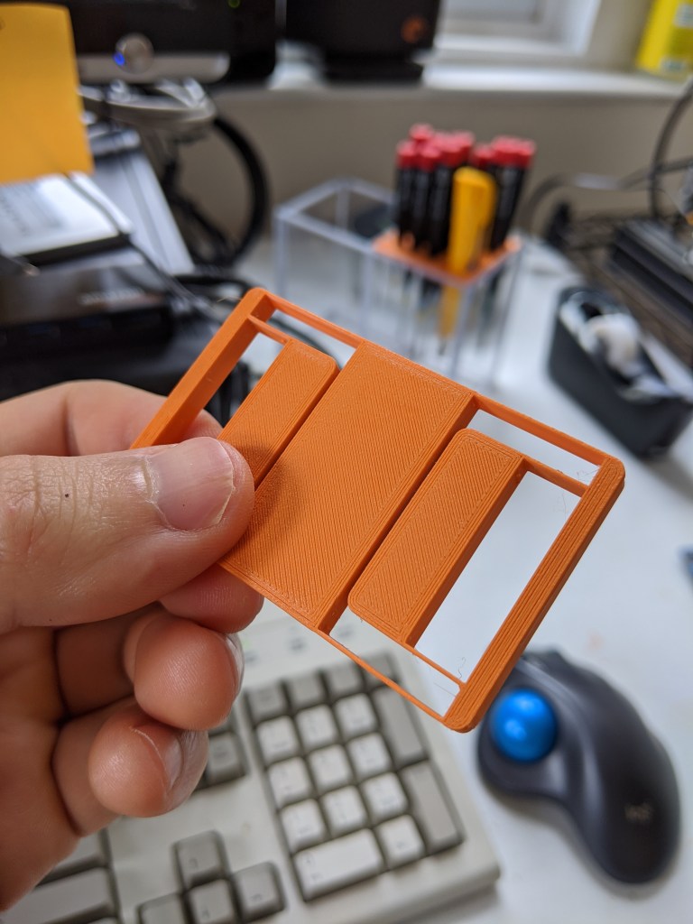
Here you can see the folds of the zig-zag flexure. To increase the amount of friction, I glued a piece of 1/32″ EPDM to the outside with superglue. Superglue seems to have ok bonding properties with superglue, as long as it is glued to something rigid. I could probably peel the EPDM off of the mandrel if I wanted, and in previous tests the EPDM has failed, not the superglue (CA glue). One thing to note is that some of the zig-zags are actually stuck together by stringing on the 3d printer- this is really annoying, and this design would benefit from better retraction settings, or more space between lines.
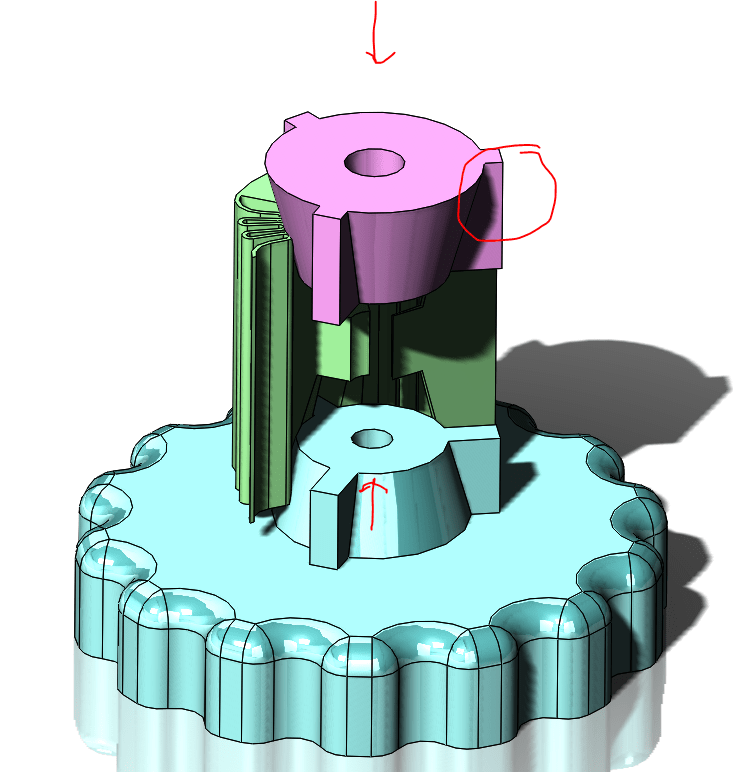
Here you can see how it works- two cones are pulled together, which acts on a conical surface in the arbor core. This pushes the wedges outward, and into the ID of the part. This is achieved with a heat-set M3 insert on one side, and a long m3 bolt that goes through the whole assembly. While it would be possible to have just one wedge, I thought that two would be better since it would prevent twisting the flexures and create an expanding cylinder shape instead of an expanding cone shape.
Another critical feature seen here are the fins on the cones that go into matching slots in the flexure. These prevent the nut from spinning freely, and it also allows transmission of torque from the handwheel to the arbor, once the wedges are locked in place rotationally.
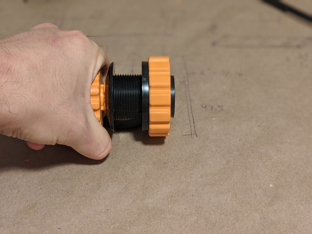
Here it is in use. the large diameter of the bottom wedge is for gripping- it is about the same size as the grip for the nut, and by using these two the nut can be tightened about as tightly as I could want.
Notes for successful flexure printing:
-make the width of the flexure the same width as your nozzle/whatever width your printer thinks it is printing
-flexure bending axis will be paralell to z axis for this technique. I could imagine a way to make a flexure on the build plate but that’s different than this technique
-try to convince your slicer to prioritize outside “skin” layers, including the flexure.
-Explicitly tell the slicer not to put the z-seam on the flexure. While flexures are bendy, the z seam in theory/in practice is thinner and weaker, and putting it on a flexure is a good way to snap it. A few seams here and there are ok
-Attempt some kind of strain relief where the flexure goes into the part-put a biiiig radius on the flexure before that point. since we are relying on a single width of filament to bond to the rest of the shell here, adding a radius here probably wont help since even the smallest printable radius is much much stiffer than a single wall thickness.
What I would do differently/what went wrong
The flexure I made is pretty aggressive in terms of width between folds. I could probably go down to fewer folds since the wedges dont need to move very far. This would give me more clearance between lines, which would help with the stringing issue Or I could even go down to just two wedges, which would give me a lot of room for flexures and could even give me some extra surface area.
Additionally, the angle of the wedges is a little narrower than some previous prints. This makes them tend to get stuck, as less of the restoring force of the flexures is pushing them up and back out of the cone of the flexure. Its only about a difference of 8 degrees included angle, but it is significant. This makes it a little fiddly to get the flexure out of the hole once it has been set. this could be improved by reducing friction between the printed surfaces, but it seems simpler to make it work right off the printer. It would be distracting if you were servicing something using the tool.
I will also probably change to some kind of hand-operable and fully captured screw. as it is, it requires an additional screw (allen key) to actuate the clamp. While that is ok, it would be very convenient to have a clamp that did not require a small, easily corroded tool, and it would be nice if the screw couldn’t fall out.
