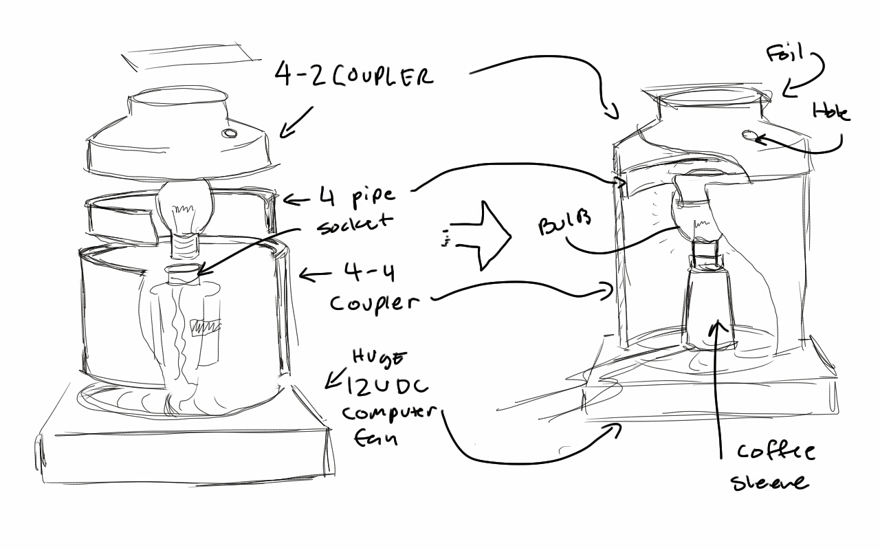
Exploded/Cross sectioned view of assembly
There are three main parts to this documentation: hardware, electrical, and software. A usage post will follow this one. A paste of the complete code is included at the end and is intended to be run on the arduino uno. Consult the hardware and electrical bill of material lists at the end of the post before going to the hardware or electronics store if you attempt this build. It details what parts should be available at what store- some things like lamp cord are hardware items, even though they are electrical parts by nature. Each section also contains recommendations for improving the device at the end of the section. Read these if you want to make your device better/more durable. As usual, I am not responsible for your actions or accidents if you choose to build this.
Hardware:
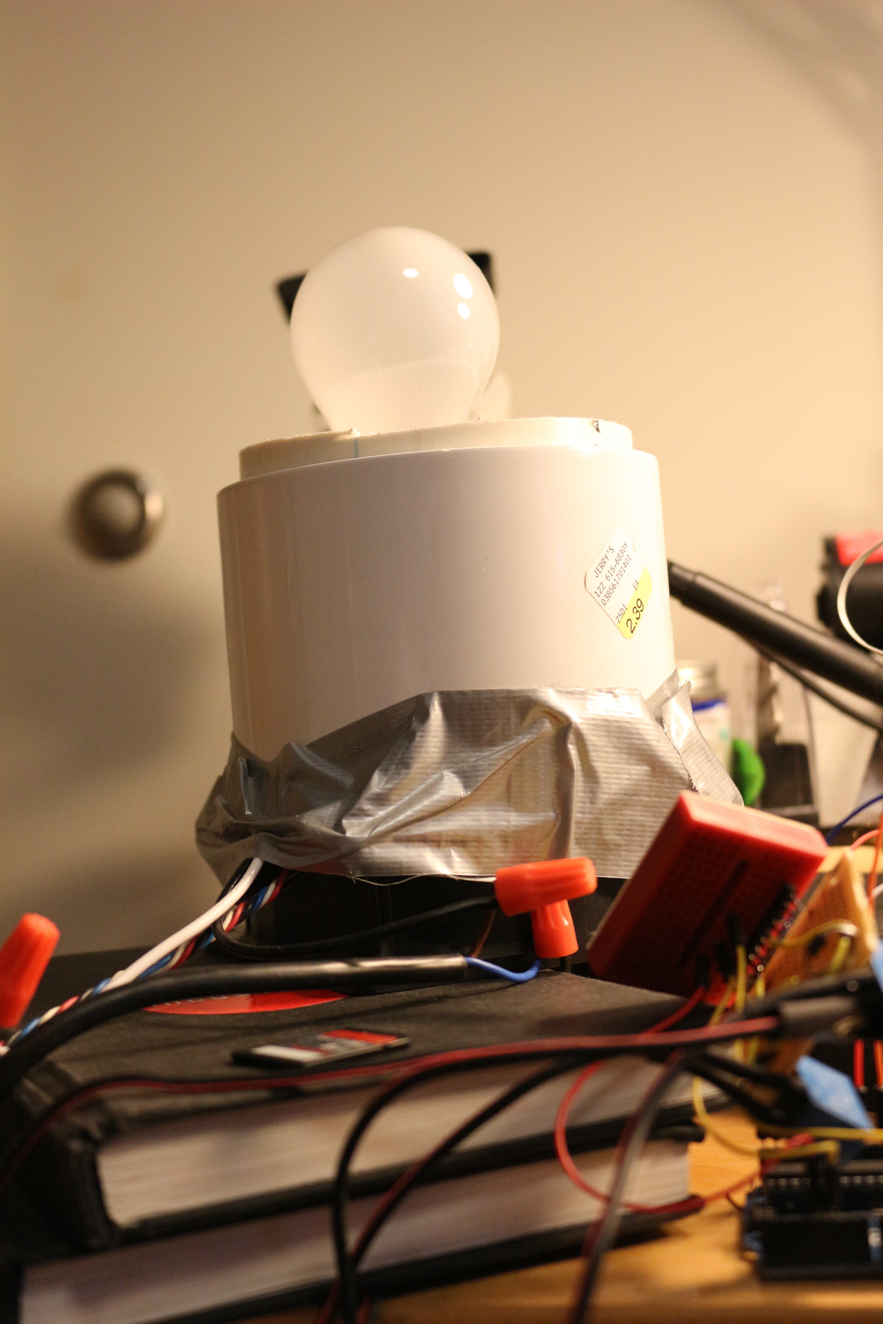
4″ pipe creates a place for the lid to sit
The body of the cycler is made of three pieces of PVC pipe. Note that nominal PVC pipe sizes refer to (mostly) ID and not OD. I think this pipe is schedule 80, but I could be wrong. The base is made of a “4 coupling” which is a part that holds couples two 4″ pipes together. This is attached to the lid that holds the samples, made of 4-2 reducing coupler, which reduces the pipe size. These are connected by a small piece of 4″ pipe. The pipe should be jammed as far as possible into the 4 coupler as possible, and should expose about .5″ of pipe above the lip of the coupler to make a flange the lid can sit on. See above photo.
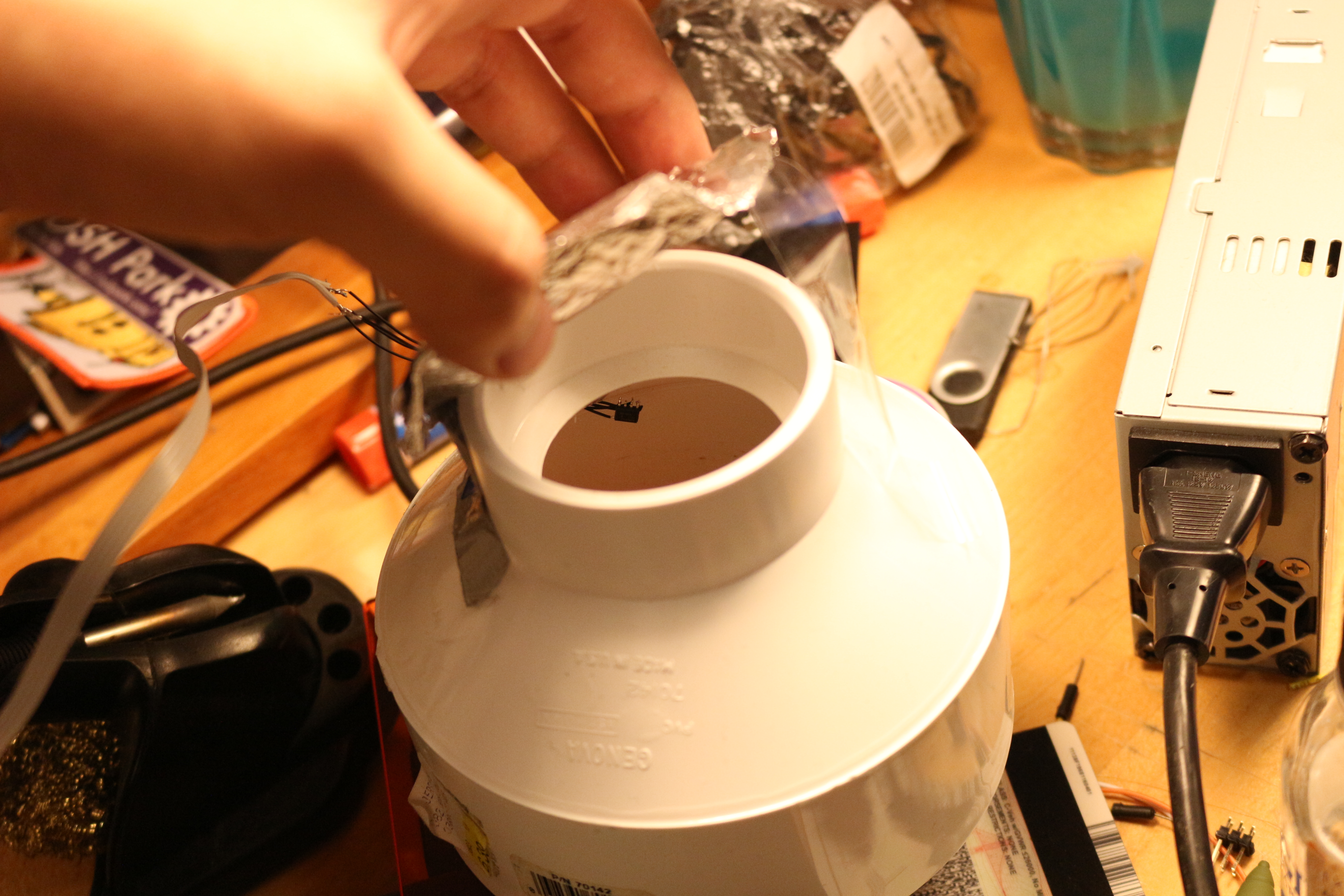
LID IS IMPORTANT
The lid currently has one .25″ hole on it, which was made to hold samples or route the temperature sensor wires. Since I didn’t want to drill more holes, I just scotch taped my samples inside the lid, along with the sensor, and routed the wires through the hole. One key thing that you cannot omit is the aluminum foil flap at the top (2 side) of the lid. This flap prevents convection during the heating cycle and allows air to escape during the cooling cycle. If it is omitted, your device may struggle to reach the higher cycle temperatures unless your rooms ambient temperature is very high.
Recycling!
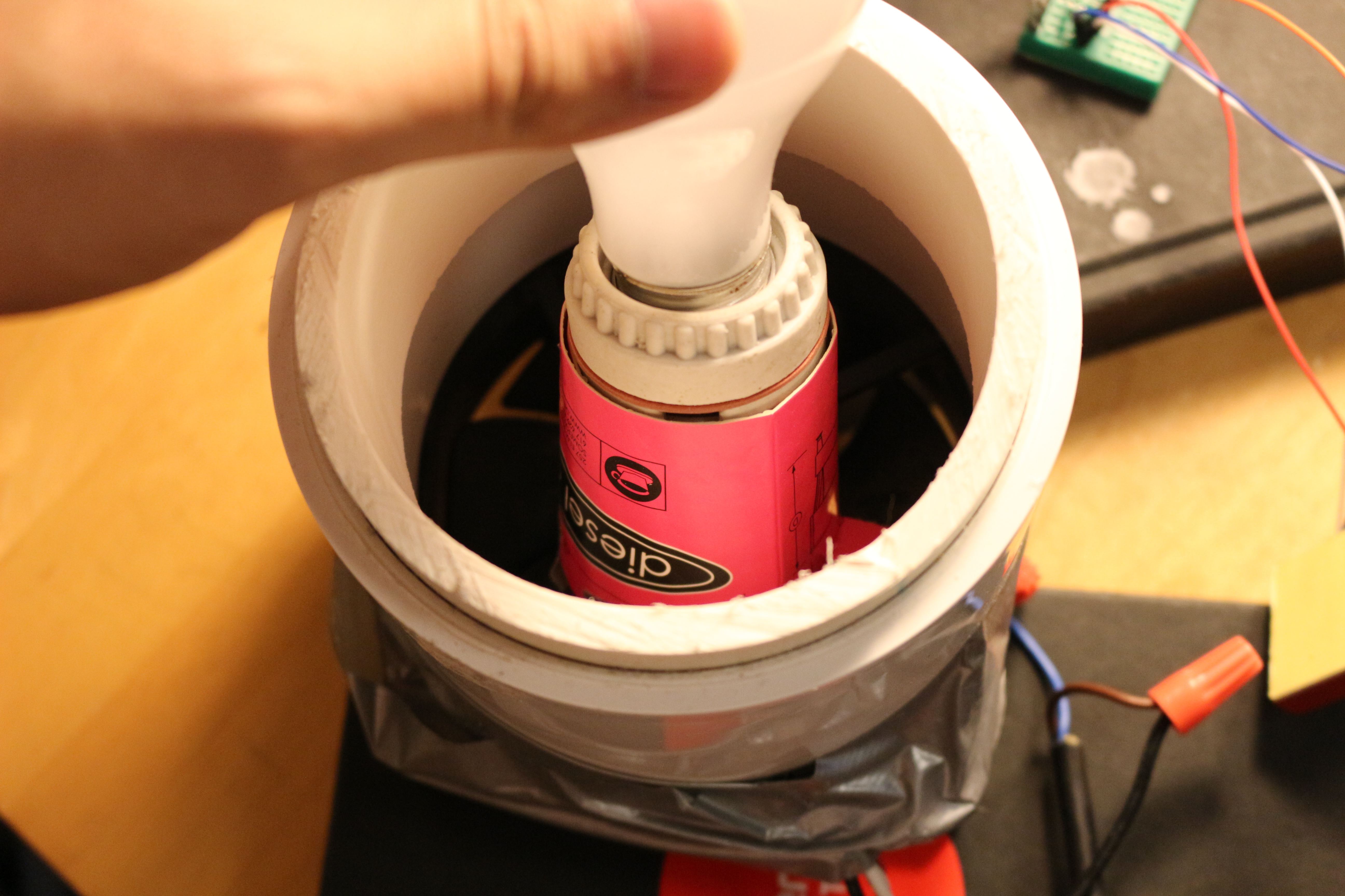
The next thing to discuss is the lightbulb. I had a 60w incandescent lightbulb, of the cheapest variety possible. It is screwed into a bulb base of the variety that hardware stores sell to make custom lighting fixtures, and is attached to two wires like a lamp cord. It is positioned over the fan using a rolled up coffee cup sleeve. Our coffee cup sleeve came from the local eatery Diesel Cafe, which serves both delicious coffee and useful sleeves.
On a wire test tube rack at BOSSLAB
The fan is a 100mm fan from a computer, approximately the same size as the 4″ pipe. It is duct taped to the pipe, and it is tremendously loud. It us suggested that the machine be propped up on books or a wire rack to allow air to flow into the fan.
Hardware Improvements:
To improve heating times, do not drill a hole for the sensor wire. Drilling such a hole provides a path for convection currents to take heat out of the system. Instead, make a small notch in the interface between the lid and the 4 coupler to route the sensor wires.
The next obvious improvement is to get a bigger bulb. However, there are tons of other resistive heating solutions out there that don’t use a delicate, gas filled glass bulb as a heater. Heating blankets for example, use flexible wires that would work way better for this application, and could allow each tube to have its own personal heater, sensor, and feedback loop! Unfortunately, you can’t just buy a new custom wire heater at CVS.
Besides that, the connection between the fan and the coupler and the connection between the lightbulb and the fan could be improved. Duct tape is fine for my build because I really only want it to work once. An easy solution would be 3d printed brackets, or some small sheet metal adapters.
Electrical:
Electrically this thing is dead simple. However, it does deal with dangerous voltages- 120 VAC or whatever your local mains is. If you do this be careful! Never ever work on the wiring while it is powered up.
Really poorly connected relays are a holdover from old build. Heatshink is solid though!
Basically, there is an arduino with two relays and a single i2c temperature sensor hooked up to it. The relays have four pins. When current flows through one pair of pins, the other pair of pins connect to each other. so one side of the relays goes from a digital pin to ground, and the other side interrupts whatever the circuit you want to turn on and off. Other devices can do this, but relays are cheap, hard to destroy, and are readily available. Note that the fan needs a 12v power supply via a wall wart, while the lightbulb needs to be connected to 120vac. We used a few wire nuts, but I highly recommend wago lever wire nuts instead.
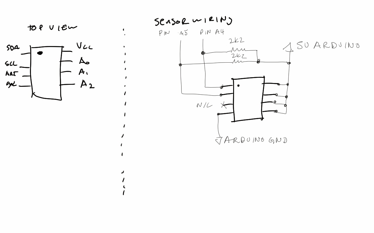
Here is the documentation for wiring the relays. Be sure that there are no bare120 VAC connections by covering them in heatstroke tubing.
at30ts750 free soldered to wires.
The temperature sensor is an at30ts750 in SOIC-8. It is a wonderful and cheap sensor and comes in a variety of sizes. It talks over i2c to the arduino, and requires 5 and ground, giving it a grand total of 4 wires. But as you can see, there are 8 pins! Don’t worry. Pin 3 is an alarm that is not used, and 6, 7, and 8 are the last 3 values of the i2c address. For my purposes, I soldered them all to Vcc (5v), making the 7 bit address 0b1001111. The first four bytes, “1001” are the same for all sensors of this type.
As you can see, the chip is soldered to small solid core wires. This was done to try to match the thermal impedance of the tube better. Large sensors with lots of mass take time to heat up, and the tube take a different amount of time to heat up. The only way to measure the temperature of the tube is to put a sensor in it, or to estimate the temperature with a sensor of similar thermal mass. I guesstimated the matching based on sizes of sensors I had available. UDFN-8 seemed too small so I went with soic-8.
All of this connects to an arduino, which theoretically connects to your computer. You don’t actually need the computer unless you want to log the temperatures, but the arduino does need power! Don’t forget that.
Electrical improvements:
Let’s start with the relays: they were chosen because you can get them anywhere, and because wiring two relays is really easy conceptually for people who have never worked with electronics. But a transistor would suffice to drive the fan, and a solid state ac line switch might be more elegant than a relay for the bulb. These are probably a slightly cheaper (depending on source/ratings) than the relays, and could provide proportional control of the fan or PWM the bulb.
A cheap wiring/durability improvement would be a proto shield or a relay shield for the arduino. They may be overpriced in a lot of ways, but they are very convenient and can clean the wiring up, which is nice if you are going to use it frequently. If you wanted to go all-out you could design a custom PCB.
Software:
Software deals with a lot of the complexities of this system, including temperature control, temperature sensing, and timing. Each time you change your cycle parameters, the code needs to be recompiled and uploaded. Each of these paragraphs is meant to comment the code in more detail, with some code snippets pasted in. There is also a section for people who are not familiar with programming but want to use this code. Complete code available at the end, and soon on github.
int temp_task(float target,float temp)
{
if(temp<(target-tol))
{
digitalWrite(FAN,LOW);
digitalWrite(HOT,HIGH);
}
else if(temp>(target+tol))
{
digitalWrite(HOT,LOW);
digitalWrite(FAN,HIGH);
}…
Temperature control is handled with a simple bang-bang controller. The control loop runs every 250 ms, which is fast enough to stay within about +/-.5 degrees. The acceptable band of temperatures is also +/-.5 degrees. A hysteretic controller was chosen because it worked, and I wanted to finish this instead of tuning a PI controller.
float get_temp(int address) {…
Wire.requestFrom(address,2);
while(Wire.available())
{
upper= Wire.read();
lower= Wire.read();
raw = (upper << 4 ) ^ (lower >>4);
temp=(float)raw*.0625;…
Temperature sensing was done on an at30ts750, which can supply up to 12 bit temperatures (default is 9) in twos complement. There is some brief setup code at the beginning of the main loop. This is to change the value of the volatile configuration register of the chip so it returns 12 bit values and not 9 bit values. I didn’t write to the non-volatile memory because this chip is going back in the parts bin, and I don’t want non-default vales written to it.
Since it the i2c transactions happen a byte at a time, there is some code to shift out the trailing 0s and stitch the two bytes together. Negative numbers a la twos complement are not implemented, since unless your room is negative degrees C ambient, there are no subzero temperatures to read. At the end of this the temperature value is computed by taking the raw sensor value and multiplying by the conversion from adc ticks to deg. C.
for(int i=0; i<seconds*8; i++){
temp=get_temp(0b1001111);
Serial.println(temp,DEC);
temp_task(target,temp);
delay(125);
}
Timing is done by taking a loop and putting a delay in it. Interrupts would be nice, but it is way easier to just use delay, and this project is just to prove it can be done. Basically, every that loop calls get_temp and passes the temperature to control_task also has delay (250) in it. The time of the delay dominates the loop. This is not very safe because the sensor could possibly not reply, and that would cause the loop to hang.
For those of you not well acquainted with programming, it is still simple to change the PCR parameters. There is a function called single_cycle(temp, time) that ramps to a temperature in Celsius, then holds it there for the specified time in seconds. The temperature should not exceed 100 C and the time cannot exceed 30 seconds. To make it longer than 30 seconds, just have call single_cycle multiple times.
You will notice that my code does not have each pcr step pasted into it. That’s because the cycling in pcr is the same three steps over and over again- denature, anneal, and extend. These three steps live in the for loop. To add or change the steps, edit what is in the for loop by changing the parameters of single_cycle, or adding more cingle_cycle calls. To edit how many times it happens, change the line “#define CYCLE_REPEATS 30” that is at the top of the file. Just change the 30 to the number of cycles you want. If you want to add things before the cycling, or after, just add single_cycle calls before or after the for loop. Check the comments (the things after the //) in the code for where to add stuff before or after the loop.
Code Improvements:
Well for starters, you could have interrupt driven timing events, and a state machine instead of a bunch of nested loops. This might make the machine more accurate time wise. The code could also be improved to take some kind of array/serial data that encodes the cycles, so you don’t have to edit and recompile it for each different annealing temp. The final thing to add would be input sanity checks on the single_cycle function, so people don’t go putting in a temperature of 200 or anything crazy, and saftey functions to prevent overheating, emergency stop, and pause.
Bill of Materials:
Hardware:
- Duct tape. Get the good stuff- 3M
- 4″ long piece of 4″ nominal diameter PCV
- 4-4 PVC coupler
- 4-2 PVC coupler
- aluminum foil
- coffee cup sleeve, or paper plate
- lightbulb, 60W or greater
- lightbulb socket
- lamp cord- this is just insulated 2 conductor cord used in lamps
- Wire nuts or wago lever nuts
- heat shrink is sometimes found at hardware stores
Electrical:
- Arduino uno
- at30ts750 or any digital or analog temperature sensor that is handy*
- two relays capable of 12v .5A DC and 125 1A VAC. The OJE-SH-105DM is suitable*
- two resistors for pulling up the i2c lines. 2.2k ohms each, any tolerance*
- heat shrink
*These items are available on digikey. Part numbers AT30TS750-SS8-B-ND, PB874-ND, CF14JT2K20CT-ND.
ETC Items:
- Thin walled reaction tubes
- PCR reagents- I used this master mix, which conveniently has electrophoresis tracking dye built in.
- Template DNA and Primers
Here is a copy of the code- I will get around to posting it on my github once I remember the password. Fortunately, this is not python, so whitespace does not count!
#define CYCLE_REPEATS 30
#define tol .5
#define HOT 5
#define FAN 4
#include <Wire.h>
void setup() {
Wire.begin(); //join bus as a master
Serial.begin(9600); //start serial port to computer
pinMode(HOT,OUTPUT); //set hot and fan pins as outputs. Default is low.
pinMode(FAN,OUTPUT);
}
//get raw value from sensor, convert it to temperature and return it as a float
float get_temp(int address)
{
unsigned short upper, lower, raw;
float temp;
Wire.requestFrom(address,2);
while(Wire.available()) //read data from sensor as a 12 bit twos complement. since this application will always be at ambient temperature, we dont need to worry about the sign.
{
upper= Wire.read();
lower= Wire.read();
raw = (upper << 4 ) ^ (lower >>4); //get rid of trailing 0s
temp=(float)raw*.0625; //each ADC “tick” is .0625 of a degree.
return temp;
}
}
//this is the function that decides what the machine will do- heat, cool, or idle. the #define tol .5 at the top can be changed to an arbitrary tolerance.
//making the tolerence too small will result in your machine flipping between heating and cooling really fast, making it too big will result in more ringing
int temp_task(float target,float temp)
{
if(temp<(target-tol))
{
digitalWrite(FAN,LOW);
digitalWrite(HOT,HIGH);
}
else if(temp>(target+tol))
{
digitalWrite(HOT,LOW);
digitalWrite(FAN,HIGH);
}
else
{
digitalWrite(HOT,LOW);
digitalWrite(FAN,LOW);
}
return temp>(target-tol-tol) && temp<(target+tol+tol); //return 1 if temp is within 2 tol- approaching switchover pt. from ramping to waiting for the timer
}
//this function ramps (heats or cools) to the desired temperature, then waits a certian amount of time while holding that temperature
void single_cycle(int seconds, float target)
{
float temp;
temp=get_temp(0b1001111);
Serial.print(“BEGIN\n”); //prints this at the beginning of every cycle, useful for debugging
Serial.println(temp,DEC);
while (!temp_task(target,temp)) //while temperature is not near the target, keep ramping and checking the temperature. delay makes each cycle take about 1/8 of a second
{
temp=get_temp(0b1001111);
Serial.println(temp,DEC);
temp_task(target,temp);
delay(125);
}
for(int i=0; i<seconds*8; i++){ //seconds*8 since this loop takes about 1/8 second. holds at the desired temp for the desired number of seconds
temp=get_temp(0b1001111);
Serial.println(temp,DEC);
temp_task(target,temp);
delay(125);
}
}
void loop() {
float temp, target;
target=25; //arb target temp, just so the thing doesent go crazy it is set to about room temperature
//these wire commands set the prescision of the sensor to 12 bits
delay(1000);
Wire.beginTransmission(0b1001111);
Wire.write(0b00000001);
Wire.write(0b01100000);
Wire.endTransmission();
Wire.beginTransmission(0b1001111);
Wire.write(0b00000000);
Wire.endTransmission();
int time=0;
delay(1000);
//prints start at the beginning of the cycle
Serial.println(“START”);
//add stuff here that you want to do before the cycle, eg hot start, initial denaturation
single_cycle(30,98);
//this for loop is what gets repeated over and over again, change #define CYCLE_REPEATS 30 to change it
for (int i=0; i<CYCLE_REPEATS;i++){
//change what is in here to change what the denature-anneal-extend cycle is.
single_cycle(10,98);//denature
single_cycle(30,71);//anneal
single_cycle(30,72);//extend
}
//Final extension etc. goes here. Note repeat to get correct time.
single_cycle(30,72);
single_cycle(30,72);
single_cycle(30,72);
single_cycle(30,72);
single_cycle(30,72);
single_cycle(30,72);
single_cycle(30,72);
single_cycle(30,72);
single_cycle(30,72);
single_cycle(30,72);
//this block turns off the fan and bulb and waits for the device to be reset
digitalWrite(HOT,LOW);
digitalWrite(FAN,LOW);
while(1){
Serial.println(“IDLE”);
}
}

your circuit diagram shows the relays being directly driven by the arduino (pins 4 and 5). the relay you spec and show is the oje-sh-105dm which has a coil draw of 91mA. since the arduino has current max of 40mA per i/o pin how do you keep your arduino alive? it also appears that you have a diode across the relay coil, but it’s not listed in the parts list; have you eliminated it?
Good catch. Turns out that the arduino has enough power to drive it. I made this out of spare parts, and thats what I had, so that is what I used. There is in fact a diode, but I neglected to include it in the documentation. Its just a snubber diode to prevent too much current from sloshing around into the arduino.
–A