I am an Engineer in the Boston area. I like making things, teaching people how to make things, and tea. This blog is documents the things I make and do, and provides instructions on how to do the things I do, or make the things I make.
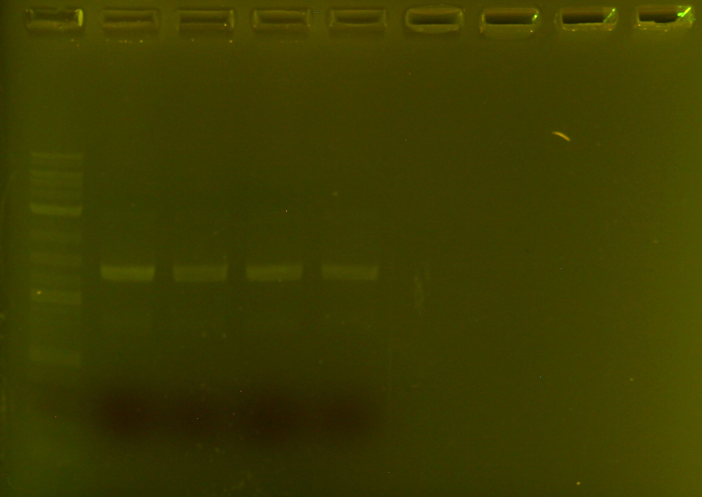
Following this weekends failed restriction enzyme digest, I thought I would try again with no heated lid, and with a longer incubation time. I am using HindIII-HF, so I can apparently let it sit overnight without too much star activity (non-specific cutting). Since I used quite a bit of my PCR product last time around, I thought it would be a good idea to re-PCR my gblock. After a picture-perfect gel (above)
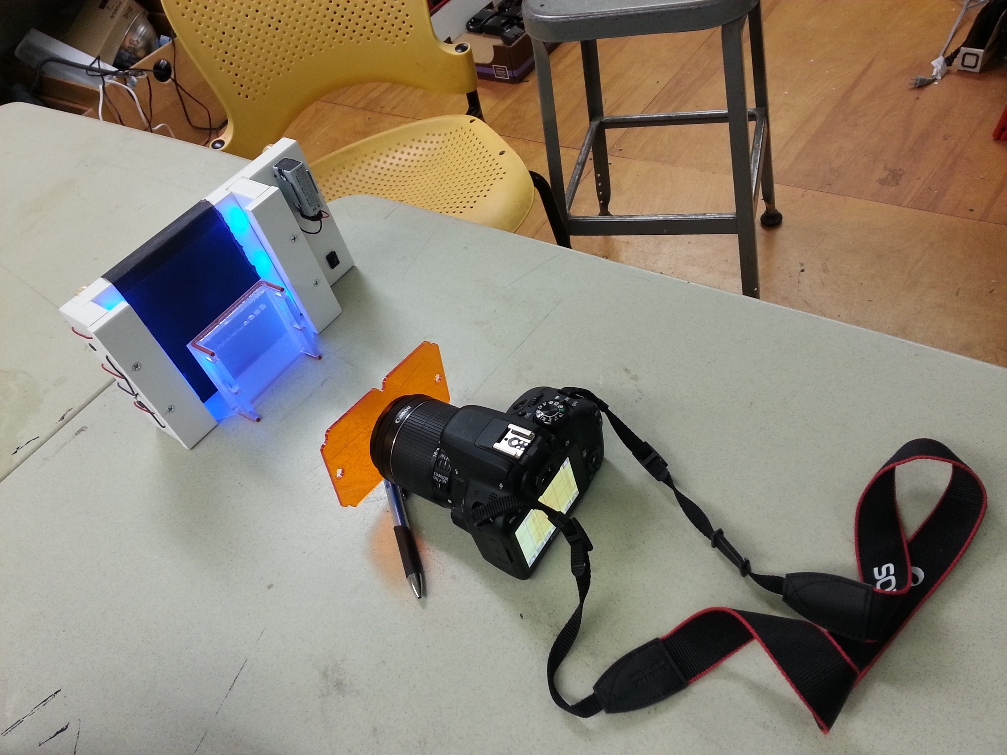
Speaking of pictures, here is how I do my gel documentation. I just shoot my Canon SL1 through an orange piece of acrylic, at the gel. I set stuff up roughly like this, then I turn off all the lights and take a long exposure. With this method, I have been able to visualize 100ng samples of DNA regularly, although you can also see bands of half that mass. I am wary of claiming I can visualize a band below 100ng since it was very faint and I had the aid of another identical lane later in in the gel when I did it, so it was easy to pick out against the background, which let me adjust the exposure to get a better picture of the band.
Anyway, I just put in my digest to run overnight at 37C. I will heat-inactivate it at 80C for 20 minutes when I get back to the lab, and run it on another gel! Time to go home!
It actually took me a day or so to accept my restriction digest had failed, and it took me a few hours to guess why it did not work. What I wanted to do was digest my plasmid and my gene with HindIII (in separate reaction tubes). This would leave HindIII sticky ends on both. At the same time that I was digesting the plasmid, I wanted to also dephosporylate it so it would not re-circularize (stick to itself during ligation). To verify that I cut the gene and the plasmid, I ran them on a 2% gel. I expected that if I ran to the end of the gel, I could get separation between the cut and uncut genes, as the difference is about 150 bp. I also expected the uncut pUC19 plasmid to run much faster than the cut pUC19. Alas, this was not the case.
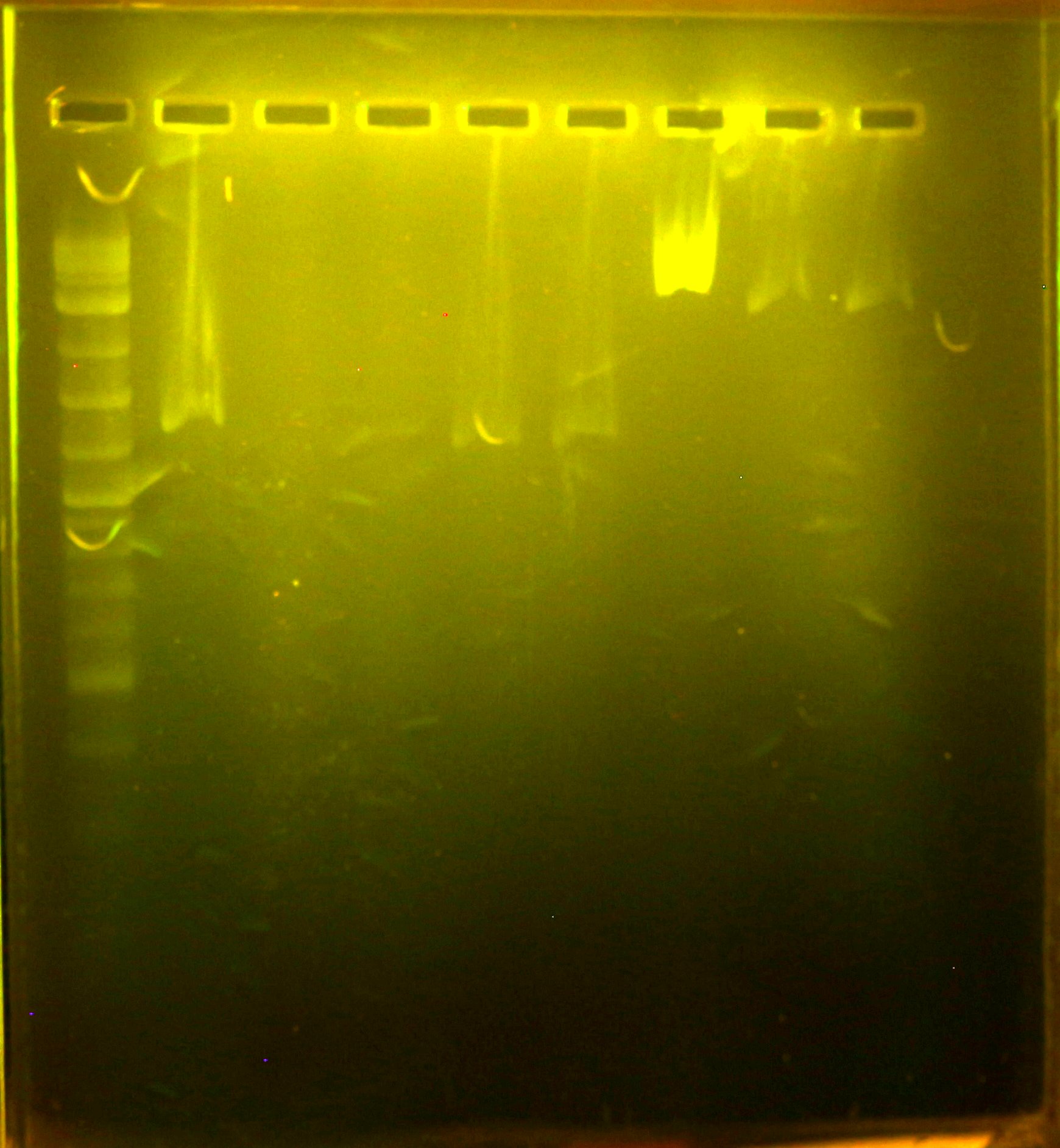
Gel Analysis:
lanes numbered from right to left. 2% agarose gel, with safe gel stain
What a mess. Seriously, this is a pretty gnarly gel. Anyway, from left to right the loaded lanes are:
2 log ladder
un-cut bg fragment
empty
empty
cut bg fragment 1
cut bg fragment 2
pUC (way overloaded…)
cut pUC A
cut pUCB
As you can see, the cut fragments of pUC ran faster than the uncut fragments. This is very suspect, since the supercoiled plasmid DNA should be “smaller” than the cut DNA. It was not a small amount either, it looks like it ran somewhere between 1k or 500 bp faster. This could be due to over loading but it is not a good sign.
The cut fragments of the gene did seem to run a little faster, but the gel is so gnarly it is hard to tell. They do look like maybe they got cut, but it is hard to tell when the bands are so misshapen and far apart. It would be no good to try to ligate them to an un-cut plasmid. So I need to troubleshoot this step.
What Is Wrong:
I strongly suspect that my restriction enzyme digest was foiled by the heated lid of the pcr machine. It heats by default to 114C or so, to prevent condensation on the lids of the tubes as you get up to 98C or so. I had it on at full blast- the inactivation temperature for HindIII is 80C, and I used the “time saver” protocol and only digested for 30 minutes. So what did not get inactivated had little time to get its enzymatic work done.
I have finally received my gBlock shipment from IDT. A gblock is guaranteed to be 200ng, which is a little nerve wracking to work with- it is not a small amount of DNA, but it is not a huge amount of DNA either. A colleague at BOSSLAB suggested that I add PCR priming sites to the end of the synthesized DNA, to let me amplify it before diving into cloning. This post explains how I amplified it, and what kind of yield I got, and how I tested that I got the “right thing”.
I chose to add standard 17-mer universal primers to my sequence, so along with my gBlock, I got two tubes of primers. I chose to use Q5 polymerase because it is the highest fidelity polymerase that NEB sells. For a “typical” PCR reaction, NEB recommends re-suspending primers to 10uM, and using less than 1000ng for template. Since all my DNA was shipped dry, I needed to first resuspend my samples to the proper concentration, then run PCR and verify that I had made the correct product.
Resuspension:
IDT conveniently tells you how many nanomoles you have been shipped. To get a 10uM concentration all you have to do is add as many ml as you have nanomoles, since 1 nanomole per milliliter is 10uM. So, after a brief (5 seconds or so at 5k) spin to make sure all the dry DNA is at the bottom of the tube, then I added some water, at 1ml per nanomole. Unfortunately, I had 3 or so nanomoles- and the tubes can barely fit 2.5 ml. So I resuspended in 1ml of water, split the resuspended DNA into an extra tube, and then brought both tubes up to the correct 10uM concentration. IDT ships you a lot of primer if you order custom oligos.
Resuspending the gBlock was a little scarier. Unlike the primers, the gBlocks are not visible in the tube (as far as I can tell). So after a quick spin, I shot 20ul into the bottom of the tube and pipetted up and down to mix.
PCR:
With everything resuspended, it was time to set up the PCR! Fortunately, NEB has awesome protocols on their website, so it was easy to set up. The Q5 even comes in a 2X master mix, so it was easy to pipette! I made two 50ul reactions:
25 ul 2x Q5 poly master mix
2.5 ul m13 forward primer (10uM)
2.5 ul m13 reverse primer (10uM)
1.0 ul template DNA (10ng/ul)
19 ul PCR water
The PCR program was run with a pre-heated lid (114C) and a hot start (98C). The annealing temperature was determined with the NEB Tm calculator. I ran 30 cycles of:
30s detnaturing at 98C
15s annealing at 57C
45s extension at 72C
There was a final extension of 72C for 5 minutes, and then a final hold at 4C.
Gel Analysis:
A 1% agarose gel with 5 ul of 20,000X “Safe DNA Gel Stain” (from bioland scientific, via the odin) was prepared. Four lanes were run- 5 ul of 2 log ladder in purple dye, PCR product 1 and 2, and then 1 ul of 2 log ladder in purple dye. The PCR product was expected to be 1k3 bp, and you can see it right in between the 1.2 and 1.5 kb bands in the 2 log ladder.
For those interested in how sensitive the DNA stain is- those bands on the bottom are from NEBs 2 log ladder. From left to right, the first band is about 40ng/ul. As you know, the top band has 5 ul of ladder loaded, while the bottom has 1 ul of ladder. That means this is a photo of the position of 40 ng of DNA. I was impressed by the sensitivity, especially because this was not shot under ideal conditions- I did this in a dark corner of a room, under the shade of some paper I found lying around. With a better setup, I think the 40ng bands could look even better!
The very observant reader may notice some faint bands in the second lane from the top, which correspond to the ladder on the top. This gel tore across the lanes when I separated it from the casting apparatus, and I think some of the top lane leaked into the neighboring lane. Fortunately, the PCR products are in a different position and at a different intensity than any of the ladder bands, and UV spectrometry verified that there was DNA that was amplified.
DNA Quantification by UV Spectrometry:
While we do not have a nanodrop, we do have a genequant. Just like a nanodrop, it is a UV spectrometer that is specifically designed to quantify DNA/RNA in samples. Unlike a nanodrop it requires at least 50 ul of sample for the cuvettes that we use. Since the DNTPs and proteins left over from a PCR reaction will also absorb UV wavelengths, and because PCR buffers and enzymes can have non-specific and unwanted activity later on, there is such a thing as a “PCR cleanup kit”, to extract out the product of your reactions. Unfortunately, this kit will also concentrate the reaction products into smaller volumes, around 25 ul. I combined the two samples eluted from the cleanup kit and measured them in the spectrometer, which told me I had .071ug/ul, or 3.5 ug total. That is about a 350 fold increase in DNA! I thought that was pretty good.
With PCR product in hand, the next steps in cloning involve cutting, de-phosphorylating the backbone, and ligating the insert into the backbone.
I have been shooting and scanning film on a regular basis for about a year now, so I thought that I would weigh in on the two most widely available cheap films, koduak ultramax 400 and fuji superia 400. Both are available at CVS/Walgreens/Rite aid, occasionally in overpriced rolls, or even higher priced disposable cameras. In fact, this post was spurred by my friend using one such camera, and me remembering that UltraMax exists.
Whatever way you decide to go after this review, my recommendation is to go online and find where you can buy it in bulk- I have found if for as low as about 2.50 per roll (fuji) and 2.00 per roll (kodak).I use film to capture things and people I find interesting, but I don’t take pictures every day. I use an Olympus XA, which floats around in my bag and gets fished out every now and then for a photo. I carry a small tripod, but 400 speed film is a must for low light (which is most of Boston) and fast shooting. The result is that I don’t carry around a mess of filters or flashes to get everything perfect. Below is a comparison of the film in three different and common situations: indoor lighting, outdoor lighting, and “pushing” to iso 800 (underexposing one stop).
Kodak Inside
Fuji Inside
Kodak again.
Indoor, Fuji wins hands-down. The kodak film has a tendency to have a nasty greenish-yellow tinge under fluorescent lighting. Some film folks would say “its just a matter of kodak filter #x”, but unfortunately I don’t carry those around with me. Indoors, Fuji is ok if ia little less “poppy”. Some might characterize this as “balanced”.Outdoor
Fuji Outside.
Outside Kodak.
Woah sky! Fuji here.
Overexposed (night time) Kodak. Crazy Colors!
I would say this is a tie. Kodak has really really vivid colors, but fuji is no slouch here either. Kodak seems to blow the colors out- check out that flower! But at the same time, the pavement has a reddish hue. Fuji is more balanced again, and tends to render beautiful clouds and skies, among other things.
Kinda grainy
Dark, cool, fuji
Dark and cool, shot super fast and sneaky-like
We were going 30 mph in a snow storm and this turned out ok on the fuji
Kodak
Stuff starts to get weird when you underexpose your film, but sometimes if you are somewhere dark, like Boston (outside) or inside (subway station), and your are taking your shot hand-held, you don’t have many options. Fuji gets more-fuji-y underexposed and can be a little cool and muted. Kodak just gets kind of grainy. Since I do this a lot, I go with cool and muted rather than grainy. It really helps people, and fast moving imagery at a reasonable shutter speed.
Winner:The winner is…Fuji! Kodak is ok, and it is a few cents cheaper, but its poor color performance and less than ideal underexposure characteristics make it less desirable for my use. But who knows- maybe it is just what you want. And in this day and age, you can just photoshop away the yellow, and keep using badass film cameras like the Olympus XA (my favorite camera).
Scrolling text on NEOPIXEL LEDs is quite a bit easier than on the previous LED panel, as it is part of the out-of-the-box functionality provided by the great and mighty adafruit. I had the pleasure of working with the adafruit 8×8 neopixel array, as seen above. These things are BRIGHT. And unlike the previous LED panel, they don’t have any kind of cover or diffuser.
The result is that there is no dark color to contrast against, and the leds are so bright that they “bleed” into the surrounding space a little. they also reflect off the glossy PCB. The result is that at a distance, it can be a little hard to read the text on only an 8×8 panel. A diffuser and a black mask around the pixels might help provide some contrast, and prevent the reflection problem.
Software:
The code was really simply. The adafruit libraries take care of all the heavy lifting. The one caveat is that I had to delete my Arduino Robot library because it caused some kind of error.
Some important but uncommented lines from the example are:
This makes an array of values to scroll text in. Here it goes Red, Green, White. You can add more or delete some but you may have to change loop iterator values later in the code.
matrix.print(F(“HI, RYAN. THIS IS A NEOPIXEL BOARD”));
if(–x < -220) {
These lines control what gets printed to the matrix, and how much gets printed. -220 can be made shorter to print only part of the message, and the string “HI RYAN, THIS IS A NEOPIXEL BOARD” can be changed to whatever you want.
Code dump:
// Adafruit_NeoMatrix example for single NeoPixel Shield.
// Scrolls ‘Howdy’ across the matrix in a portrait (vertical) orientation.
#include <Adafruit_GFX.h>
#include <Adafruit_NeoMatrix.h>
#include <Adafruit_NeoPixel.h>
#ifndef PSTR
#define PSTR // Make Arduino Due happy
#endif
#define PIN 6
// MATRIX DECLARATION:
// Parameter 1 = width of NeoPixel matrix
// Parameter 2 = height of matrix
// Parameter 3 = pin number (most are valid)
// Parameter 4 = matrix layout flags, add together as needed:
// NEO_MATRIX_TOP, NEO_MATRIX_BOTTOM, NEO_MATRIX_LEFT, NEO_MATRIX_RIGHT:
// Position of the FIRST LED in the matrix; pick two, e.g.
// NEO_MATRIX_TOP + NEO_MATRIX_LEFT for the top-left corner.
// NEO_MATRIX_ROWS, NEO_MATRIX_COLUMNS: LEDs are arranged in horizontal
// rows or in vertical columns, respectively; pick one or the other.
// NEO_MATRIX_PROGRESSIVE, NEO_MATRIX_ZIGZAG: all rows/columns proceed
// in the same order, or alternate lines reverse direction; pick one.
// See example below for these values in action.
// Parameter 5 = pixel type flags, add together as needed:
// NEO_KHZ800 800 KHz bitstream (most NeoPixel products w/WS2812 LEDs)
// NEO_KHZ400 400 KHz (classic ‘v1’ (not v2) FLORA pixels, WS2811 drivers)
// NEO_GRB Pixels are wired for GRB bitstream (most NeoPixel products)
// NEO_RGB Pixels are wired for RGB bitstream (v1 FLORA pixels, not v2)
// Example for NeoPixel Shield. In this application we’d like to use it
// as a 5×8 tall matrix, with the USB port positioned at the top of the
// Arduino. When held that way, the first pixel is at the top right, and
// lines are arranged in columns, progressive order. The shield uses
// 800 KHz (v2) pixels that expect GRB color data.
Adafruit_NeoMatrix matrix = Adafruit_NeoMatrix(8, 8, PIN,
NEO_MATRIX_TOP + NEO_MATRIX_RIGHT +
NEO_MATRIX_COLUMNS + NEO_MATRIX_PROGRESSIVE,
NEO_GRB + NEO_KHZ800);
void loop() {
matrix.fillScreen(0);
matrix.setCursor(x, 0);
matrix.print(F(“HI, RYAN. THIS IS A NEOPIXEL BOARD”));
if(–x < -220) {
x = matrix.width();
if(++pass >= 3) pass = 0;
matrix.setTextColor(colors[pass]);
}
matrix.show();
delay(100);
}
Hardware:
As usual, adafruit provides awesome information on hooking up the LEDs here. But in case that is down or something, all you have to do to hook this up to an arduino is to hook up pin 6 to the DI pin through a 300-500 ohm resistor, and to supply power with a 5v 4A power supply. the voltage can go below 5v, but not above 5v, as this will burn out the leds. Any amperage in excess of 4A is fine.
In my pursuit of an indigo plasmid, I had two options: straight up synthesis, or getting the original plasmid cloned from the rhodococcus gene. Back when I started this project, it would have cost about $600 to get the gene synthesized and stitched together, which would leave very little room for improvement. Fortunately, Dr. Stephen Hart was kind enough to send me the plasmids from his research from 20 years ago.
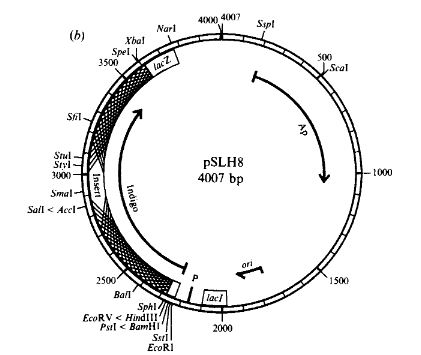
Unfortunately, the only plasmid that was still intact was labeled pSLH1. pSLH1 is described the paper “Construction of an insertional-inactivation cloning vector for Escherichia coli using a Rhodococcus gene for indigo production” as “The prototype insertional-inactivation cloning vector pSLH1… level of production appeared to be lower than that of other pigment-producing strains…cells produced only slight amounts of pigment even after several days incubation at room temperature.” According to my observations, this is accurate- it takes a while for the transformed bacteria to produce indigo. This seems to be because between the the indigo production gene and the promoter (an in-frame lacZ’a fragment upstream of the gene), there is a stop codon and two rare codons which theoretically prevent the gene from being expressed.
Deletion of stop codon
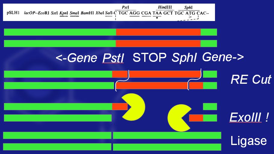
Hart and Woods went ahead and deleted the deleterious fragment of the gene by cutting out the undesirable DNA, chewing the ends of the DNA back with exonuclease III, and then blunt-end ligating the ends together. Amazingly, this deletion keeps everything in-frame, and produces more indigo than without the deletion. The process is shown in the image above. First, the gene is cut, then the exoIII blunts the ends, and finally they are re-ligated.
In theory, this is great, and it totally works. In practice, something was mislabeled or possibly only a mutated version made it to me 20 years later, because the sequence I got was not the sequence from the paper. It was pretty close, but definitely different. Lets compare:
Modern read -G TCG ACGG
From paper -C TGC AGGC GA
Bolded letters show the “wrong” codons for the cut recognition site (CTGCAG) for PstI. My hypothesis is that the new read is correct, and that the old read was flawed in one way or another. This is because the new read was duplicated exactly the same across 8 independent samples, and the old read was probably done once. The new reads were done on a modern sequencing machine, while the old read was done from radioactive sanger sequencing, which can be hard to interpret, leading to easily transposed letters in the sequence.
The authors may have gotten lucky with the enzyme as well. I was using a recombinant “HF” enzyme, which stands for high fidelity. This means that it has lower star/non-specific activity, reducing the chance it will make an improper cut. To give you an idea of how much more specific the HF version is, I took this snippet from the NEB website:
“The minimum number of units of PstI-HF required to produce star activity in the recommended NEBuffer 4 is (4000 units). The minimum number of units of PstI required to produce star activity in the recommended NEBuffer 3 is (120 units).The minimum number of units of PstI required to produce star activity in NEBuffer 4 is (8 units)”
So the short version is that the HF version is something like 20-500 times more specific. 20 years ago, the PstI may have been even less specific, and allowed for cuts like the one that was made. Or, somewhere along the line, a lossy polymerase copied the DNA wrong and my copy is mutated.
Either way, what actually seemed to happen was that the double-digest with PstI and SphI turned out to be a single-digest. If you look at the actual sequence:
CTTGCATGC
it would be cut like this:
CTTGCATG || C
then blunted to this:
CCTG C
and then ligated to this
CCTGC –> gene
Instead of increasing yield, this introduces a frame-shift mutation, which makes the gene totally useless since it is being translated out of frame. Transforming the DNA yielded ampicilin resistant colonies with no indigo production ability.
So that was a big waste of material. However, there is some good news! The price of DNA synthesis has dropped, and the length of DNA that can be purchased has increased! In these new and exciting times, the cost of synthesizing the gene is only about $200! So I think my next steps are to codon-optimize the gene for e. coli, add restriction sites, then to add a promoter to it and stick the whole thing into p2kb to share with people.
Some nice indigo-producers mixed in with not-nice ampR colonies
Last year I got an awesome grant to work on the bluegene project. Awesome grants are by definition, awesome. For those who don’t know, an awesome foundation grant is a no strings attached $1k grant. They are granted one a month by decision of the awesome foundation trustees, who each put up $100 towards the grant. As a result, are very flexible, community oriented, and can support all kinds of projects. In my case, the awesome grant allowed me to work on project bluegene.
Project blugene is a project to increase the yield of indigo from genetically modified e coli. The e coli harbors a plasmid that contains the sequence fpr a monoxygenase from rhodococcus. This enzyme acts on indole, turning it into indoxyl, which spontaneously turns into indigo in the presence of oxygen.
So what happened to the grant money? What has happened in bluegene? The answer is that a lot has been done, but not much has changed. Unlike mechanical or electrical engineering, bioengineering has a much slower and much more expensive turnaround time on prototypes. To make sweeping generalizations, a programming project will generate almost instantaneous feedback when run, and takes hours to iterate on, mostly for free. A pcb design might take a few (2-3) days to fabricate and test. A small mechanical prototype can be cranked out in a week, but feedback can be generated as it is built. Implicit in all these things are feedback tools built on hundreds of years of innovation and iteration, from compiler debug output, multimeters, and logic analyzers to micrometers, thread gauges and coordinate measuring machines.
Biology has none of this. Debugging is hard, and the parts are for all intents and purposes, invisible. Things are getting slightly better (cheap sequencing, qPCR), but its nowhere near the level of ease of a micrometer or o-scope yet. And with school in session and a 6 hour round trip commute to the lab, the amount of time I have put in is less than I want. The result is that the gene was modified, with the result of only disrupting and not improving the function of the gene. This was a result of trusting the sequence from the paper, instead of the more contemporary sequence from the plasmid I had. It was a stupid error, but it seemed straightforward at the time.
The approximate cost breakdown is :
$200 for restriction enzymes and exonuclease
$65 for a plasimid prep kit
$80 for ligase
$80 pcr/gel extraction kit
$80 error correcting pcr master mix
That comes out to $500 for one iteration, not including DNA sequencing, PCR primers, lab consumables like DNA stains, agarose, media, pipette tips, petri dishes, or microtubes. Doing the cutting, pasting, and testing is also incredibly time intensive and pretty boring. While it is theoretically exciting that your DNA is being copied thousands of times by amazing enzymes, it is not exciting to sit on a couch and wait for it. The waiting time and the cost make it expensive to iterate and improve designs.
However, there is a technical solution to the problem. The toolset I was using on the project was based in molecular biology, and fundamentally comes down to cutting, pasting, and copying pieces of DNA. At the time, it was a cheaper tool-set by maybe $200 compared to DNA synthesis. But that was a year or so ago.
In the last year the cost of 1kb+ (kilobases, not kilobytes) DNA synthesis has plummeted. There used to be extra costs associated with genes over 1kb in ligation and in wastage of the ends of the synthesis. Now, both life and IDT are offering cheap synthesis of genes in excess of 1kb. Life technologies offers up to 3kb and IDT oferers up to 2kb genes. IDT even offers MIXED BASES, allowing you to have random mutations in certain portions of your gene.
The price for the gene that I spent $500+ and many hours unsuccessfully modifying now only costs about $210 bucks, and I can have it in a few days instead of after a few weeks. That price and turn time are about the same price as a small quick-turned PCB. While the debug tools are not quite there yet, biological prototyping is really catching up to other engineering disciplines. Clearly the next move is to get the DNA synthesized, and try it out!
I was about to go through the thermal camera code today and comment and neaten things up, when my friend walked into the room. He had brought me a gift- a gift of bananas. He knows I like bananas, so he brought some to the dorms for me. We decided to make some coffee, so I put the bananas on my computer for later. These bananas led me down a long and exhausting rabbit hole by causing a very tricky bug. By the time I got back to my coding perch, I had somewhat forgotten about the bananas, which were long since consumed along with the coffee.
I made some modifications and hit the build button, and tired to upload the code, but it wouldn’t work. I found out that I was getting an error during the debug! The log read:
[builtin](2): Including file ‘C:\Program Files (x86)\Atmel\Atmel Toolchain\AVR Assembler\Native\2.1.39.232\avrassembler\Include\m328Pdef.inc’
C:\Users\alouie\Documents\Atmel Studio\6.1\ThermalApp2\ThermalApp2\ThermalApp2.asm(10): Including file ‘C:\Users\alouie\Desktop\m328Pdef.inc’
token too large, exceeds YYLMAX
I tried everything to fix the situation. I copied the code into a new project, and it it wouldn’t work, so I hadn’t messed up my build options. I tried getting a new version of the m328def.inc files, which turned out to be up to date. I tried commenting out the .inc file (since it looked like it was throwing the error), but I knew the .inc file was good because other projects would build. The one thing that did work was deleting all the code and just having a loop like:
main
rjmp main
When I did this, I copied the whole file into sublimetext as kind of a giant clipboard. This turned out to be really important to finding the bug. Now that I knew I could get blank code to build, I started adding things back into the code. I knew the bug had something to do with line size, or a missing “, but I couldn’t find anything out of the ordinary. Once I hit the main loop section of the code, the error became apparent.
There were thousands of space characters, all on one line.
The banana had landed on the space key, and typed out about 28 thousand spaces. Of all keys, that is the worst one it could have landed on. Infinite return lines, or a long string of characters is easy to catch, but whitespace is invisible in atmel studio. In sublime text it is wrapped, which fills up lines, and there is no new line number, so it is easy to see.
Last time I reported that I could take b/w “stills” with the thermal camera. This meant that the system would do this:
set up registers
get ambient sensor temperature
initiate i2c start
interrupt driven i2c read of registers
display a lit led if temperature>ambient
Unfortunately, this looked pretty lame, because it never updated. To fix this, I added a timer interrupt that interrupts every 100ms. It initiates the i2c transaction that reads the sensor values. 100ms was chosen because the camera updates at 10 fps, so a fresh frame is ready every 100ms. Doing this cuts down on time spent running i2c transactions, which produces a flicker free display. A timing diagram of the system would look like this:
0ms start i2c transaction
0-3.5ms read i2c data and output pixel data
3.5-100ms output pixel data
As you can see in the video, it can tell when my hand is hovering over the sensor, as well as what direction it is coming from. The clarity of how this is displayed should improve when I wire up all the LEDs.
The next steps of the process are to:
wire up the rest of the display such that the micro will not tank if the voltage drops
The thermal camera can now take B/W thermal stills! If the temperature is higher than ambient, the pixel lights up hot. Else, it stays dark. The rough steps in the code are:
start I2C get all pixels
while 1:
output pixels
Now all I need to do is add an interrupt that calls the I2C start every 100ms, which is as fast as the camera updates. This will start re-writing the image data and let the output be “live”!