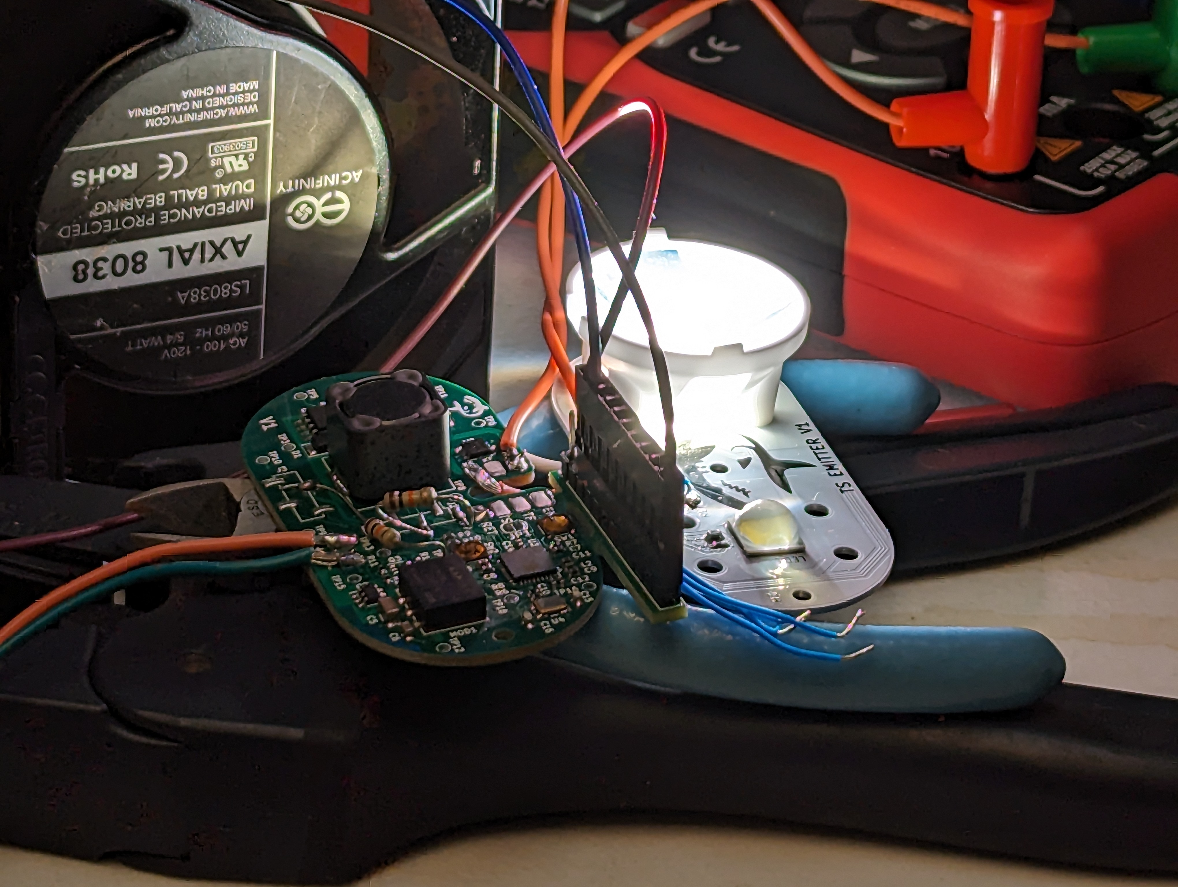
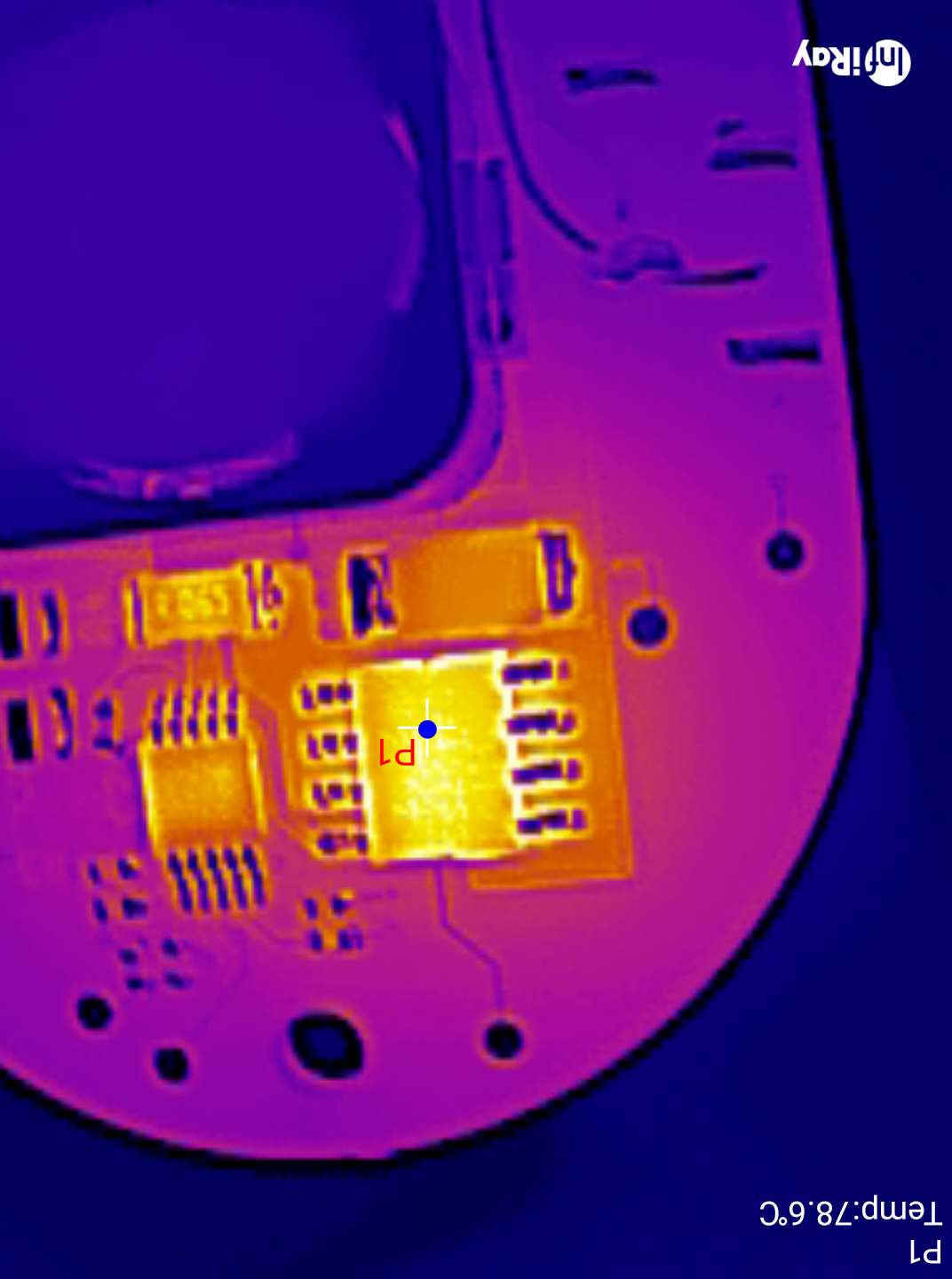
With the dive light parts in hand and assembled, it was time to test it out and fix all the inevitable mistakes. I expected this to go pretty well, and bringup for most low power functions was a breeze- however, at higher currents, this thing is a pretty good heater. This led to buying a fun tool – a thermal camera!
ESP32 bringup:

This was my first bare-chip-down ESP32 design, and it was actually pretty easy to do. I used the variant with internal flash to save room, so the only external components were a crystal + caps, some passives (R’s and C’s), and a switch for the RESET line, and a switch on the BOOT (gpio 9). However, there are two additional strapping pins (GPIO 0 and 2) that needed pulldowns. This was annoying since these pins were not pulled down on the pcb – some of them were pulled up, so the parts that did that needed to be removed, and the functionality of those circuits needs to be checked some other way.
I think in the future, it would make sense to avoid using the actual boot and reset buttons and use something like the ESP-PROG to toggle all the lines. Needing to push buttons to upload code is a drag!
I also consistently had issues soldering the QFN package the ESP comes in- I think this was due to too much paste on the center thermal pad. This causes the chip to float, and sometimes this causes one side of the chip (or a few pins) to lift. Next time I will reduce the amount of paste on the center pad to fix this, but I resolved it here by removing the chip, solder-wicking the thermal pad, and then re-soldering the part. Using low temp solder paste made this really easy.
LM3409 Driver bringup:
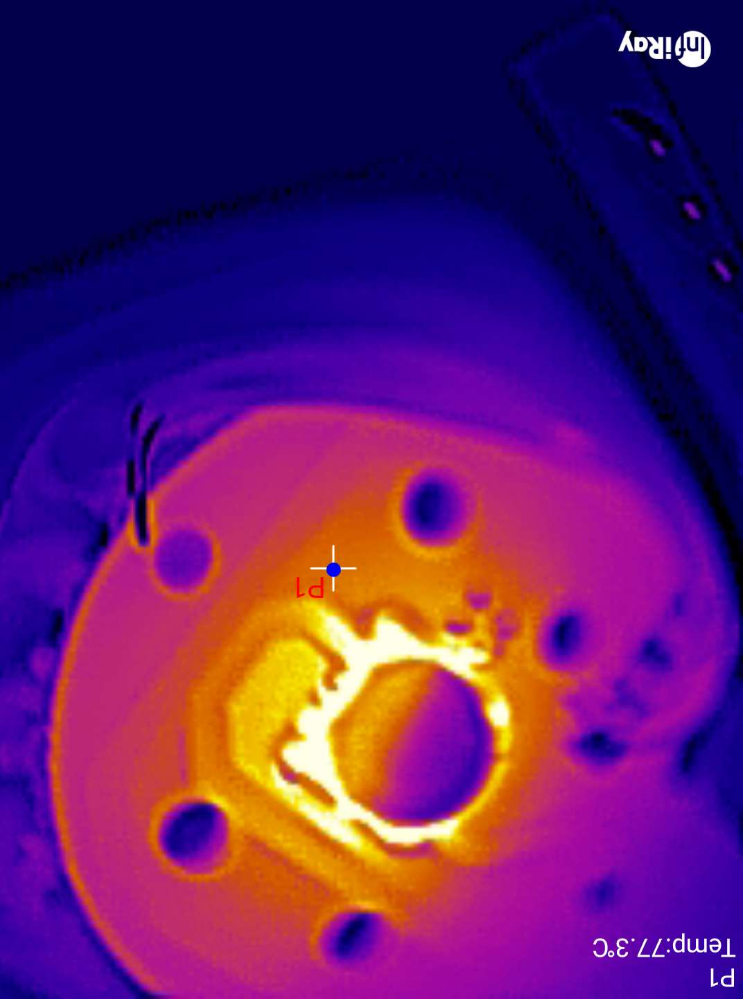
The LM3409 bringup went relatively well, but thermal issues started to crop up pretty much immediately. There are some surprising deficiencies in the layout and parts that I will be modifying for future revisions. The thermal camera really helped to visualize the issues quickly, and given the number of thermal/power projects I have worked on recently I am sure I will get to use it quite a bit.
PFET Gate Charge
One hair raising issue was that during bringup, the board started to smoke. This is almost always a bad sign. In my original estimation, this was caused by the buck PFET getting hot due to having a high gate charge. The odd thing is that the freewheel diode also got really hot, and stayed hot even if the led was very dim.
A very basic thermal investigation with two thermocouples showed that the FET was getting hotter than the diode, at least initially. However, I did smoke several diodes in the process.
Reducing the gate charge did appear to solve the problem, and there was even a note in the datasheet (that I glossed over) about keeping the gate charge below ~30nC. Having a high gate charge is problematic for two reasons- it keeps the FET in a high RDS region for longer during switching, and it requires more power from the gate driver on the LED controller, which also heats up. However, this was not the real problem.
Overheating and Limp Mode:
Gate charge was not the entire story. With the FET replaced with a lower gate charge/higher RDSon model, there was still an issue! With the LED aggressively cooled (to allow it to live), the device would still go into some kind of limp mode after a few minutes of operation at high currents (3.6A avg, 12V, about 42W).
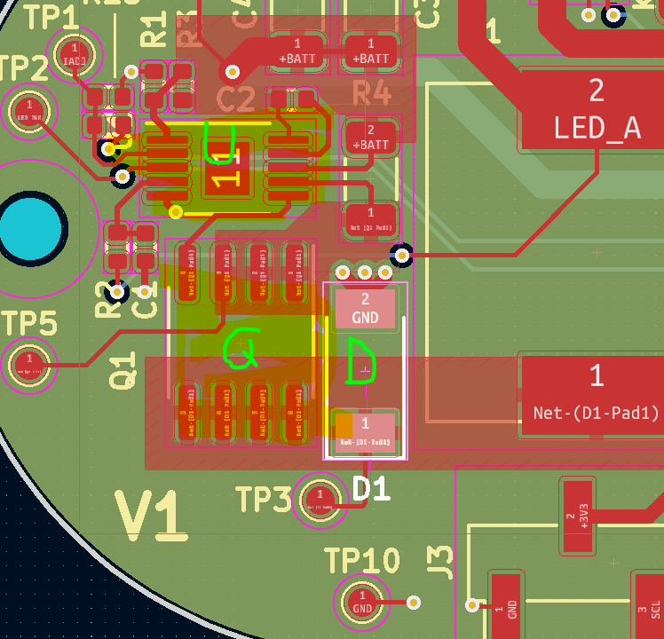
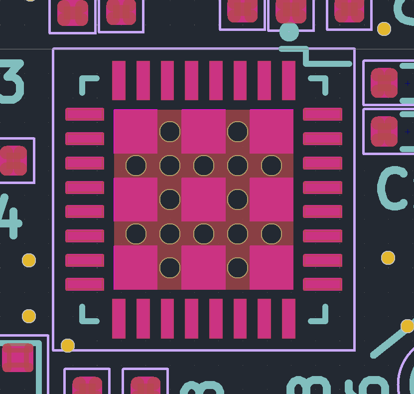
This seems to be due to the driver itself overheating, which is due to my poor thermal design. The driver is marked U in the layout above- this is supposed to have a thermal pad connected with vias to ground. I omitted the vias, essentially insulating the chip- no good.
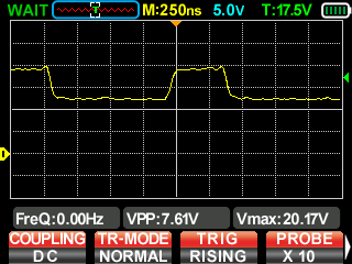
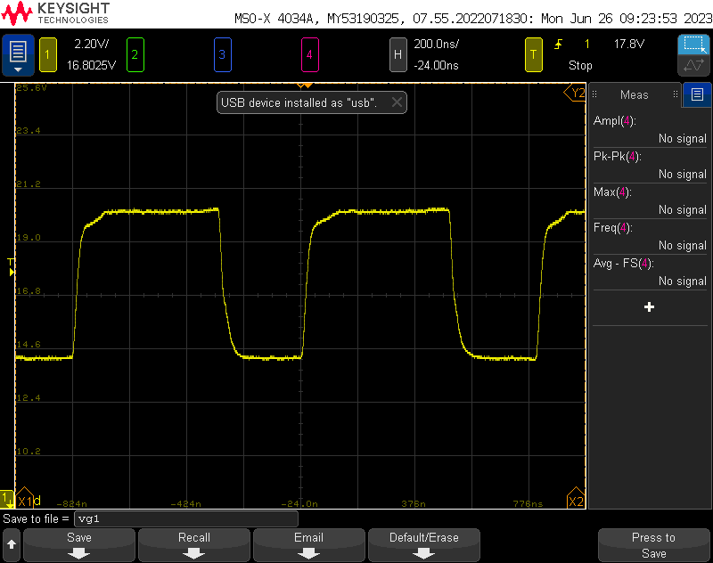
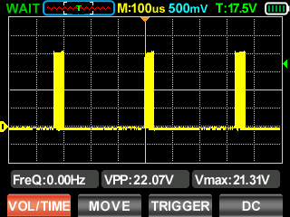
Second, at high currents, the regulator needs to switch frequently to keep in regulation. Estimating from the gate voltage above (in terms of time), and assuming maximum 1A gate drive currents, I estimate that the total switching time is at least 100nS with a period of about 1375nS. The average voltage is about 16.5V, so 16.5V*1A*D = ~1.2W. This would probably be easy do dissipate if I hadn’t insulated the chip. Reducing gate charge helped reduce the power this chip was dissipating, but it was not the root cause.
To make things worse, I didn’t add much copper to dissipate heat on the FET, and at least half the copper is on the side of the driver, which actually makes things worse (its easier to for the FET to heat the driver). Adding some vias to a large plane on the back, and increasing the area on the front will increase the area the heat can easily dissipate from.
The reason the diode gets hot is because usually, the diode only free wheels for a short amount of time- when the FET is off. When the driver goes into limp mode, it has to dissipate all the energy stored in the inductor, many times a second.
So the full story is- this driver will self destruct if the driver overheats and goes into hiccup mode. Better thermal design (and eventually cooling it in the ocean) will probably improve the situation, by preventing driver overheating.
A wiser choice of package for the FET might also help dump heat to the PCB, which will be important when this is running in an enclosure. Convection won’t be an option then, and all the heat will need to go into the case.
Efficiency + Thermals:
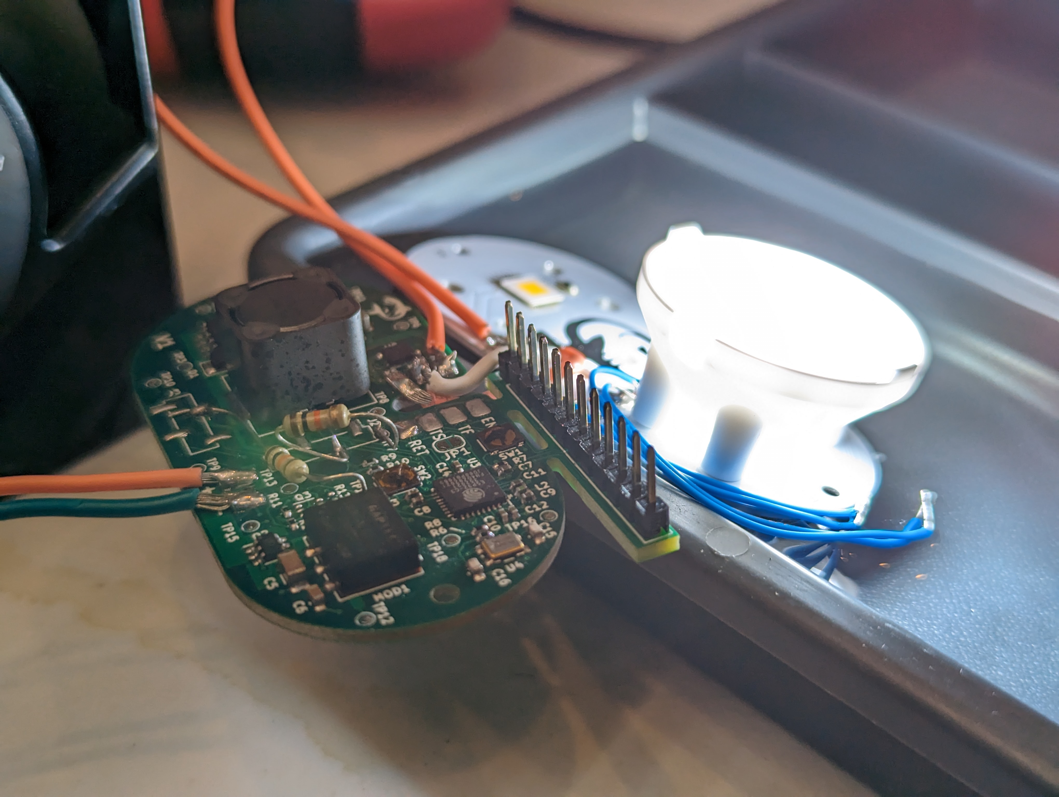
With the driver sorted, the next thing to do was to smoke test the lamps at high currents. This went reasonably well, with only one LED burning out. As you can see above, the XHP70.3 required a heat sink and passive water cooling in order to prevent burnout. Given that its running at about 42W and only ~25% of the energy is turning into light, this is a 32W heater in a 70x70mm footprint.
This is going to be very hard to keep cool, even with the die almost being in contact with the seawater. The good news is at lower settings (around 2A) I should still get a very respectable 3000 lm out of the LED- more than the sola light!
Overall efficiency from power supply to LED was acceptable- in the mid 90’s for lower currents up to about 1400mA, and in the high 80’s above that. while that might seem like poor efficiency, this takes into account relatively long lead wires to and from the pcb, the multimeter, etc, so I actually expect it to improve in the final product, especially once the thermal design is improved.
Conclusion:
This PCB needs to be re-routed with thermal concerns and strapping pins in mind, but overall, it works! This iteration has given me a lot of confidence that the final design will do what I want it to do. I’m also really excited to keep playing with the thermal camera. It gives me a lot more information than the sizzling finger test, and it lets me dig into the context and sequence of the heating.
