I recently found out my sola 2000 torch is torched- water got in and corroded the connectors. while it might be technically salvageable, I used this as an excuse to start another project- a canister dive light. I love my sola light, but the battery does not quite last two dives, especially at full blast. This means I need to bring two lights, two chargers, and two lights, and that is a little inconvenient. It also means I spend a lot of time futzing around underwater going from low to high power mode. This is surprisingly annoying, especially since I have to use two hands to switch modes.
Armed with google, hubris, and kicad I set out to design my own dive light.
Design Goals:
The goal is to build a dive light, with spot and flood modes, just like the sola lights. I want a burn time of at least 3 hours at a reasonable brightness- this is well over two recreational dives. I want it to be a canister light so I can run it full blast for the whole dive, temperature permitting. And I want it to be about as bright as the sola lights. And small. And I want a pony to go with it (kidding).
Optics and LED choices
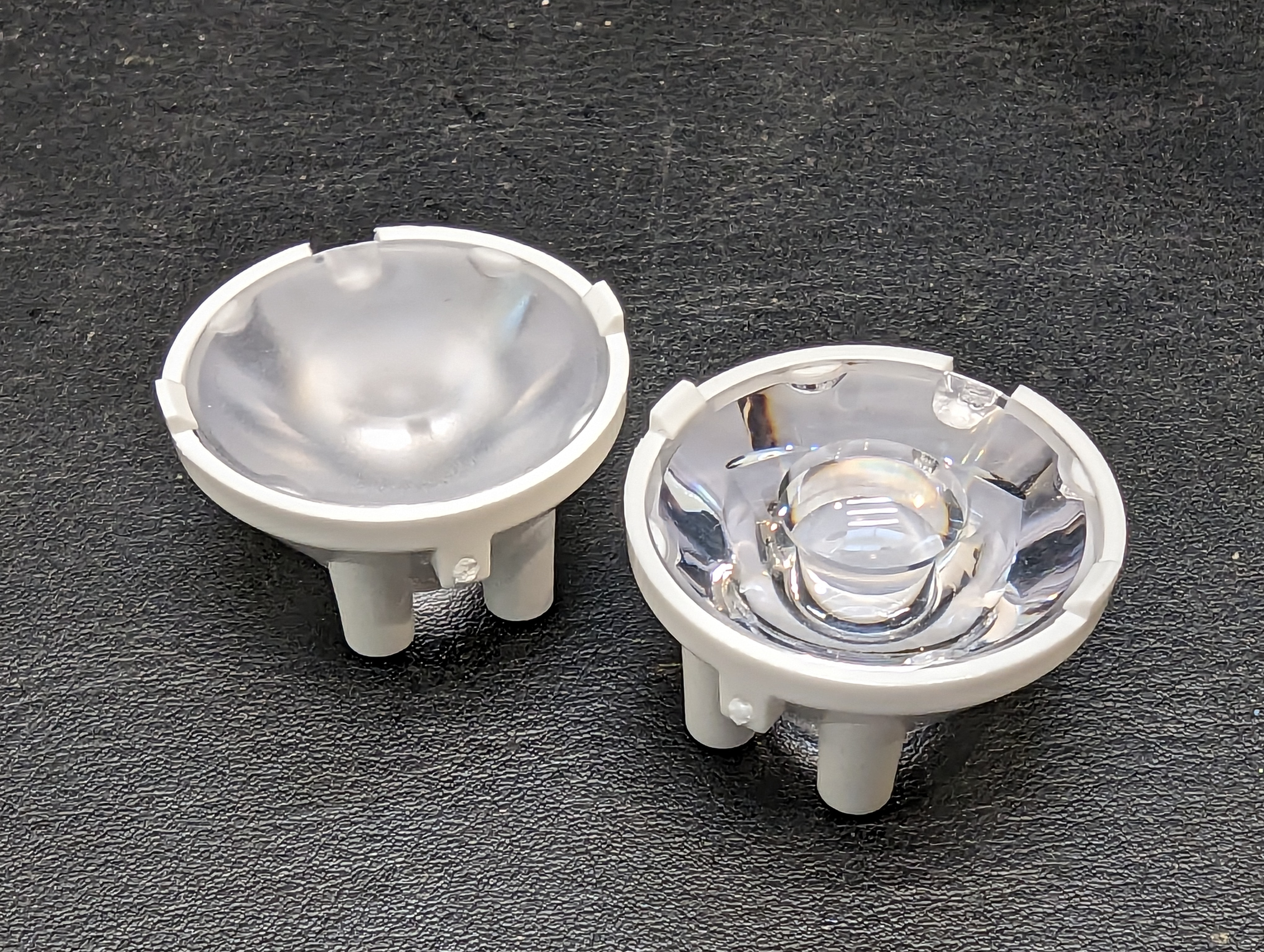
There are a lot of constraints on this project, starting with thermal and optical considerations. There are only so many off the shelf optics, and without much in the way of a mechanical prototyping department, I want to minimize iterations. The simplest way to do this was with single LEDs and off the shelf optics. Carclo has not only an impressive array of parts to buy, but they also have charts/images to go with the optics with different base LEDs.
The problem with single LEDS is that the efficiency of the LED suffers at high outputs. This creates a lot of heat. Hopefully I can use the ocean as a heatsink. CREE seems to make hands-down the best high output LEDS, and after some careful considerations of what is available in low quantities, I decided on one XP50.3 and one XP70.3 LED. Two XP70.3’s would be better, but the beam pattern on the spot light would be too wide, since I can only get the XP70.3 with a dome lens.
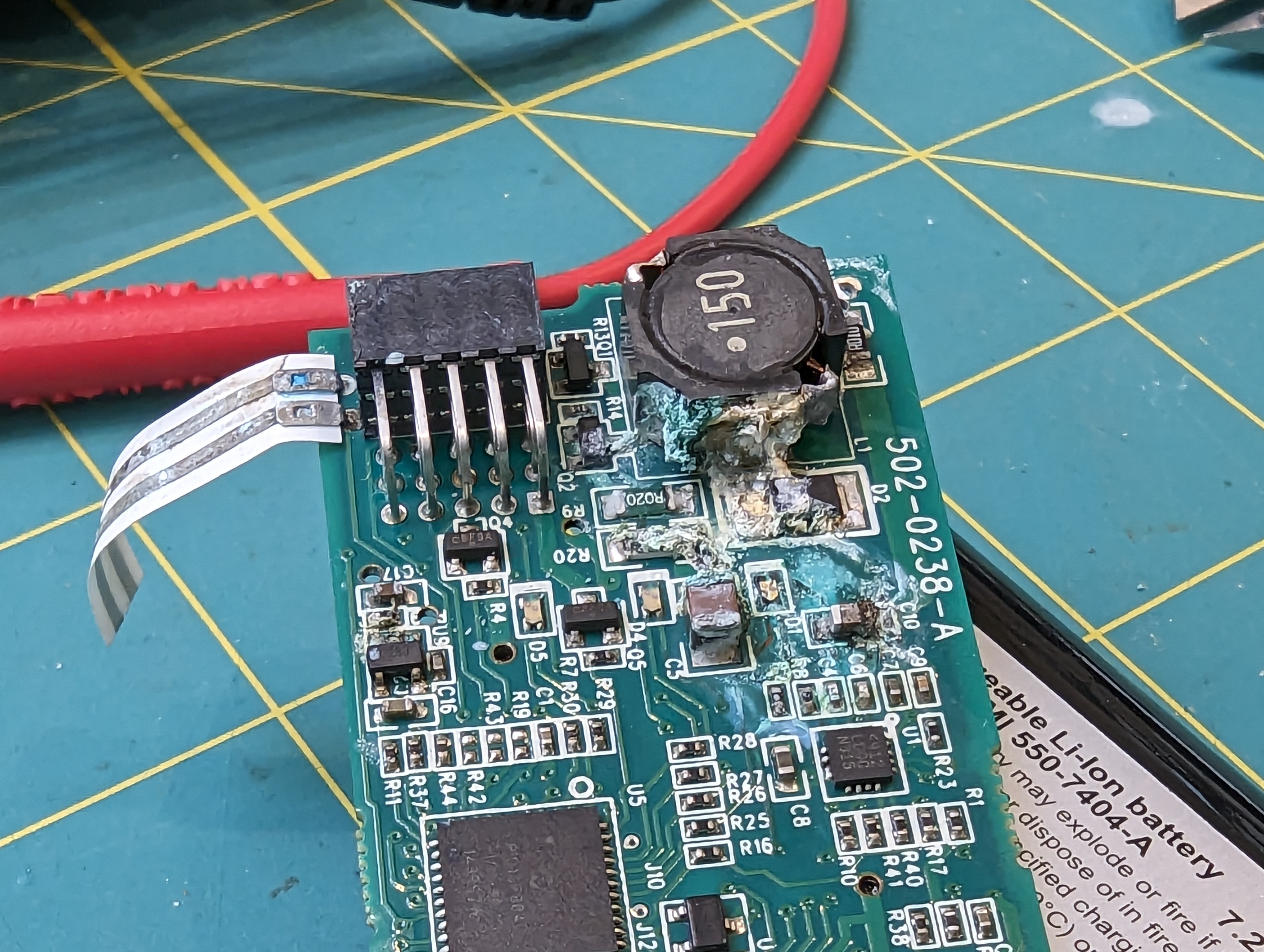
Driver

Next up was the driver. It seems pretty useless to have spot and flood lighting on at the same time, and as you can see, the PCB does not have a lot of room on it for another big driver and inductor. Instead, I intend to share the high-side LED driver across both LEDs by low-side switching them. The header on top is for programming, and as a breakout for interesting pins.
Microcontroller Selection
I begrudgingly picked the ESP32 as my microcontroller. It seems like a shame to have and not use a ton of the peripherals on there, but its cheap (compared to an attiny), small (but still has a lot of pins), and in stock (unlike the atsamd series). This requires a 3v3 regulator, and due to size and laziness constraints I opted for an integrated DC-DC module. These are awesome, cheap, and easy to assemble, which is nice because I already had a lot of 0402 parts.
Emitter (LED) Board
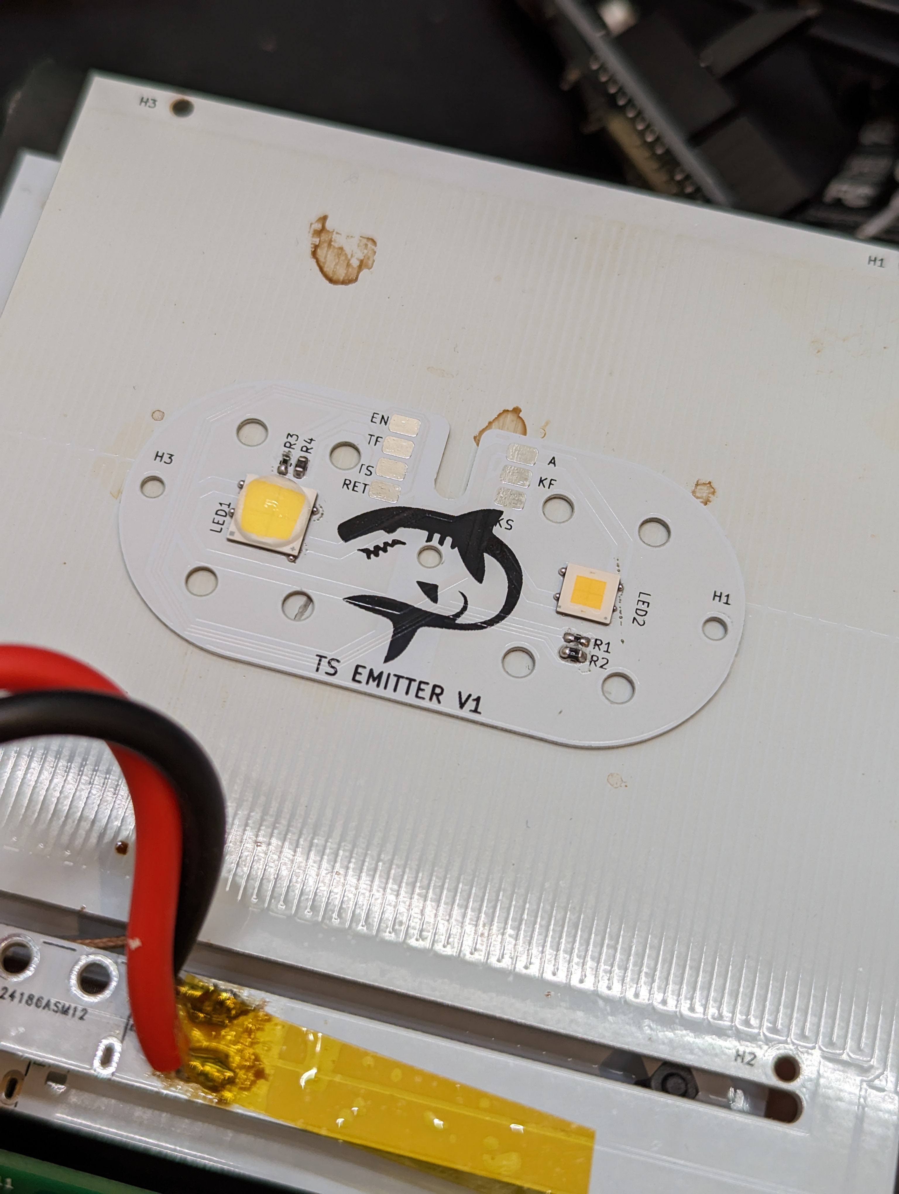
The emitter board is aluminum, for better heat conductivity. At full blast, this will need to dissipate ~30W! In addition to LEDS, there are a couple thermistors for temperature measurements, placed near the LEDs. Given that each LED is a multi-watt heater that could probably melt itself off the board (with low temp solder), it seems prudent to monitor temperatures.
next up: firing up the retina blaster!
