I ended up with a day to work on my spin coater in between a few other projects. Originally, I wanted to make a nice spin coater but because I am basing the design on a random ESC and motor that I bought 5 years ago, I decided the rest of the build would come from the junk bin as well- at least that would be fast.
One component I don’t often use (aka have in the junk bins) are “fast” analog light sensors, like the kind you would use for a tachometer. However, I do have a lot of LEDs, and I managed to find one single op amp part in my junk bin, and so I figured I could either spend a day designing a pcb that would come in 2 weeks, or spend one day hacking together a tach.
My goal was to get a digital signal out of the system, where one rising or falling edge corresponds to one revolution of the motor. I want to run this motor from about 5-10k RPM, which means each revolution is 100 uS. Detecting something every 100uS is pretty slow in circuit land, so I was not worried about the speed of the electronics.
LED as a photodiode
I know that an LED can be used as a tiny tiny current source, and that there are two common ways to amplify it- with a transistor or with an opamp. I tried a transistor to start, since I knew I had some 3904s stashed away from an old project. However, this did not give me enough gain- the signal was only about 100-200mV with a bright light shining into the LED. I didn’t try the darlington pair, because later I found out I did have three (3) dual op amps in my junk bin.
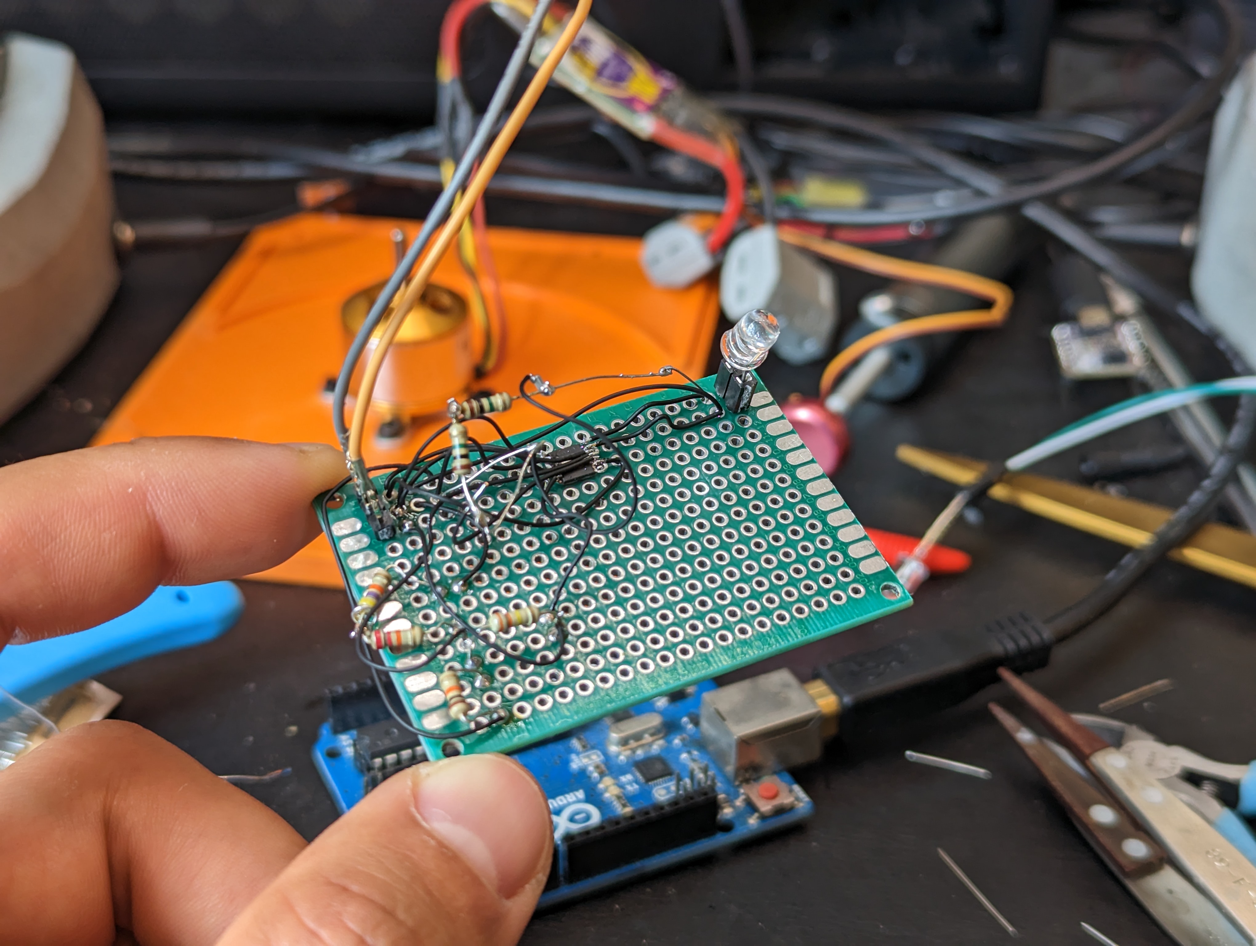
I ordered three ALM2403QPWPQ1’s for some reason in 2021. I have no idea why, but I was pleased to find out that I had an op amp on hand. Fortunately, these are .65 mm pitch parts- that makes a big difference compared to .5 mm pitch parts for unaided hand soldering, deadbug style (note to self: buy microscope).
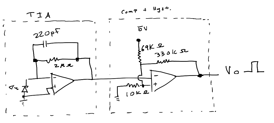
With these dual op amps, I could actually get everything I needed out of a single chip. The first stage is a transimpedance amplifier with the photodiode as a current source. This takes the current generated by the photodiode and turns it into a voltage. In theory it should be pretty linear with incident light, but I didn’t test this.
Since I have no idea where my LEDs came from (junk bin leds!) I just stuck in the values from the make article linked above (by Forrest Mims). This seemed to work well enough, but and testing showed that increasing the feedback resistor to 2Mohms gave me suitable gain, with an output around 1.5-2V. This signal gets fed into a comparator block later, so the actual value is not too critical- just that the signal has a wide enough swing.
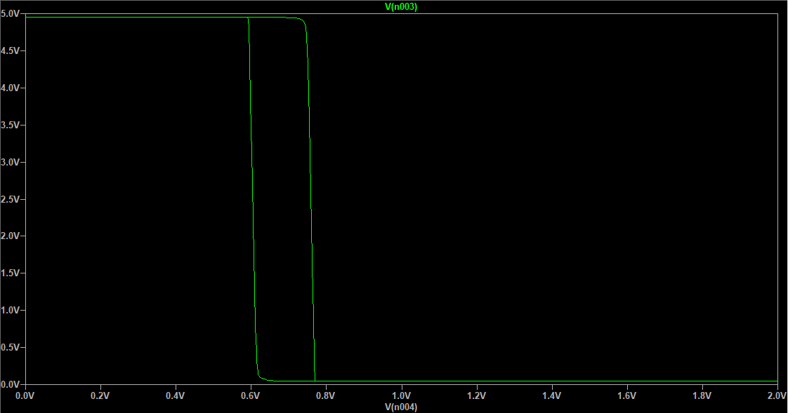
The comparator block is built out of the second op amp, resistors I had lying around, careful soldering, and this app note on adding hysteresis a comparator. I had to tweak the values to the resistors values I could make, but after some simulation I got a suitable result. Here you can see the .2 V of hysteresis in a plot of input vs output voltage.
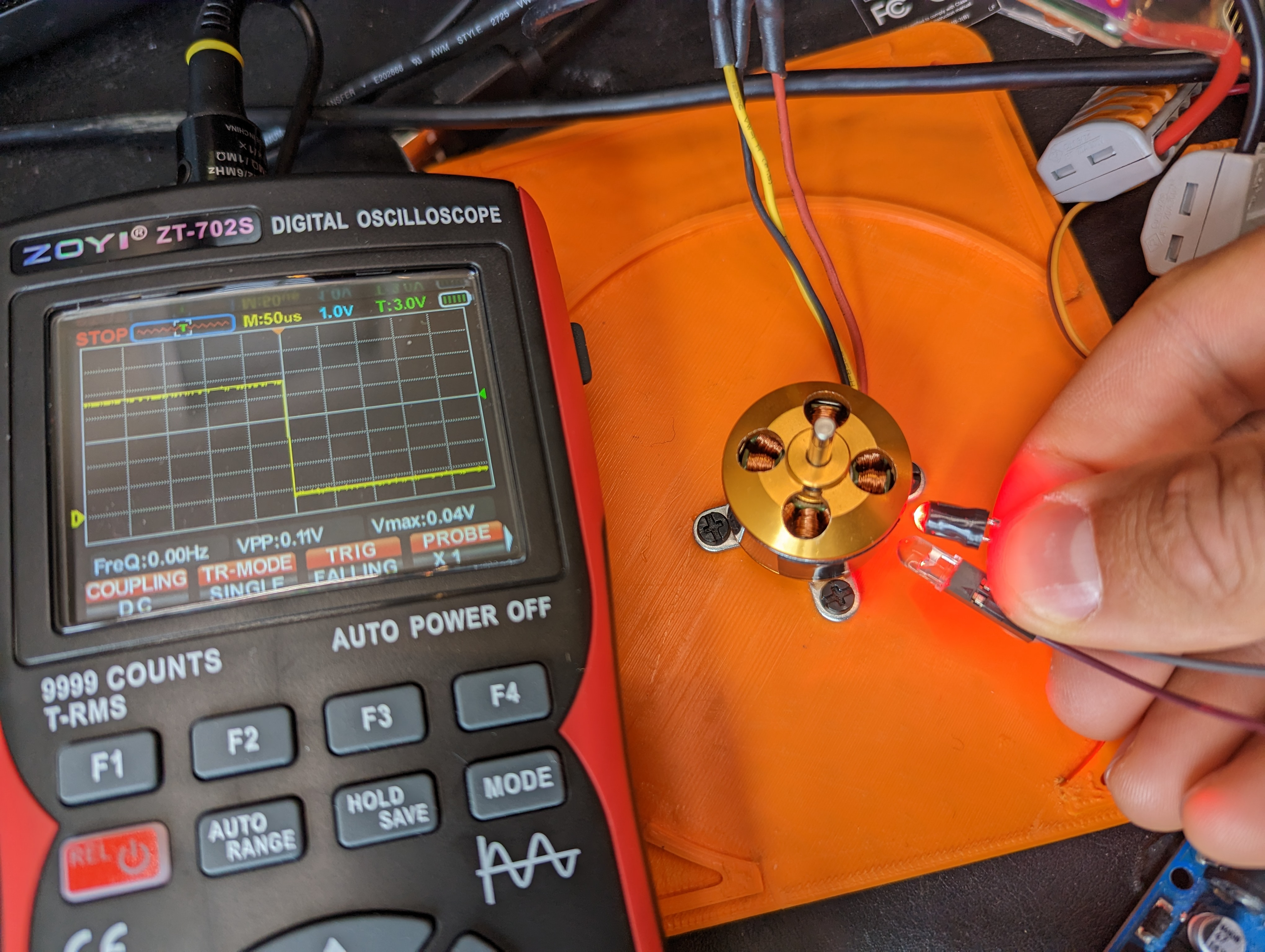
As you can see in the title photo, this produces a nice clean edge as the motor body (shiny) transitions to the tape (black, not shiny) that I stuck on it. Now its back to the mechanical drawing board to make a platformt to test/write software, and time to order a VERY simple PCB for when my questionable soldering starts to fall apart.
New Tool: ZOYI ZT-702S

A one new tool that made this way easier was the ZOYI ZT-702S. I bought this to augment my basic multimeter. I was skeptical of the oscilliscope feature after suffering through quite a few substandard scopes.
It turns out to be a total delight to use, and it is great for simple stuff like this where I want to look at some quickly changing value or to measure a rise time or to see if a signal is ok. It physically much easier than breaking out my big scope (because the big scope is VERY big). The portability also seems awesome- I have done all kinds of nonsense where I need to measure a sensor in the field and a multimeter is okay, but a very basic scope would be way better. This thing rules! It can even take screenshots, and the menus are straightforward.
My main gripe so far is that the auto range button exists- since its next to the hold button, I press it by accident sometimes and this resets my measurements and puts the scope in AC mode, instead of restarting the triggered data.
As a basic multimeter it also does fine, and the continuity beeper is very fast, and the probes are pretty nice. I am excited to add this to the toolbox!
