Knowing your PO2 goes a long way towards making it safer to go deeper with an oxygen rebreather. If you want to go pure O2, it can be used to monitor how purged the loop is, and if you want to go a little deeper it can basically turn an O2 rig into a sort of mixed gas rebreather (or a full mixed gas rebreather with proper diluent addition).
In order to conveniently know my PO2, I have purchased O2 sensors. Having built in temperature compensation and having reliable manufacturing seems like a big plus vs fabricating, assembling, testing, QCing and calibrating my own.
For my first iteration I have started with just two cells. A third would be easy to add if this works out.
Layout and Logic
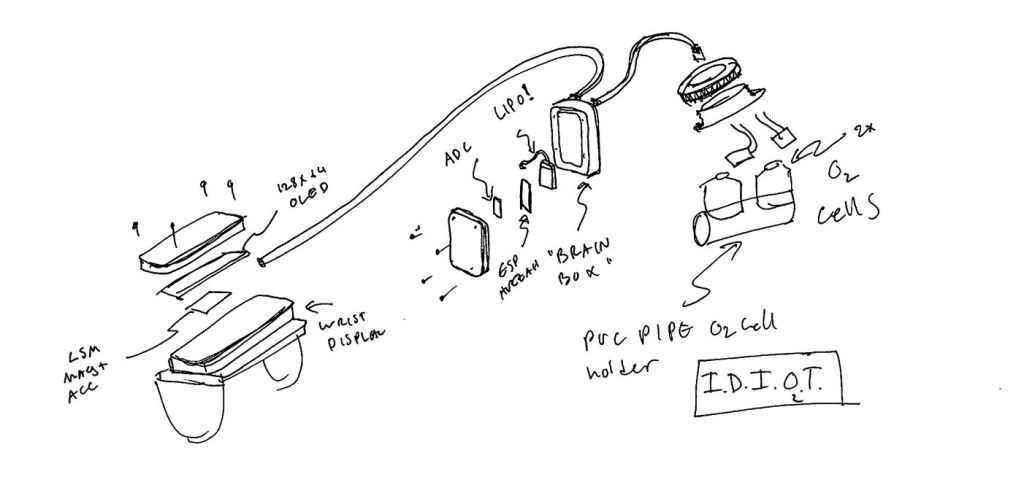
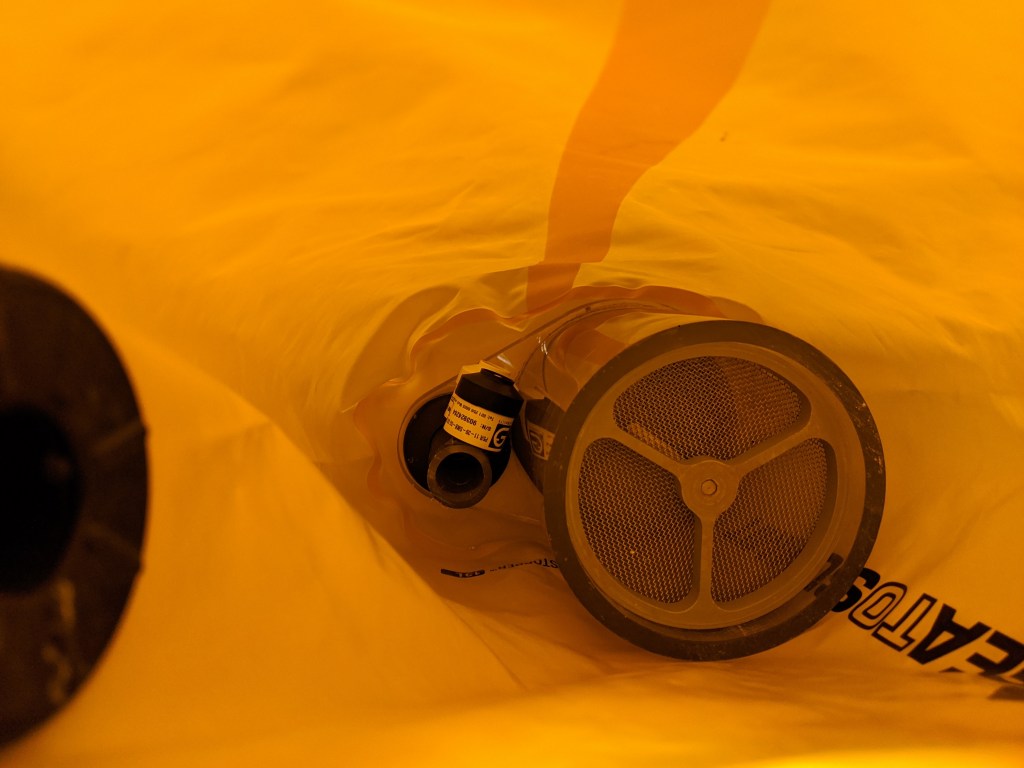
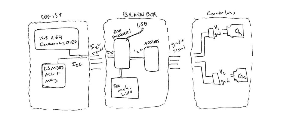
The electronics are going to be split into three parts- the cells/stuff in the counterlung, an electronics box, and a display. I decided that the only things in the counterlung should be the sensors themselves and a connector.
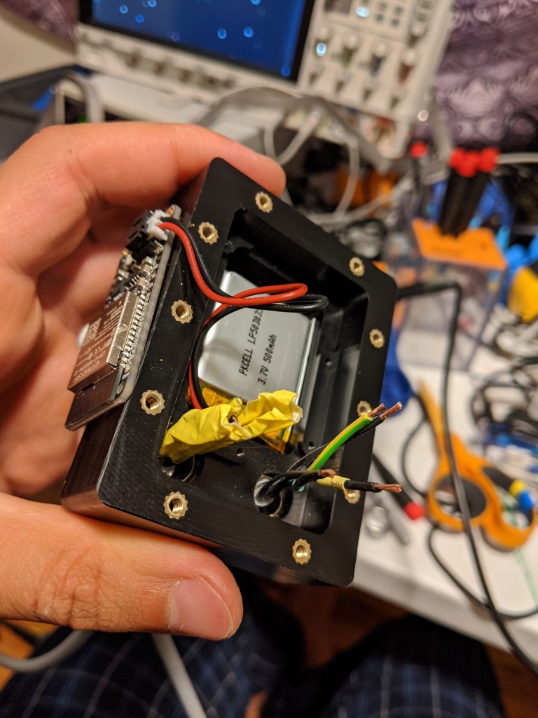
The “Electronics Box” will house the brains of the operation (an ESP32), and the battery. Batteries and other flammables will be kept outside of the oxygen rich environment of the rebreather, for obvious reasons. In the unlikely event of the battery shorting to the cells, hopefully the high impedance of the cells will limit resistive heating or fire. In the future, a USB port with a cap will be wired in for charging.
This box has been tested to ~80 FSW with just the cord grips+cord installed, and it passed without noticeable leaking. The cord grips are MSM-M SKINTOP connectors. They don’t seem like the should work, and yet they do. Mcmaster sells these as “submersible cord grips”. N.B. they make a face seal with the enclosure, and do not require a gland like an SAE o ring boss (ORB) fitting.
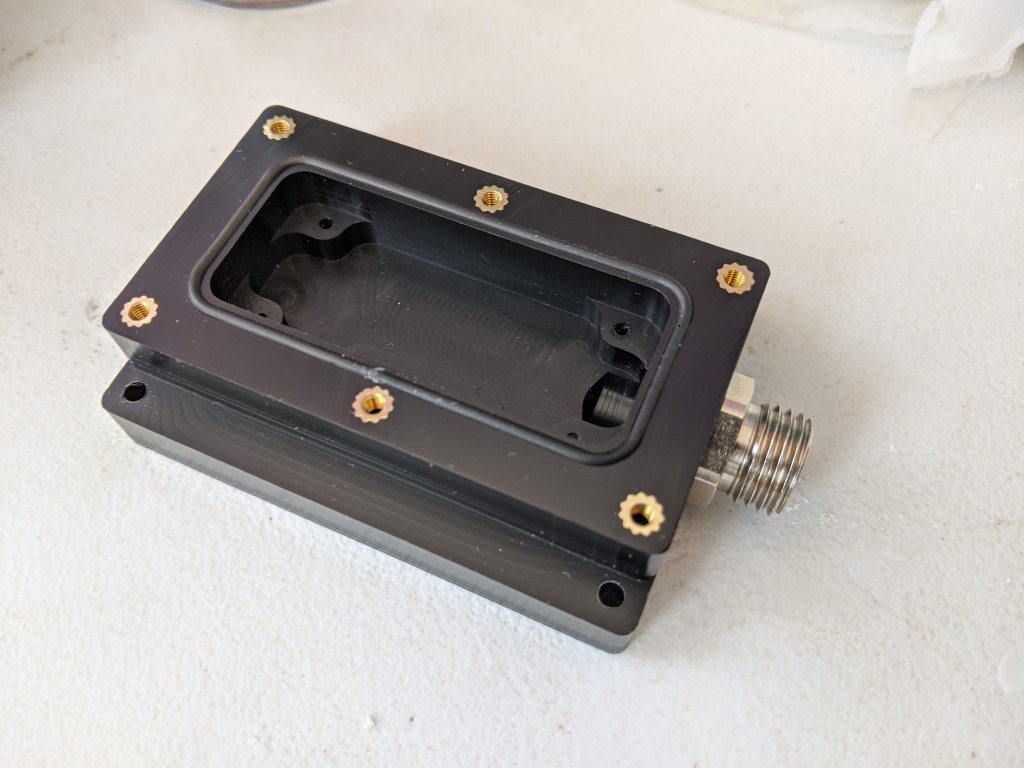
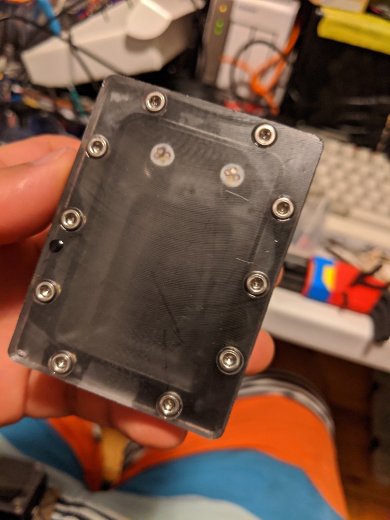
The main oring seal is a 1.5mm oring made from cord stock and superglued at the ends. You can see the join just above the middle heat set insert in this photo. Surprisingly this does not seem to create any significant leak paths, although there is always a slight possibility that I will have to eat my words on that someday.
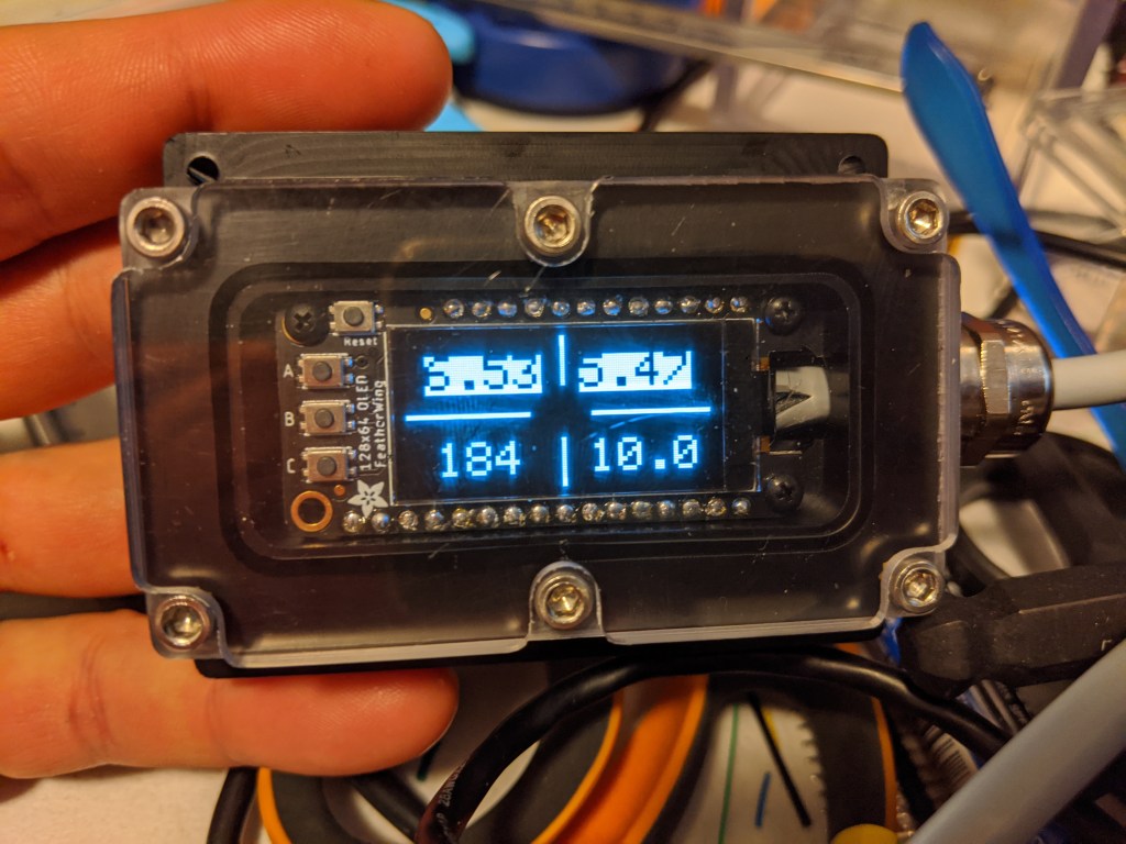
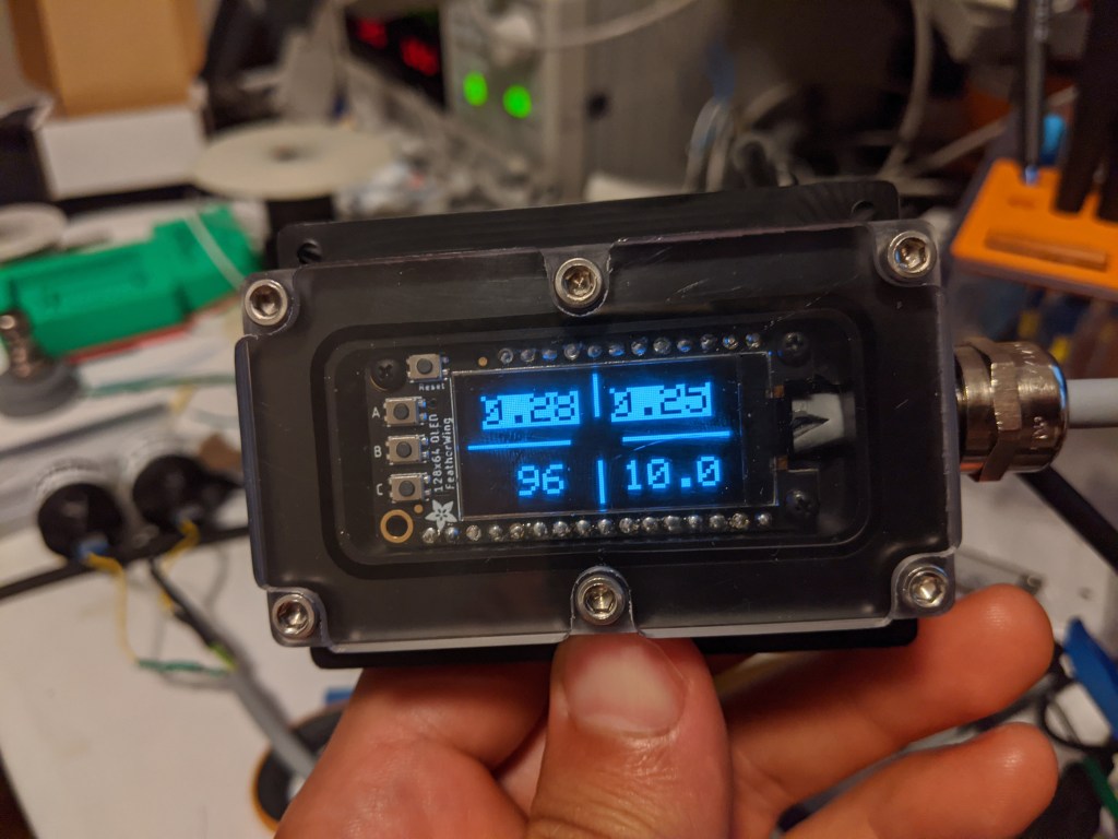
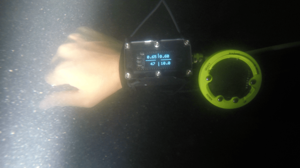
The display will be upgraded to a HUD at some point, but for now it will be wrist mounted. It displays two PO2 cell readings, a compass heading, and (in the future) the depth. As you can see in the photo, the top row is “highlighted” to show a problem- the cells are disconnected and are reading a very high PO2.
The Electronics
Reading an off the shelf galvanic O2 cell is dead easy, since the temperature compensation and shunt resistor are built in. However, the output voltage is fairly low, and so it should not be fed directly into the ADC of a typical micro. It is possible to read such a voltage (~20mV), but it wastes a good portion of the resolution of the ADC.
For example, the maximum output expected is 2V (representing a PO2 of 2). With a 5v ADC, we are only ever using 2/3 of the range of the ADC, which effectively limits our resolution of PO2s to 2/3 the resolution of the ADC.
Since these signals are also not amplified or buffered in any way, it seems good to keep them away from the mcu. I have resolved to put them on an I2C DAC with an internal gain stage, which will let me both maximize resolution and keep the signal wires for the cells short. To this end, I used an ADS1015 breakout from adafruit.
Since it was on hand, I also threw in an LSM303 to use as an electronic compass. Since the compass has no “inertia” it has kind of jumpy readings, but doing some smoothing should help to get it to be a little less jittery. I could also try some compensation for nearby electronics, but they seem to have little effect. The LSM accelerometer/magnetometer lives in the wrist piece, although I did consider mounting it in the “head”, which would show you body heading, but not necessarily what you are looking at.
The display is the 128×64 OLED featherwing. Its easy to integrate, and it is fairly compact in terms of “extra space” for unused headers/buttons.
Testing
I headed to the mystical mystic lake to do some testing. The combination of near zero visibility to start with and a haze of sediment/algae/stuff I don’t want to think about made for a more-or-less night dive like conditions, even with a light, during the day. However, the little O2 cell reader and compass seemed to behave relatively well. Most importantly the firmware did not crash, and no water seemed to get in. Cant wait to test it somewhere actually fun!

One thought on “Integrated Dive Information and Oxygen Transmitter (I.D.I.O.T)”