More Leak Testing + Data Capture

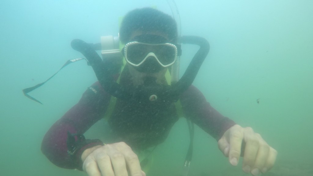
Gas, for the most part, should stay inside of a closed circuit rebreather- that’s sort of the entire point. So leak testing is very important- important enough to automate to get really good data. Unlike reading a gauge with your eyes, automated data capture, if done right, can make it easier to capture a lot of data, and it takes out errors caused by a person interpreting an analog gauge face. I also wanted to add temperature measurement, as that seemed likely to cause pressure deviation, even to the point that the pressure in the volume under test seemed to go up.

Test Setup

Test setup: 15V power supply, arduino , max31850, dwyer 605-20

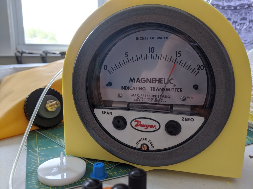
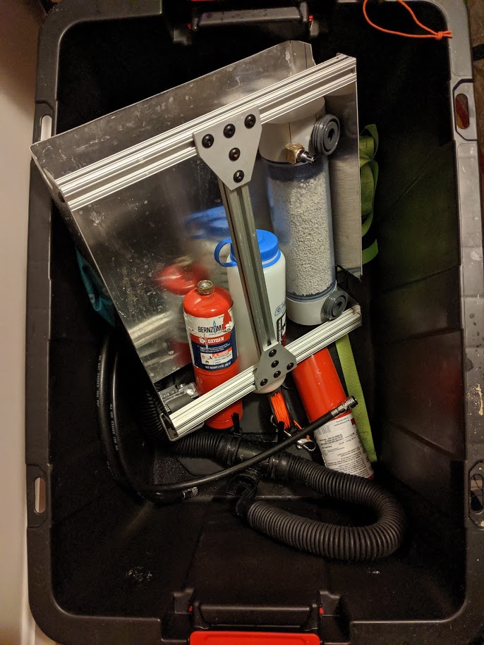
Automated data logging is nice since it is much less tedious and usually allows for a lot more data and more data sources to be reliably sampled. In this case, I didn’t have a lot of bench space to dedicate to this, and the sampling rate was low, and I wanted to use stuff I already owned. So I ended up using an arduino as the “data collector”, a MAX31850 as the temperature sensor, and a the dwyer 605-20 as the pressure sensor.

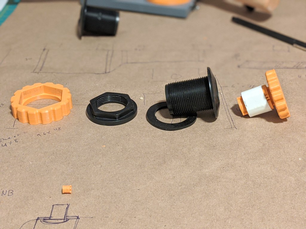
I think the most annoying part of this is the pressure sensor- its just not really meant for this application, as its powered at a somewhat high voltage (10-35 VDC) and outputs 4-20 mA (current, not voltage) across the span of 0-20″ of water. While measuring the current is possible, and even possible to automate with some of my gear, it would take up a good amount of space, and it not really necessary.

Schematic from pressure transducer datasheet. Y leg connects to arduino ground, X leg connects to Analog 0

Of course, since the pressure sensor basically becomes a current source, it is possible to stick a resistor in there to create a voltage drop. The resistor can’t be too big (requiring too much current) and making it too small will mean there is not a large enough voltage drop. I managed to find a 200 ohm resistor in my junk pile, which turned out to work well:

Output Voltage:
.02 A * 200 ohms = 4 V
.004A * 200 ohms = .8 V
Max Power Dissipation:
200 ohms * (.02 A)^2 = .08 W

According to the datasheet, 200 ohms and running at 15 V would work fine for the pressure sensor, so I had to pull out a power supply. It seems weird that I could turn the voltage up to 35V and still have the pressure sensor work fine and output the same voltage, but I guess that is the magic of it being a current source.

Sample Data

Ah, tasty data

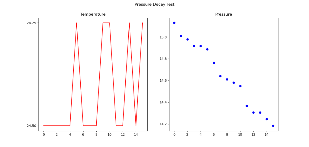
Here we have 15 minutes of data- it was being recorded every 1 minute. As you can see, the pressure dropped about 1 inch of water over that time period, with little change in temperature. Since I have a differential pressure gauge, changes in barometric pressure should be zeroed out. So we can finally observe a leak! Given a rough volume of 13 liters (stated volume of drybag), and a nominal room temperature, it comes out to about 30 ml of gas lost over 15 minutes.

How Good is Good Enough?

People say that if you can measure it, you can change it. That might be true, but making something completely leak proof is more or less impossible- just keep looking and you can find a leak at some pressure or with some penetrant (like helium, a very small gas!). It’s important to know when something is good enough!

EN-14143 is a European standard for rebreathers, so lets look there for some leak rate and pressure information.

5.6.5 Exhaust valve
The apparatus shall have an exhaust valve, operated automatically by excess gas in the breathing circuit.
The exhaust valve shall prevent the pressure in the breathing circuit exceeding 40 mbar.
Testing shall be done in accordance with 6.5.3.1 after the test according to 6.5.3.2.
The operation of the exhaust valve shall not be degraded or leaking after being subjected to
a) a constant flow of 300 l min-1 for a period of 1 min;
b) a static negative pressure of 80 mbar for a period of 10 s (when in the wetted condition).
The leakage of the exhaust valve (when in the wetted condition) shall not exceed 0,5 ml (STP) min-1 when
tested with a negative pressure of 7 mbar for at least one minute.

from EN-14143 which I found somewhere online. Emphasis mine

According to this, the maximum pressure the device should experience is 40mbar across the counterlung. Anything greater should be vented by the overpressure valve. Additionally, it looks like .5ml/min of leakage at 7mbar (2.8″ water) is permitted. At a higher pressure of 15″ water, it seems like the leak rate is about 2ml/min. This is encouraging since this is the leak rate for the whole system, at a much higher pressure. However, it still merits a test around 3″ of water.

Another analysis would be to consider gas supply vs leakage, since there is not a lot of gas in this rebreather. Assuming a worst case leak rate of 2ml/min, for a 30 minute dive an additional 60ml of oxygen would be lost. As a person requires somewhere around 500ml-1000ml of oxygen per minute, this seems like a very small amount to loose- less than a minute of dive time.

Overall I am surprised and pleased with the leak rate, and with an automated setup, it should be easy to take a look at this whenever I want, or across different devices and iterations. Fortunately, it looks like I might not need to do much to reduce leak rate.

Counterlung Pressure Decay Testing

The counterlung is a pretty important part of a rebreather- for the design I am pursuing, it is doubly so- not only is it a single counterlung, providing both buoyancy and breathing gas, but it houses the scrubber canister. In addition to housing the scrubber, gas addition and gas dump are located on the counterlung.

Obviously, water should be kept out of the counterlung, and gas should be prevented from escaping the counterlung. There are some qualitative tests that can be done to tell if something is leaking- spraying it with soapy water to see bubbles, or holding the counterlung underwater can show if gas is coming out. Or, the counterlung could be filled with water and I could look for water leaking out. However, both of these tests require careful observation and it is not always easy to see where the leak is coming from- for examples bubbles or water can leak from one area, get trapped, and appear to come from somewhere else. Its also hard to quantify how bad a small leak is. For a rebreather, there should be no bubbles at all.

For a more sensitive and quantitative assessment of leakage, a pressure decay test can be used. This is easier than measuring extremely low gas flow rates. The concept and execution are simple- fill the counterlung up to a pressure, and observe it the pressure goes down. This gives you an idea of how leaky something is, and its used on everything from respirator masks to space craft parts. The leak decay is much better than pressing the bag by hand, since the test can be preformed at the operating pressure of the bag. Ideally, its never more than ~20″ of water, from roughly the mask of the user to the bottom of the counterlung. Not coincidentally, 16″ of water is 40 millibar, and is the EN-14143 specification for the cracking pressure of the overpressure valve.

Magnahelic 650-20 Indicating transmitter, in the background is the schrader valve for adding gas and in the foreground is the gas tap plug that goes to the transmitter

Here is the pressure gauge I’m using. Its a transmitting gauge, which means at some point I’ll hook it up to some kind of data acquisition device to get some time series data, but for the moment I am just reading off the gauge face. It is also extremely sensitive- each division is .018 PSI or ~125 pascals.

counterlung in the vertical position- metal bar is on the bottom

To give an idea of the sensitivity of the gauge, I was pleased and surprised that it can indicate a change in pressure when the sealing bar on the bottom loads the walls of the bag (by lifting the bar with my hand, it takes the weight off the fabric structure). This is important because hopefully the leak is very small and very slow.

Issues with data collection

There are a few issues with collecting good data. One is that temperature plays a huge role in pressure, and so a room full of windows and a struggling AC (temperature fluctuation) and storms rolling in and out (air pressure fluctuation), its hard to measure a small pressure differential. I have actually seen the pressure go up, which is the opposite of what you would expect in a leak decay test.

To resolve this, I might do one of two things- either test during a calm night when the solar effects and weather effects are minimized, or add a temperature sensor and automatic data logging to try to correct for the temperature swings.

Another annoying detail is that my hose is a hair too small, and sometimes it starts to slip off the very delicate barbs (which occasionally snap). So I may need to characterize the leak of these barb connections to make sure I don’t accidentally characterize that leak as the leak of my system, if the leak is significantly large.

Preliminary Results

Two important things were done- first, qualitative submersion test to look for gross leaks. A few were identified around the sealing bar, which is by far the sketchiest seal. The leak always occurred right in the middle of the bar, where the seam from the bag was. Replacing the hand-tightened nuts with nyloc nuts and cranking down with a socket solved this issue.

I also ran a few leak decay tests, which turned up the aforementioned pressure problems. However, the pressure did hold for a few hours at only seemingly a loss of a few inches of water, which seems acceptable but I think further testing will be important to do.

3D Printed Arbor with Flexures

Bulkhead parts are in black

I recently had an issue with tightening bulkhead connectors. Since one side is round, its hard to really crank down on the nut that seals the flange! Grabbing the tiny, round flange just does not provide enough torque, no matter what you do. I am using these on a new counterlung design, so my goal was to make some small tools for assembling or breaking down the rebreather, but they needed to be hand-operated. While I did consider drilling holes in the flange and making a pin spanner that would be annoying since that is a sealing surface and because I would need to modify off she shelf parts whenever I got them. So I decided to build a arbor to grip the ID of the part.

Interstate - 1-1/2" Face Diam x 4" OAL Expanding Lathe Arbor ...
Typical expanding arbor, this one is from MSC

Typically an arbor is pretty simple- a wedge is screwed into a slitted block, and the block (in this case a cylinder) expands. This is pretty simple, and is a wonderful one piece construction. However, if you tried to print this it would be unlikely to work because of the huge stress concentrator at the root of the cut, and because you are creating a torque that is pulling right where the weak layer lines of the print would have to be!

Flexures are cool

single-extrusion-width flexure for parallel motion

My solution was to use single-extrusion-width flexures instead. A flexure is more or less a skinny piece of material that is bendy and stretchy…but on purpose. Because the material is thin, the maximum compressive and tension forces on the material stay small, even when the material is bent. Consider a piece of polycarb bent to make a face shield vs a sheet of bulletproof glass. If you bend one, it will spring back to being flat, while the other one will snap in half!

Mechanisms: Couplings | Hackaday
photo from hackaday

Another important note about flexures is that they can be very rigid in some directions, but flexible in others. That is how flexure motor couplings work- they are rigid in rotation, but flexible in other directions, as you can see. And since they (should) operate in the fully elastic region of the materials stress, they should also operate more or less forever, with no maintenance. This is highly desirable compared to multi-part assemblies.

However, flexures tend to be long compared to the amount of motion they can produce. A good rule of thumb is the length of the flexure (including total length of a zig zag) will be 10-20x the length you can expect it to move.

I had already done some experimentation with single-extrusion width flexures for a small parallel motion flexure, so I knew they worked. I had not tried to make a zig-zag of them, but I knew in theory the slicer would slice them and that they would be extremely flexible.

Photo of flexure

Here you can see the folds of the zig-zag flexure. To increase the amount of friction, I glued a piece of 1/32″ EPDM to the outside with superglue. Superglue seems to have ok bonding properties with superglue, as long as it is glued to something rigid. I could probably peel the EPDM off of the mandrel if I wanted, and in previous tests the EPDM has failed, not the superglue (CA glue). One thing to note is that some of the zig-zags are actually stuck together by stringing on the 3d printer- this is really annoying, and this design would benefit from better retraction settings, or more space between lines.

Expander wedges shown in cross section

Here you can see how it works- two cones are pulled together, which acts on a conical surface in the arbor core. This pushes the wedges outward, and into the ID of the part. This is achieved with a heat-set M3 insert on one side, and a long m3 bolt that goes through the whole assembly. While it would be possible to have just one wedge, I thought that two would be better since it would prevent twisting the flexures and create an expanding cylinder shape instead of an expanding cone shape.

Another critical feature seen here are the fins on the cones that go into matching slots in the flexure. These prevent the nut from spinning freely, and it also allows transmission of torque from the handwheel to the arbor, once the wedges are locked in place rotationally.

The orange handles let you really crank down!

Here it is in use. the large diameter of the bottom wedge is for gripping- it is about the same size as the grip for the nut, and by using these two the nut can be tightened about as tightly as I could want.

Notes for successful flexure printing:

-make the width of the flexure the same width as your nozzle/whatever width your printer thinks it is printing

-flexure bending axis will be paralell to z axis for this technique. I could imagine a way to make a flexure on the build plate but that’s different than this technique

-try to convince your slicer to prioritize outside “skin” layers, including the flexure.

-Explicitly tell the slicer not to put the z-seam on the flexure. While flexures are bendy, the z seam in theory/in practice is thinner and weaker, and putting it on a flexure is a good way to snap it. A few seams here and there are ok

-Attempt some kind of strain relief where the flexure goes into the part-put a biiiig radius on the flexure before that point. since we are relying on a single width of filament to bond to the rest of the shell here, adding a radius here probably wont help since even the smallest printable radius is much much stiffer than a single wall thickness.

What I would do differently/what went wrong

The flexure I made is pretty aggressive in terms of width between folds. I could probably go down to fewer folds since the wedges dont need to move very far. This would give me more clearance between lines, which would help with the stringing issue Or I could even go down to just two wedges, which would give me a lot of room for flexures and could even give me some extra surface area.

Additionally, the angle of the wedges is a little narrower than some previous prints. This makes them tend to get stuck, as less of the restoring force of the flexures is pushing them up and back out of the cone of the flexure. Its only about a difference of 8 degrees included angle, but it is significant. This makes it a little fiddly to get the flexure out of the hole once it has been set. this could be improved by reducing friction between the printed surfaces, but it seems simpler to make it work right off the printer. It would be distracting if you were servicing something using the tool.

I will also probably change to some kind of hand-operable and fully captured screw. as it is, it requires an additional screw (allen key) to actuate the clamp. While that is ok, it would be very convenient to have a clamp that did not require a small, easily corroded tool, and it would be nice if the screw couldn’t fall out.

Oxygen Rebreather Dive Notes

Diving in Rockport MA

At this point this rebreather has been dived “wet” four times and it seems like a good time to make some notes on how it preforms. It certainly seems adequate-to-usable as an underwater breathing device, and as of the latest dive, I have even achieved a semblance of neutral buoyancy.

Dive Procedure

Building the unit up in Acadia ME

This is not a definitive “How to dive an O2 rebreather” manual. This is how I dive my scary prototype rebreather, usually alone, and unsupervised. I have no formal training and you shouldn’t use this as a basis for any kind of diving. That said, here is what I do to dive this thing:

The first step is to assemble the unit, including packing the scrubber. The scrubber should be filled with an appropriate amount of sorb appropriate for the dive (or more). As previously discussed, its about 4″ per cylinder of oxygen, for this given scrubber. The sorb should be shaken to allow to settle, and then the screen and spinner (see drawings) should be screwed on tight. At the end of this step, the oxygen should very slowly and very carefully be turned on, but not injected into the system yet.

The second step is a 3 minute pre-breathe. The goal of the pre breathe is to ensure that all systems, such as the MAV and regulator, are operational, and to warm up the scrubber. After putting on a dive mask, suck all the air out of the couterlungs and exhale it through the nose into the atmosphere. I exhale completely through the nose to empty the lungs, then start to fill the counterlungs and inhale. This ensures that there is minimal nitrogen in the system. Having too much nitrogen could cause a loss of consciousness if the mix goes hypoxic (hilariously unlikely with an O2 rebreather). Excess nitrogen could also allow nitrogen loading (leading to the bends). At the end of the pre-breathe, have a buddy or use a mirror to check the canister for condensation and for warmth. Condensation and warmth indicate that the CO2 scrubbing reaction is proceeding in the absorbent.

The third step is a bubble check. Divers should descend to 2-3 feet under the water and check each other (or use a mirror) to check for bubbles coming out of the unit- there should not be any. Bubbles coming from the unit call for an immediate abort- its not a rebreather anymore, its open circuit!

If the bubble check is negative for bubbles, the dive can proceed for up to 10 minutes (or other gas/scrubber limits). It is recommended to terminate the dive after 10 minutes since there is no convenient way to see how much gas is left (no SPG). This does not take into account chronic oxygen exposure toxicity of O2 at depth, but it is difficult to run up the O2 clock in only 10 minutes.

Once back on the surface, the DSV should be switched to the surface position and the diver can come off the loop.

Buoyancy

Buoyancy has been a challenge with this unit, but only because I am improperly weighted, since I only have one 10lb weight. The unit itself is about neutral to negatively buoyant in fresh water, and I am about neutral to negative in seawater (even with a partially inflated lungs). This leaves the wetsuit and a few liters of air to be balanced out by the weights- way less than 10lbs.

On open circuit, this additional weight can be balanced with a sac of air that the diver can fill and empty (a buoyancy control device). The remaining net small amount of positive or negative buoyancy is trimmed out by modulating breathing. Deep breaths and spending more time with more lung volume increases buoyancy, and the opposite decreases it.

With a rebreather, this is completely useless, since breathing out simply moves the gas to the counterlungs, which are still attached to the body. So the whole loop volume is what needs to be trimmed against the rest of net buoyancy of the diver, which, in this case, is very negative with 10lbs of weight.

However, it is still less than the volume of the counterlungs, so it is possible (as seen above) to achieve neutral buoyancy!

Trim

Trim has not been a big issue so far. Folding up my legs moves my center of mass close to the center of buoyancy, so I don’t have much trouble staying horizontal in a nice streamlined position. This might need more investigation, since I have not dived it in particularly calm water yet, and most of my time has been spent swimming, which helps keep a good trim.

Attitude and Work of Breathing

Work of breathing (WOB) is a big figure of merit for rebreather design. Work of breathing depends on counterlung (CL) position, and for any given rebreather the CL position changes as the diver moves around. In particular, pitching and rolling change the pressure of the lungs vs the counterlungs. I don’t have a way of measuring WOB, but it has been breathable through 90 degree rolls to either side, and about 30 degrees of pitching up. Pitching down tends to result in incurable mask squeeze, since the nose essentially makes the mask the lowest connected air volume. It is much more comfortable to avoid that, unless you really want to look at something in a deep hole. On another note (often echoed by rebreather divers), I have not had any issues with dry mouth or feeling “thirsty” during my dives, since the air is quite warm and humid when breathed- even in the chilly waters of the northeast.

Ergonomics

A couple easy, but substantial improvements could be made to the harness. It is very inconvenient to put on, involving an intricate dance of bending over and weaving the harness behind your back, while balancing the unit on your shoulders. Bolting it to a backplate or having seprate waist and hip connections (maybe even a chest strap) would make it much easier to don, and easier to tighten to prevent it from floating around underwater.

Additionally, it would be helpful to be able to clip off the MAV so that it lives somewhere on the users chest, enabling either hand to find and use it.

On the bright side, the hoses are fairly non-intrusive when diving, even though they are somewhat long, and even thought the unit is wide, it does not impede any movements to the front of the body, which is where the arms usually are while diving.

Cleaning and Storage

The unit is pretty small, and since most parts are plastic andhave no moving parts, it doesn’t require a huge production for cleaning. Everything just goes into the storage bin, gets rinsed, and then is set in the storage bin to dry. The two exceptions are the MAV and the Oxygen valve- the MAV gets soaked, and the oxygen valve gets soaked, while worked open and closed. These soaks happen with hoses installed, since I want to prevent the inside surfaces from getting salt/salt crystals inside of them.

Final Thoughts

This thing is pretty darn fun, and not as sketchy as I imagined it would be. It really does let you get a lot closer to fish and animals. I’d love to take it somewhere shallow and calm and clear, like blue heron bridge or crash boat beach, or a nice warm lake somewhere.