Smooth is Fast: G3 continuous curves for better 3D prints

The future is weird. This morning, I used my timeshare supercomputer subscription to (somehow) guess how write a plugin for a piece of modeling software I don’t own (you are welcome, autodesk). This little piece of code solves a problem that people have been aware of since the beginning of design, but that is hard to put your finger on. To put it less literally, I vibe coded a g3 curvature-continuous sketch fillet tool for fusion. You can get it here. If you care to know more about the problem, or if this table edge bothers you and you don’t know why, read on:

Curve Continuity

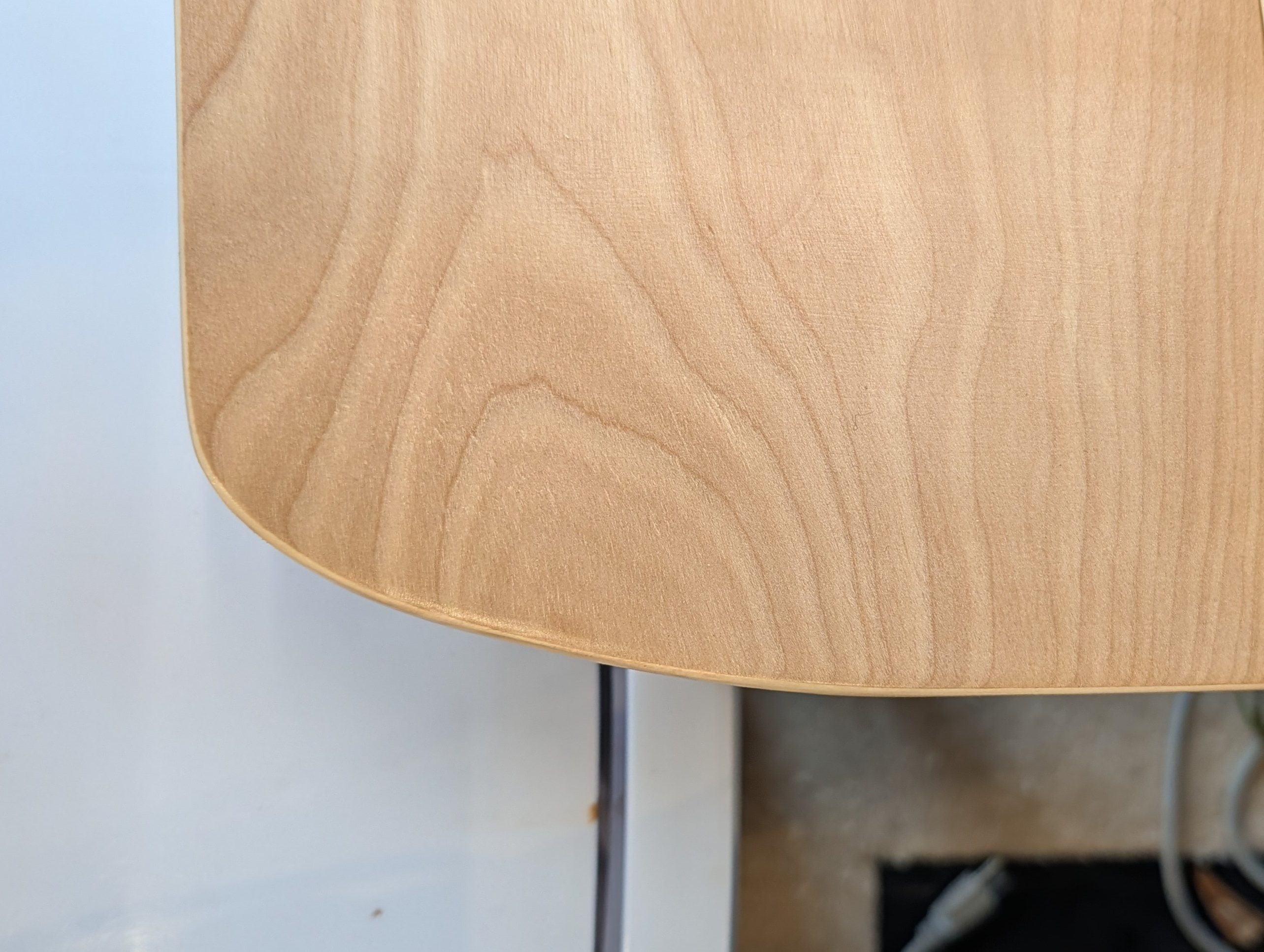
The edge of the table above is (supposed to be) made of two lines coming into an ellipse. Even though the lines are tangent to the ellipse (at east to the best of my ability), they look kind of strange. That is because an ellipse (or more commonly a circular arc) has curvature, and a line does not. So even for a tangent line going into a circular radius, there is a discontinuity.

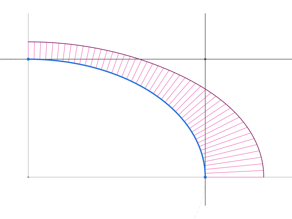
Here is an image of what’s going on – the transition is from the line (no curvature) to the ellipse, which does have curvature. That jump is something that you can see and feel. The little lines are called a curvature comb, and the length is related to the curvature where it touches down, and they comb lives on the “outside” of the curve.

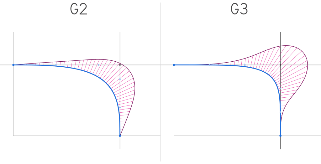
The fix is to use a G2 or G3 continuous curve. Note that both combs now start at zero curvature and ramp up. The difference is that a G2 will have a constant initial “velocity” (first derivative) of the curvature, while a G3 curve accelerates that change over time. So a G3 is smoother.

How this helps my 3D prints, and other things

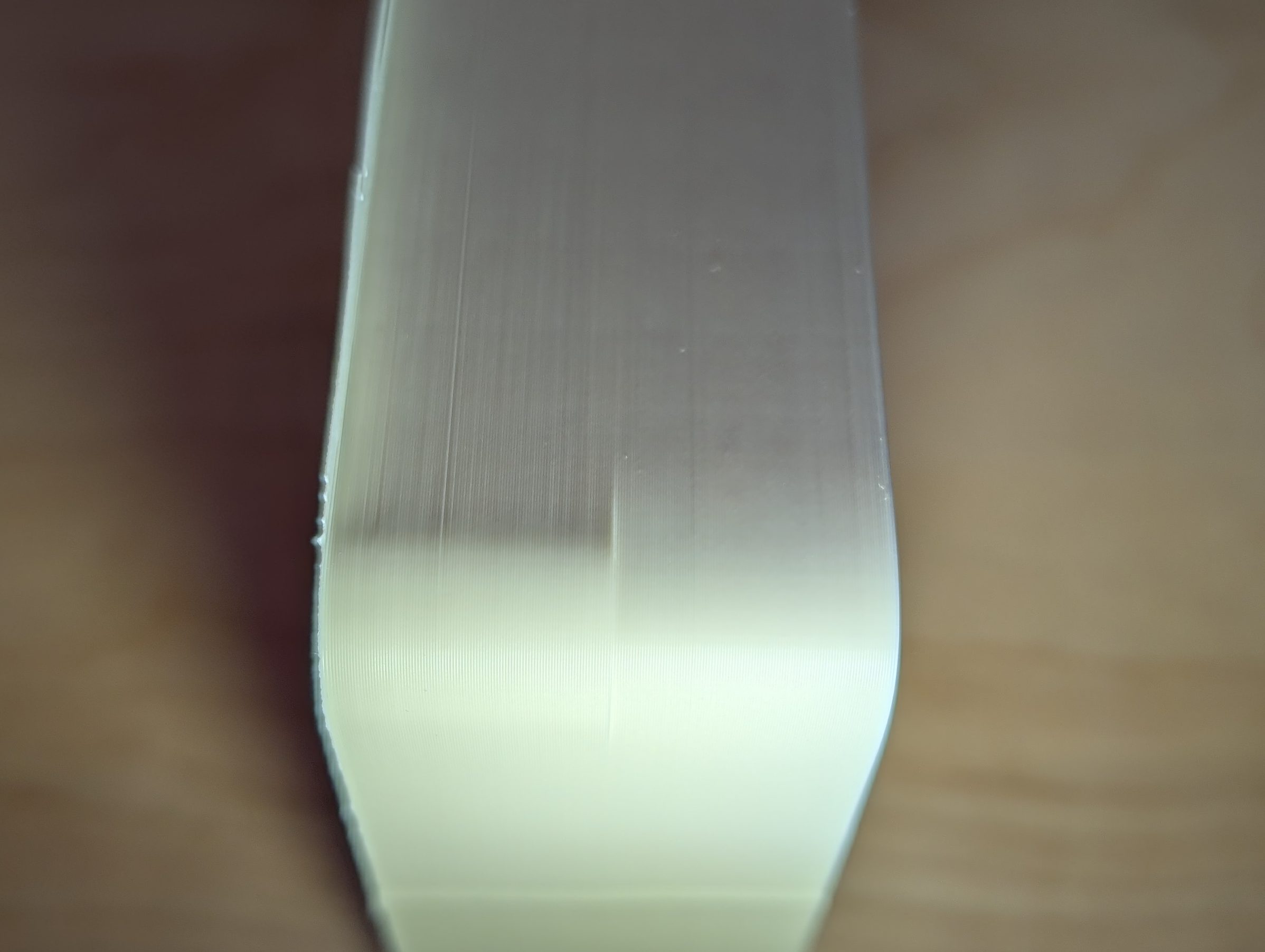
The curve on the left is a radius, and on the right is a G3 curve. You can see the very tiny shadow on the radiused side, while the G3 curve is smooth. I think this is both a print artifact from deceleration and a result of my careful lighting, but based on the geometry I also expect a little discontinuity there. I can also feel a slight “hitch” in the smoothness as I slide my finger around the curve.

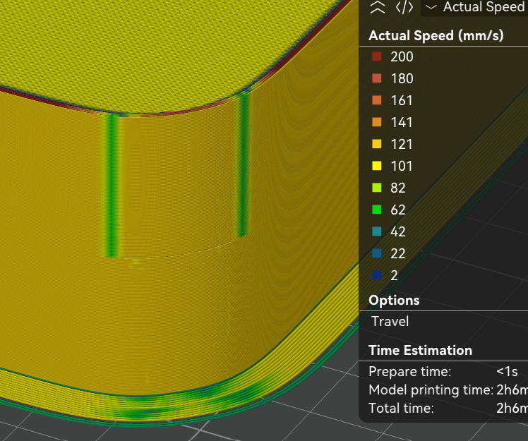
This is a different corner, where the radius is on top and the G3 curve is on the bottom. You can see where the deceleration happens in green, as the print head cannot move smoothly around the corner at high speed.

Unsurprisingly, these smooth curves have tons of more important uses in the real world, particularly in transportation, where smooth curve transitions are used to prevent trains from derailing, cars from flying off of roads, and (least importantly) they are famous for being the non-radius shape for corners that apple uses. They are also used by industrial designers to terrorize mechanical engineers everywhere. There is nothing quite like getting a model with no flat surfaces and no radii that explodes when you sneeze at it, and these curves seem to be amazing for building that kind of geometry.

In my own life, I might start using them to replace radii in my 3d prints, at least when they are in the xy plane of the printer, so they come out extra nice, and ever so slightly faster. I also intend to use them on future woodworking projects to avoid the odd looking corner that I shared above, which is the real reason I made this plugin.

StenciLaser – How to cut solder paste stencils on the Xtool

After my initial success with cutting metal stencils on the xtool F1 ultra, I realized that the re-ordering and careful setup of the stencil by hand would really put a damper on my stencil making enthusiasm. Having to re-order hundreds of vector paths by hand is time consuming, and its not easy to visualize and certainly difficult to optimize. Fortunately, this is a fairly straightforward problem of ingesting a file, doing some algorithmic stuff to it, and looking at the output. The perfect kind of problem to take on with my new pal, Claude.

What StenciLaser does:

StenciLaser is a program that takes a DXF and creates an .xs or .xcs file for the F1 ultra where the cuts are ordered to minimize heat affected zones and warping. These thermal effects happen when the laser focuses a lot in one area. For thick substrates, its not as much of an issue since stress will just build up in the part, and be relieved later when it cools. However, with thin parts, the heat is enough to cause permeant deformation of the the part.

To avoid cutting a lot in one place, we need each cut individual cut not to warp the material, and then cuts also need to be spread out as much as possible. I can’t claim that the approach I took will never warp a stencil, but its pretty good. StenciLaser takes all the apertures and breaks them into groups of equal quantity, then goes round robin around the groups and chooses one aperture to cut. The chosen aperture is the furthest from the last cut, and is weighted to also avoid the last cut inside the group. The round robin chooses the furthest group from the last cut.

Finally, the program packages it all up into an .xc or .xcs file. One thing that seems to work, but that is not officially supported is infinite layers. This is important because the only way to get the xtool studio to respect the cut order is to go to processing->cut order->by layer. With only 16 layers (the default) xtool studio will not fully respect the optimized cut ordering, which is a big problem.

Issues+Future work

One issue with this program, possibly due to the infinite number of layers, is that processing in xtool studio takes a long time, especially with many repeats. I found it easier to set repeats to 10-50 and just press the button multiple times rather than wait forever for the processing to be done. This step can take several minutes, but since it happens in the xtool code I can only guess why it takes so long. Possibly it struggles with so many layers, or maybe the number or unique cuts and “travel moves”.

The algorithm is also not perfect. There are some trivial degenerate cases where it might produce bad output, like a very dense grid of rectangles, or having very few cuts to do that are close together. One issue is that the algo is “greedy” and might run out of good candidates while maximizing distance in round robin, instead of maximizing average distance. So far the greedy distance algo seems to be ok in most cases, but it could be an improvement to change to maximizing average distance.

The other issue is that there is no way for the program to “pause” right now. So if there are two rectangles right next to each other, they will just get cut one after another, even though it will cause a lot of local heat. There could be a solution to this too- even though there is no “pause” to put in, a large path at a low speed/intensity could be drawn to waste time. However, this hasn’t been an issue since usually a stencil has a lot of cuts in it.

There are cool improvements to be made too! For example, laser cutting stencils can leave burrs for a couple reasons- either from melt-freeze or from “tabs” that get broken either from heating/cooling and expansion/contraction, or from later manual removal. It would be interesting to add a deburring or even an aperture (vertical) keystoning pass similar to the “aperture enhancement” that is sometimes offered on commercial stencils.

How to get and use StencilLaser

Go here: https://github.com/Aylo6061/StenciLaser. There are instructions for use there. Be sure to set cut order->by layer in the processing menu of xtool studio! or it won’t work.

What I think about Claude Code

This is the kind of problem that in the past, would have required a lot of work on my part that I have historically not been great at, or very interested in – setting up a GUI, making sure the data stays synced with the gui, making sure buttons are the styled right, making sure dividers and cells resize nicely etc. In this case I was able to get a tested prototype done in an afternoon, which is incredible. It even has an ok installer, which should make it easy for me to share this, and which is something I would have avoided making in the past.

There are many complaints about various AI programming tools, but I’ve been overwhelmingly impressed. I think this technology will really let people write super niche software, to solve really specific problems for specific users way faster than anything else ever has. More importantly, I’ve taught a few non-technical people to vibe code, and they have been able to develop software for their own problems. It will be exciting (and scary for some people, like IT admins) to see what people do with this new tool.

PCB Stencils (or tiny metal parts) on the Xtool

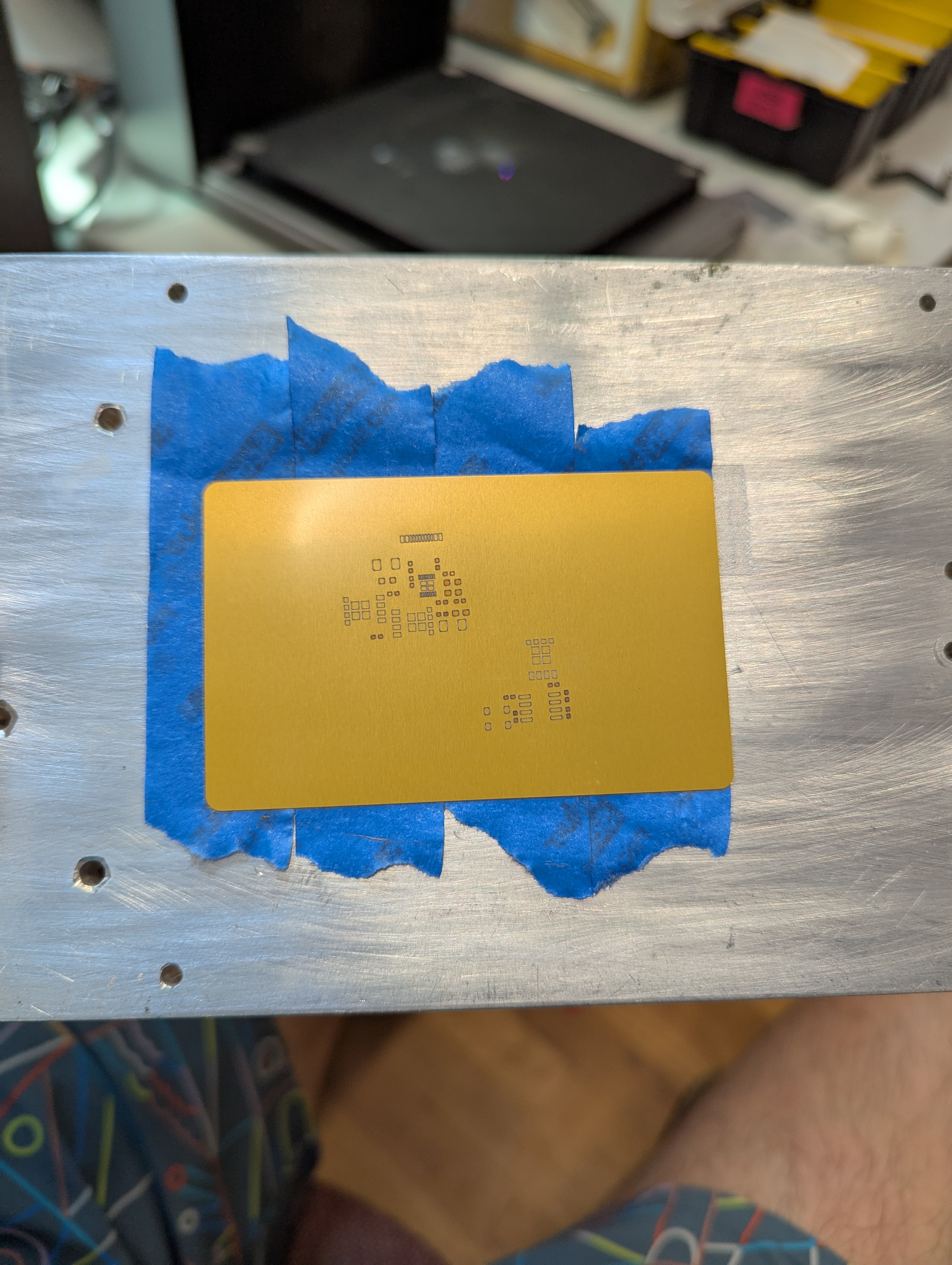
Lately I have gotten access to an xtool F1 Ultra. One of the advantages of this laser is its ability to ablate (I wont say cut) metal. I’ve seen videos of people making pcb solder paster stencils, or cutting really thin metal on similar fiber lasers, and I wanted to try too. All of this is applicable to making small “positive” parts with the xtool as well. Here are my notes.

Settings and Cut Ordering

Note extremely thin webs between holes!

When working with thin material, its important not to heat the metal up too much in one spot. This means making many light passes is better than a single, really aggressive pass. This is especially true for cutting out tiny windows, or cutting out a thin “web” between two windows. Too much heat too fast will distort the final geometry.

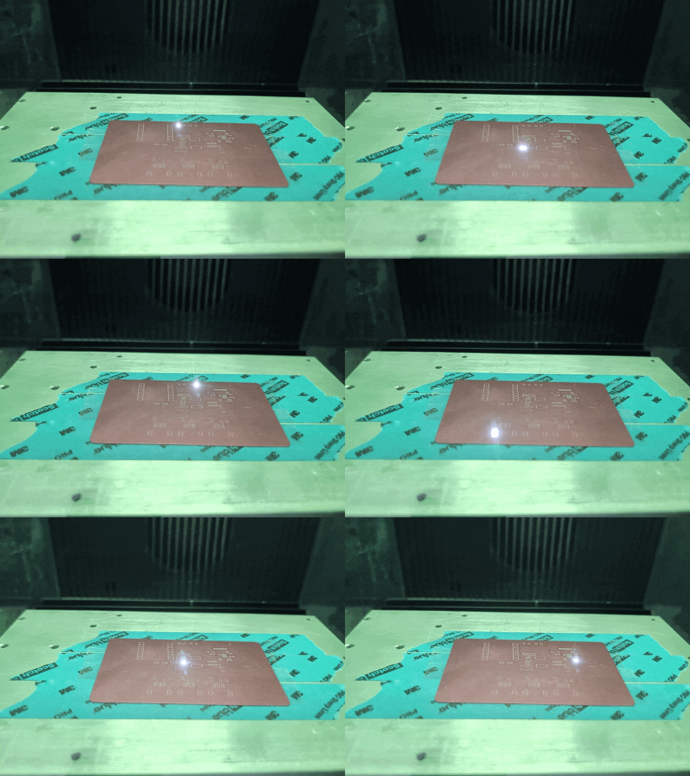
The settings I used were 100% power, 8000 mm/s speed, and a variable number of passes. For a single large cut/window (like a ~3mm square or above) you can just go ahead and set it to 500 passes and let it rip. The cut is long enough that by the time the laser comes around again, the heat has had time to conduct away.

Below about that size of window, I had better results from repeated cuts – e.g. cut 50x times, wait 10 seconds, then repeat 10x for a total of 500 cuts.

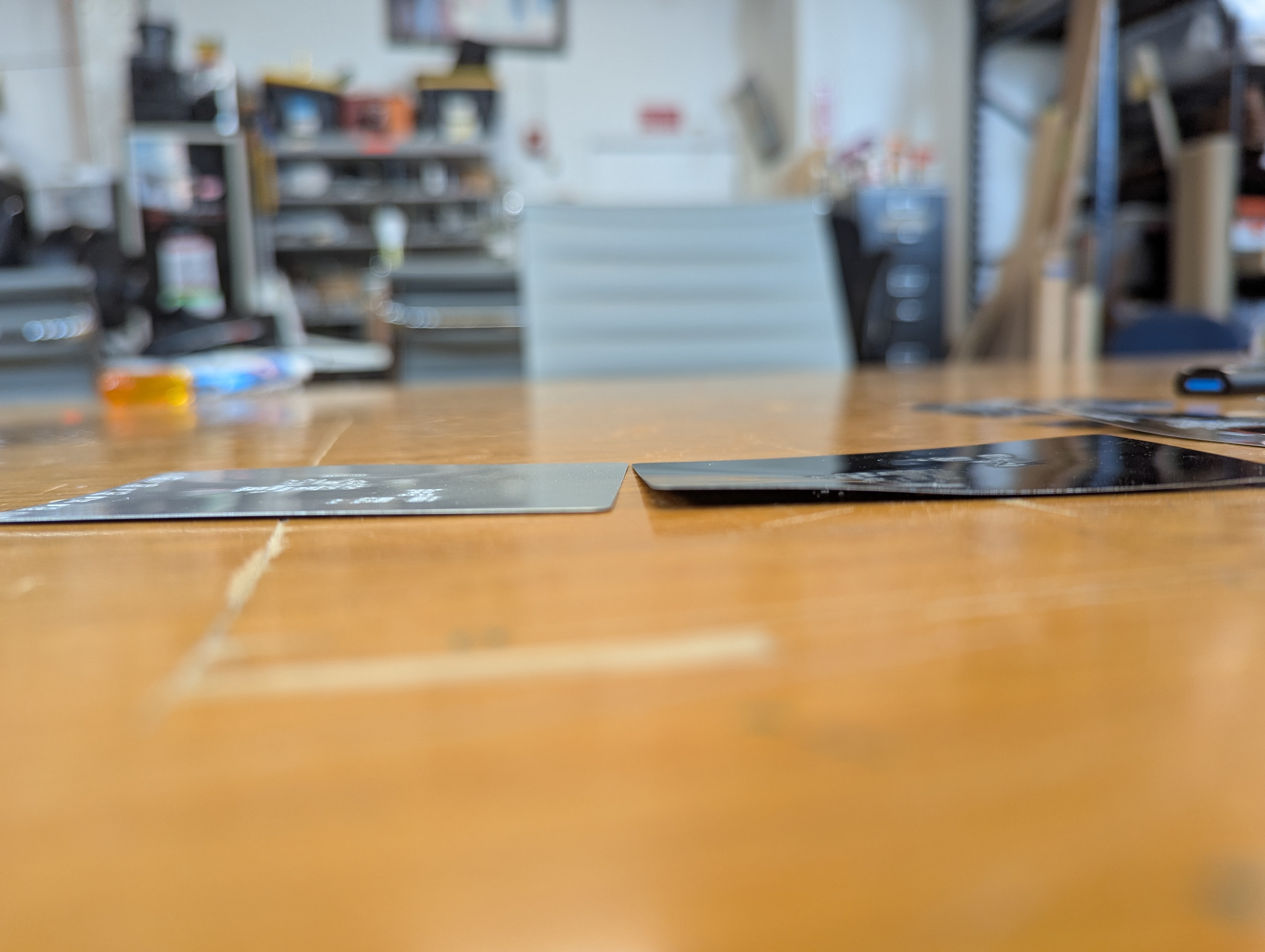
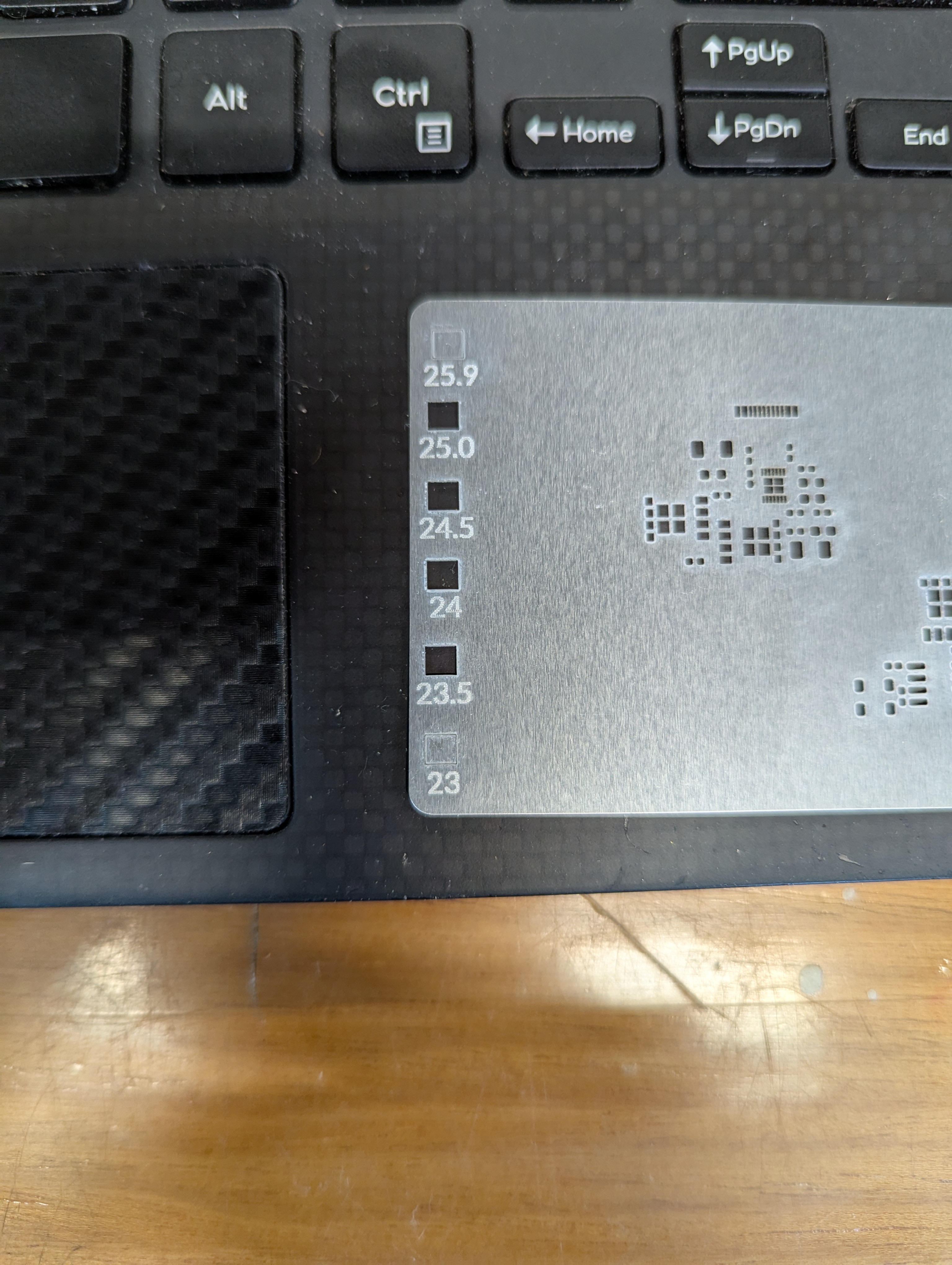
In addition to taking many passes, I needed to semi-randomize the ordering of the cuts. The Xtool sofware optimizes for time, by cutting from the top left to bottom right. This means that cut profiles that are next to each other together are done at the same time. This leads to overheating local overheating, and warping. The left stencil was randomized, the right one was not.

Sadly, there is not feature to do this in the xtool studio. The best you can do is select->ungroup your stencil, then go through and assign each cut in your stencil to a different layer. Then, using the “…” menu near the process button, choose processing path-> user defining and choose “by layer”. There are about 10 default layers, so the laser will go “somwhere else” for about 9 cuts before returning to where it was cutting before. This greatly reduces local heating.

Workholding to Prevent Warping

Warping happens when some part of the aluminum gets so hot that it expands, and causes plastic (permeant) deformation in the rest of the sheet of aluminum. To avoid this, I constrained the sheet with tape. This prevents deformation in exchange for stress in the aluminum. By minimizing heating, we minimize this stress.

This fixturing also holds the aluminum material so it doesn’t move due to the exhaust fan.

The best way to achieve this fixturing seems to be an aluminum block (safe to laser), then a layer of removable double sided tape, then another layer of painters tape, then the aluminum stock. Without the layer of painters tape, the aluminum card is hard to remove without bending. The painters tape releases from the doublestick pretty cleanly, so a single doublestick tape bed can last many laserings.

Focus Focus Focus

One issue I have run into repeatedly with this laser is that the autofocus does not work, at all. I guess its better than nothing, but I find that its off by about -3mm-4mm. So every time I create a new fixture, turn the machine on, or jog anything, it needs refocusing. I just start by taking the autofocus distance, subtracting 3, then I focus by .5mm increments until I go through a “sweet spot”. It seems like for metal ablation, the beam is tight enough to be focused over about 1.5mm

Surprisingly, the laser cutting makes a distinct snapping/humming sound when its cutting well. I assume this has to do with the metal rapidly expanding/contracting as the laser heats it up and deforms it.

Stencil Performance

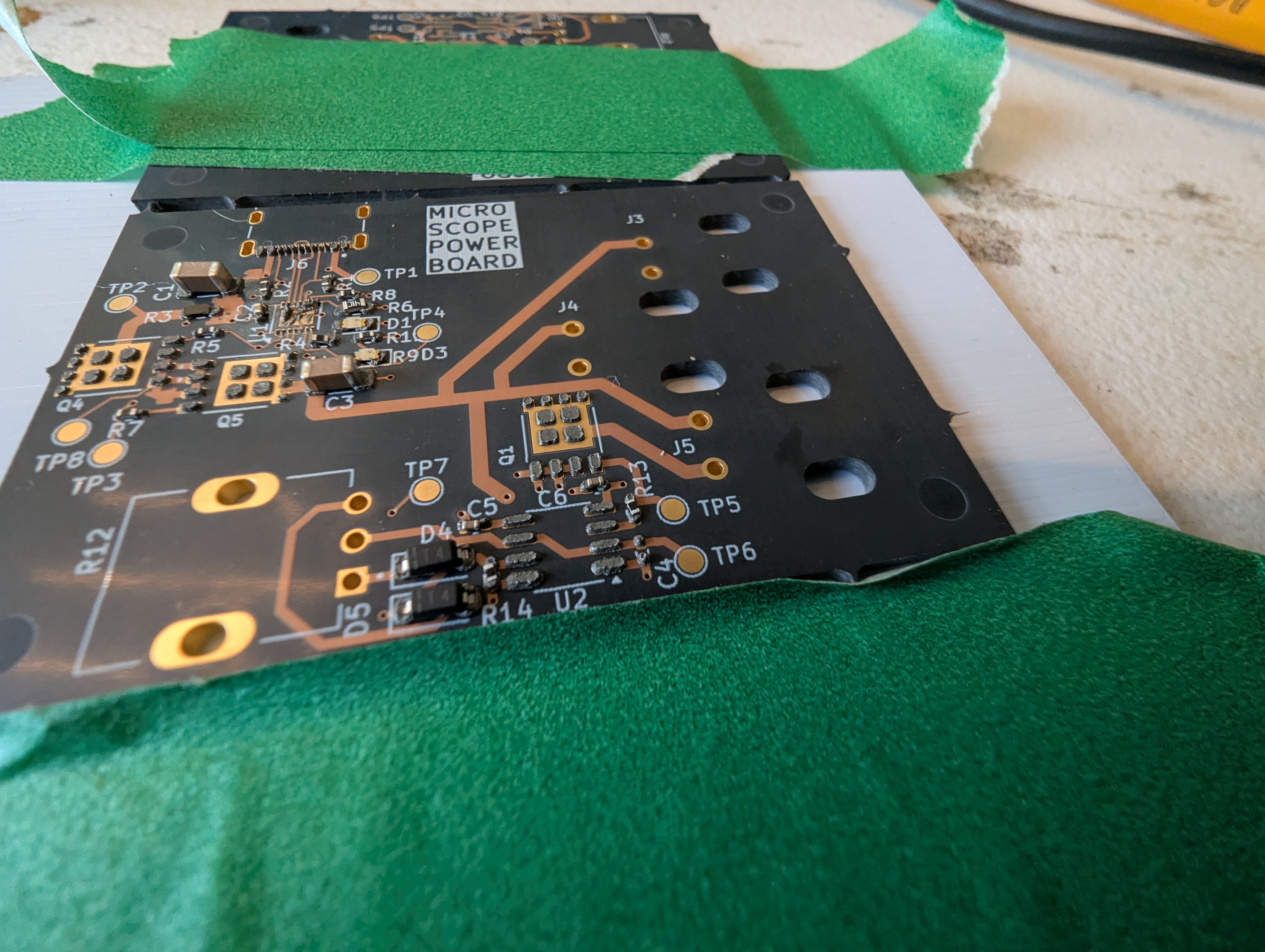
My hope is that this can make stencils for everyday use, and for emergency use, like pcb rework. PCB stencils usually cost a couple bucks and cause a few cost related problems for ordering PCBS – specifically in the US, the stencils are relatively expensive (if coming from somewhere like sunstone), or you have to get them at a separate website with separate shipping (osh park/osh stencils), or if you are ordering small boards from overseas, stencils make shipping really expensive as dimensional weight goes up (the box is bigger).

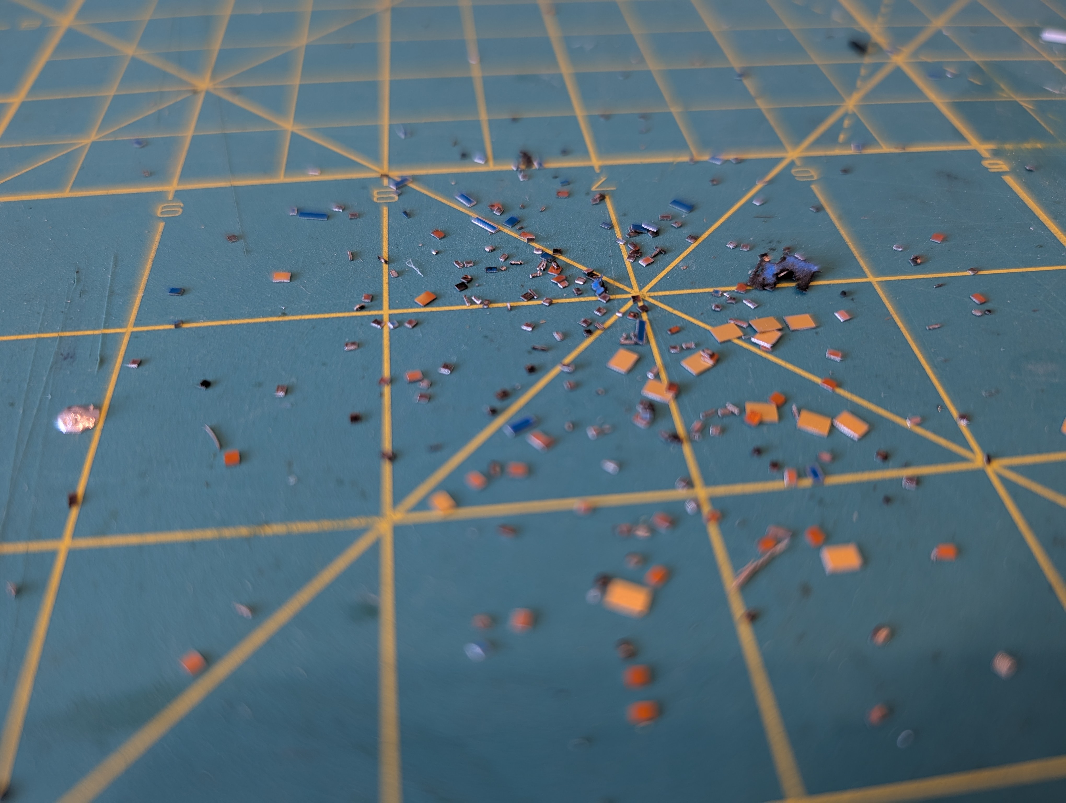
This stencil was quite usable, but it seemed thick (around .18). In the future, I’ll try a slightly thinner material to reduce paste application, especially for “middle”/large pads. The good thing is that its easy to delete or reshape the windows for components if they cause trouble!

Lingonberry – First Leaf!

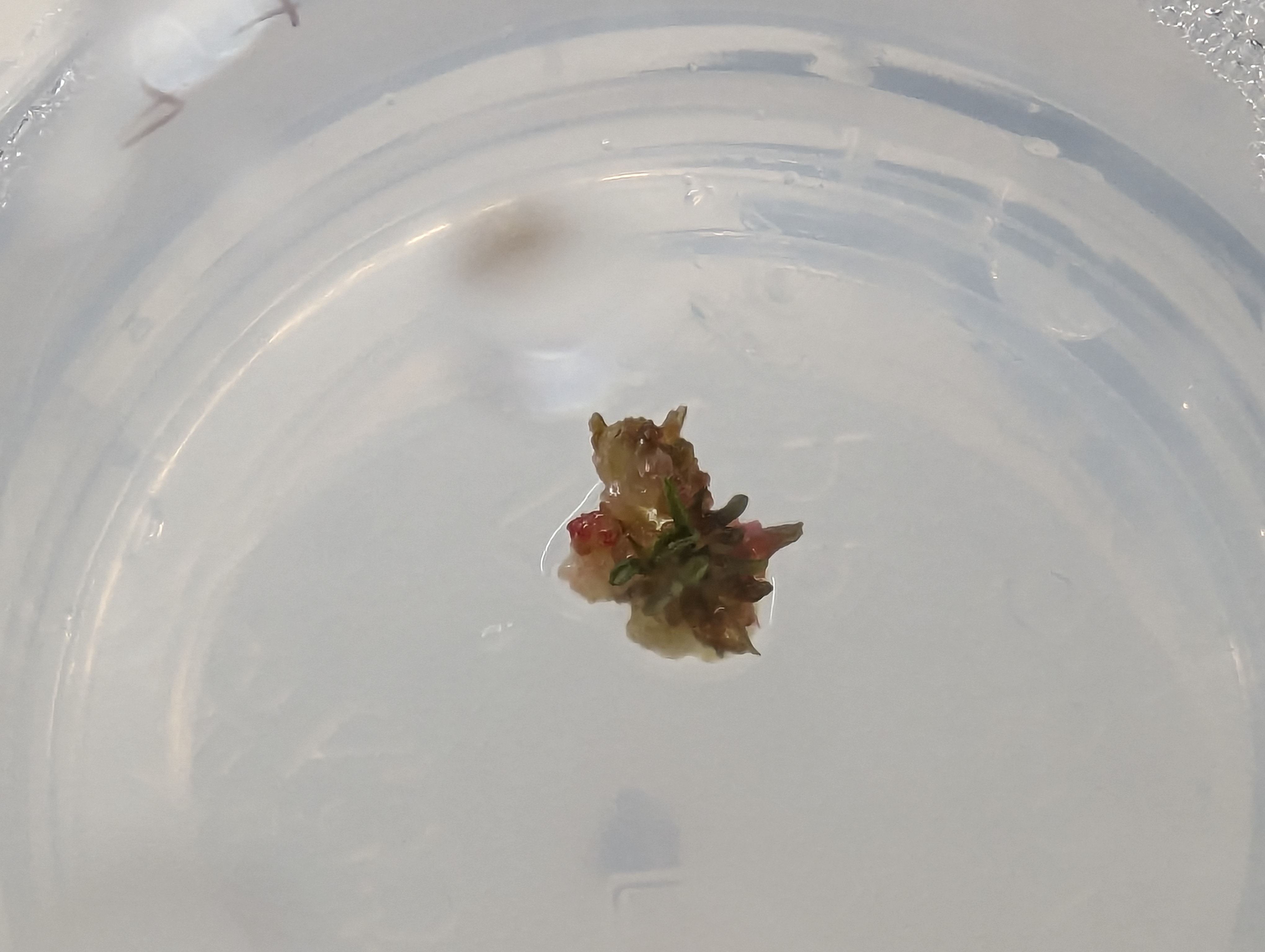
UnbeLEAFable! This is a tiny leaf growing from a callus culture, produced from a tiny cutting harvested from the wild. This is exactly what I expected (and hoped) would happen with this project. In a few more months, I hope to have rooted plantlets that I can transfer to normal soil media for hardening! Once the plants are rooted in soil, I will write up a detailed procedure on the whole process.

Wide Temperature Range Thermistor Use

Reading a thermistor seems like a pretty straightforward task, and there are a lot of guides on how to do it, either using just the beta value, or using the full set of coefficients for the Steinhart-Hart equation. I wanted and needed to do something a little different, because I wanted to measure temperatures somewhat accurately over a wide range (25-200C) with a single thermistor, for an upgraded version of the PCB hotplate.

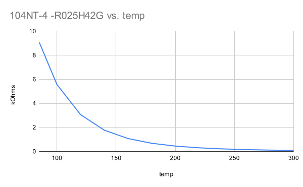
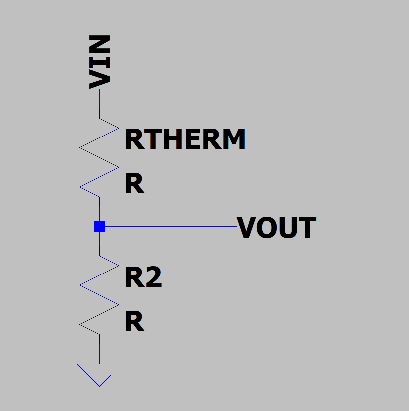
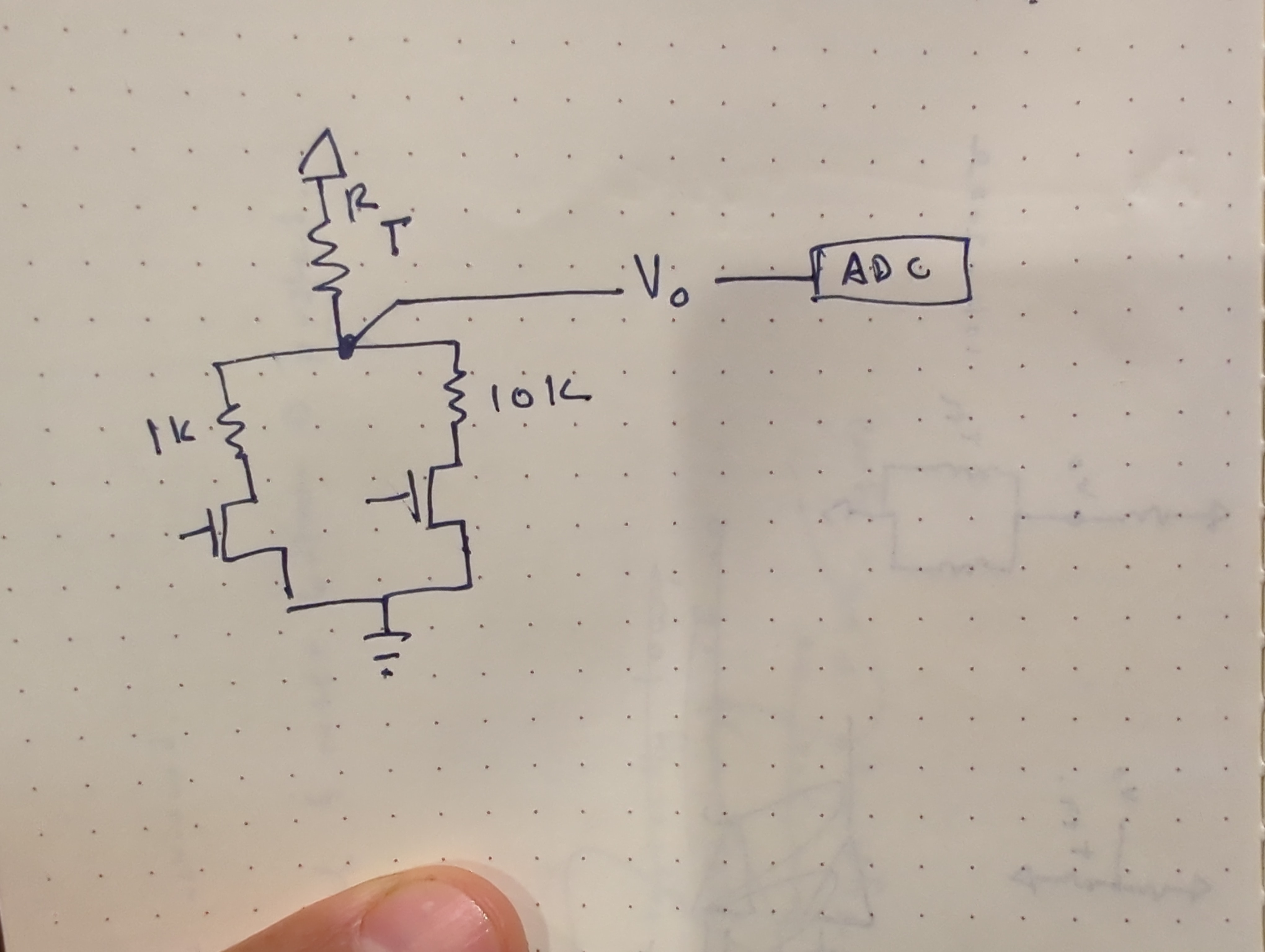
Measuring this range is difficult because the resistance of the thermistor changes a lot over the range I care about. at 25C, this particular model is 100k ohms, and at 200C it is about 1k ohms. It is very not linear, changing very rapidly at first. Thermistors are often used in a voltage divider, where the output voltage is related to the temperature of the thermistor:

This causes a problems for my implementation because choosing other resistor in the divider causes the most sensitivity near the value where Rt=R2. That is, the temperature sensing will be easiest near where the thermistor and the other divider resistor have the same value.

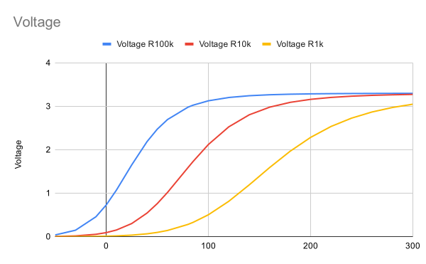
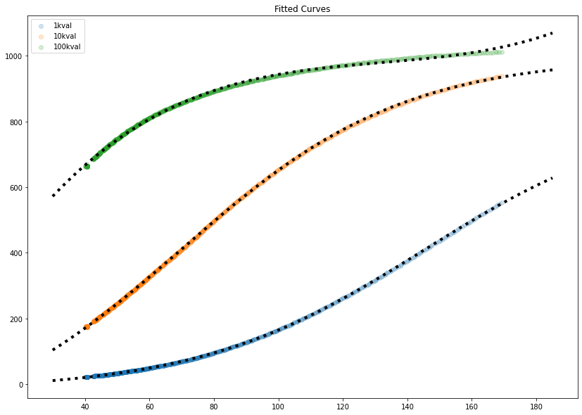
This is a chart showing the expected output of a voltage divider with three different resistor values, computed from the temperature-resistance chart plotted above. The steeper the curve, the better, since a small change in temperature will create an easily measurable output. But none of these curves are linear across the whole range that I care about, from 25-200C. Instead, the 100k looks good from 0-50C the 10k looks good from 50-120 and the 1k looks good from 120-200. At the center of each of these ranges is where Rt=R2, and the output of the voltage divider is about half the input voltage.

My solution was to use several different resistor dividers instead of a single resistor divider. The final implementation uses an analog mux instead of discrete FETS, and included a 100k resistor divider as well.

Calibration

While it would be possible, through first principles and careful measurement, to figure out some mega-equation for all these components, I decided it would be a lot easier to write a script to calibrate each “channel” of the measurement. These thermistors are calibrated against a thermocouple, which was the original sensing element on the hotplate. To collect calibration data, I just measured the hotplate with the thermistor and thermocouple taped together. This produced the curves above, as expected from the simple simulation. Shown in black dots are fitted curves- the bottom two fit a sigmoid/logistic curve, and the top one (which didn’t have enough data to fit to a logistic curve easily) is fit to a 4th order polynomial. The 100k resistor values (green, top line) were pretty useless above 40C, quickly flattening out.

These curves give us a value that predicts ADC ticks for an input of temperature. The inverse is really what we are after, but that is easy to do mathematically.

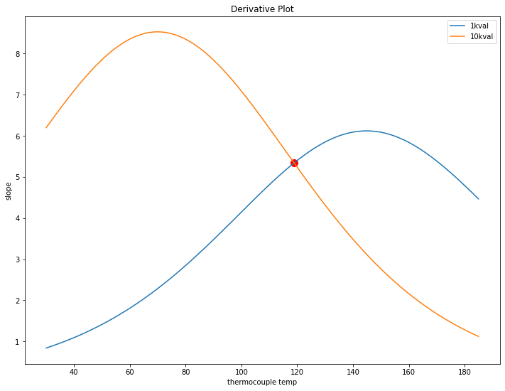
Looking at the two remaining 10k and 1k curves, the question is where to swap from one to the other. The goal is to keep the amount of ADC counts per degree C as high as possible over the whole range. This can be found by inspecting the derivatives of the fitted curves and finding where they meet (in this case, just around 120C).

This chart also shows why exactly a single value for R2 in the resistor divider would be bad. For example, below 40C, the 1k resistor shows less than 1 tick per degree C, so a 1 degree change would be hard to measure there.

Limitations

This was done with a single set of data, so it may not be accurate for all time. Taking more data in the future would be neat, especially because the python script for analyzing the data will just spit out numbers. It would be interesting to compare the calibration coefficients for various data sets to figure out how much they change, run to run. Hopefully it would be a small amount.

Solution Cost

The reason I didn’t go with a thermocouple is that the reader and the thermocouple alone would cost about $10 in parts. I usually buy multiple ICs per prototype (in case of an accident) which would cost something like $15-20 in parts. The parts for the equivalent thermistor solution cost about $2.50 per unit, which is cheaper than just the thermocouple reader IC.

Lingonberry Cell Culture – Rooting

I have reached the point where I have enough lingonberry cell mass to try rooting a few of them. This is done on different media, and since I want to have these develop into plants with leaves and roots, I can’t do it in a petri dish!

Instead of using a purpose-made plant growing container, or even a polypropylene takeout container, I am using some condiment containers I have left over from the original cell culture experiments I did a few years ago. These are half polypropylene, which is autoclavable, and half polystyrene, which is not. To use these, I autoclave the bottom half and soak the other half in bleach while the autoclave is running- when the parts come out, I pour media and fish a lid out of the bleach. it seems to work well enough against contamination.

The media is woody plant media with MS vitamins and zeatin, per the recipe in Plants from Test Tubes. I poured a few CM into each cup (these are large condiment cups, not the tiny ones).

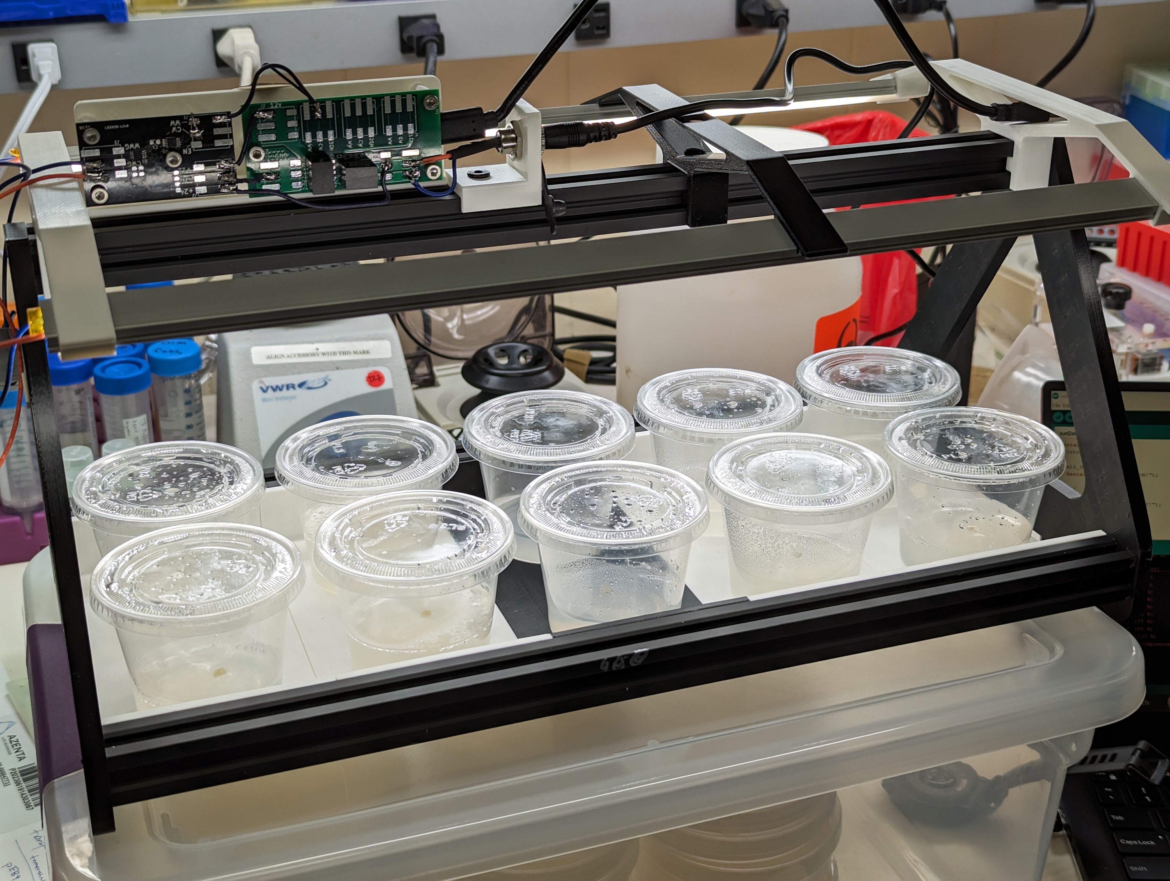
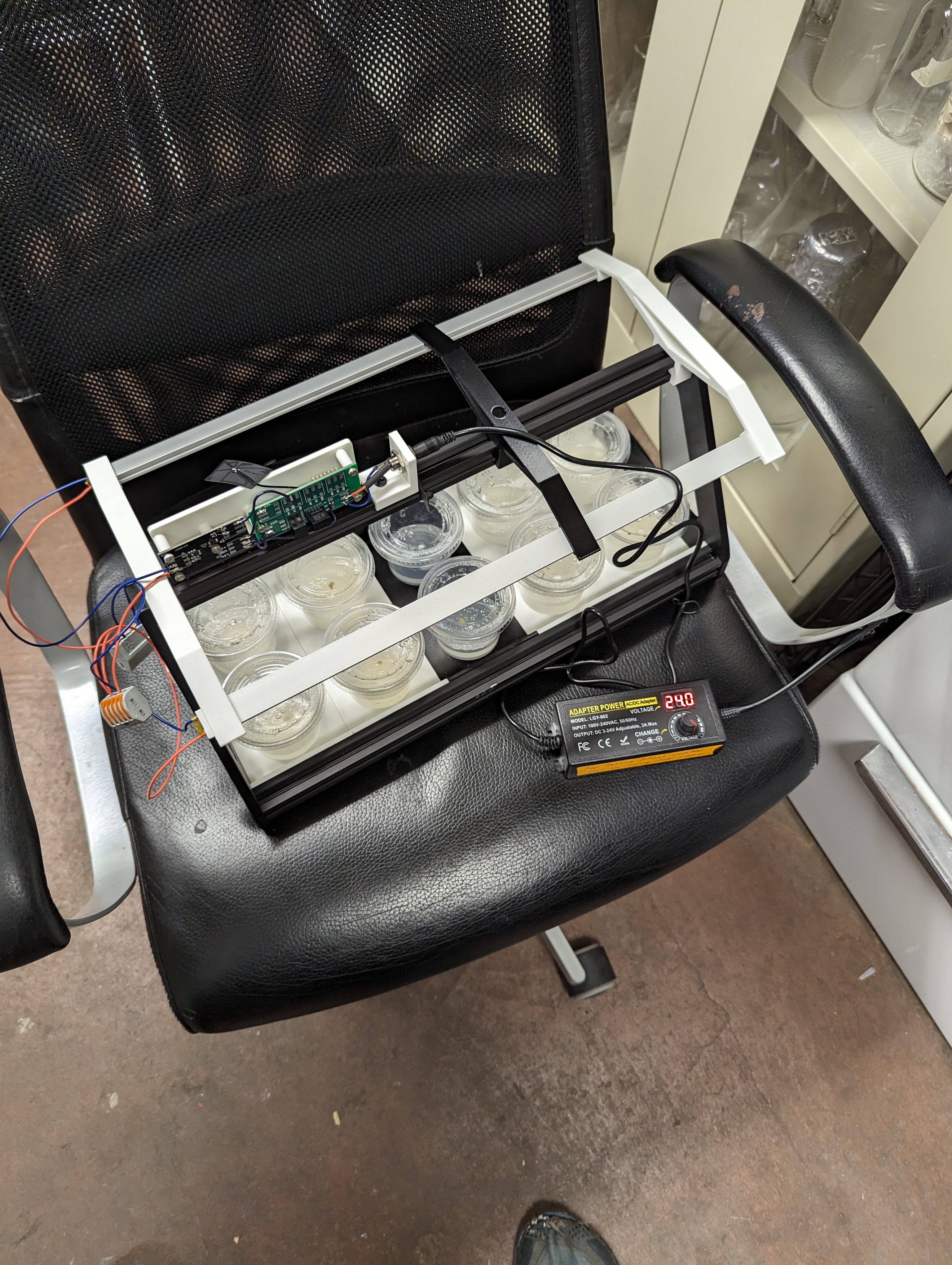
The basement chair of rooting

During rooting, it seems important to have a source of light so that the plants can start making their own sugars. These are growing in a basement, which is roughly “room temperature”, but there is not much light down there. I built a rooting tray with overhead lighting for the plants. It is mostly built off of the hardware for the “SunDown” lamp that I built. The hardware is a little overkill, but modular enough to be recycled into future lighting projects.

Lingonberry Callus Cell Culture

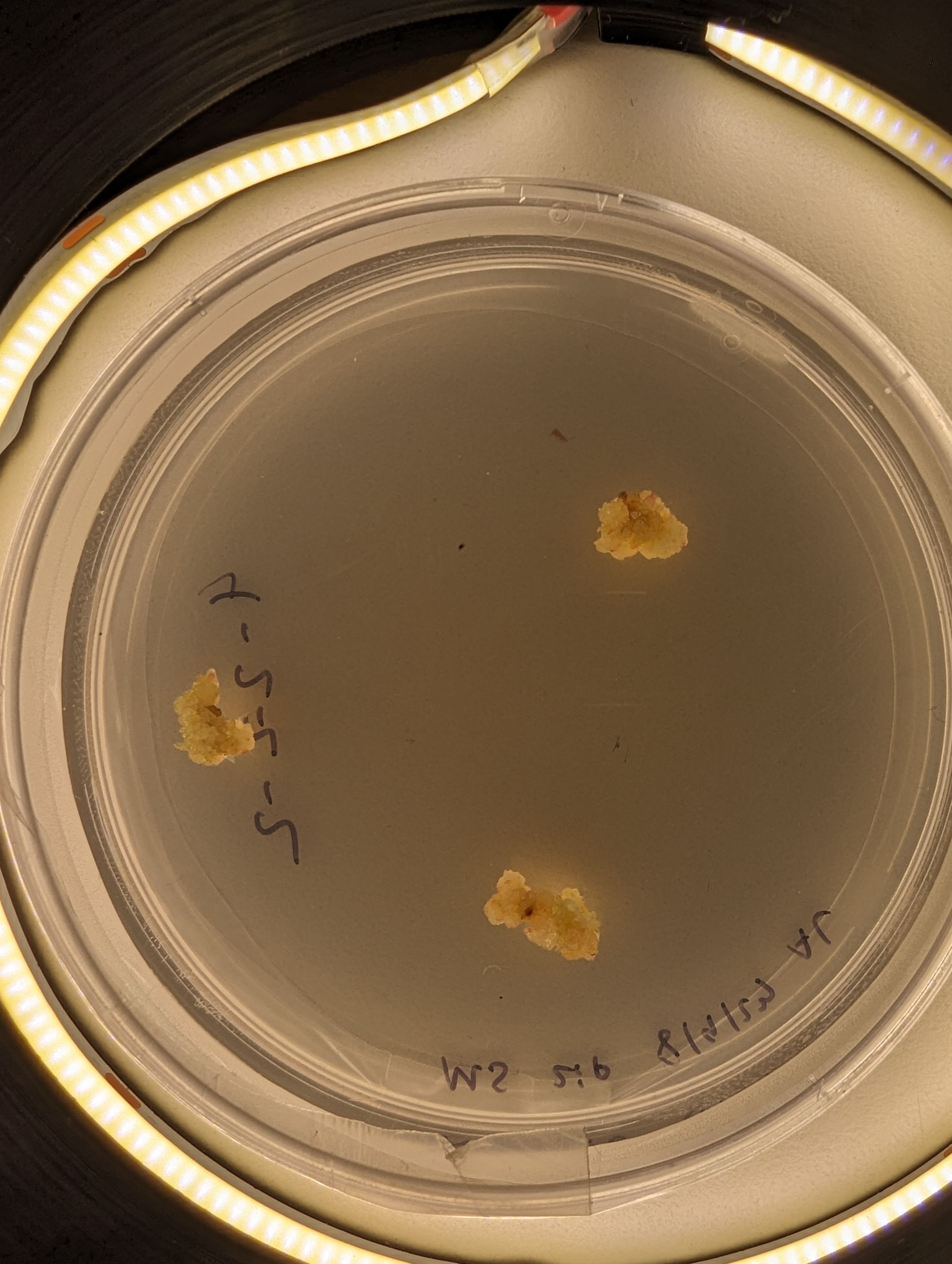
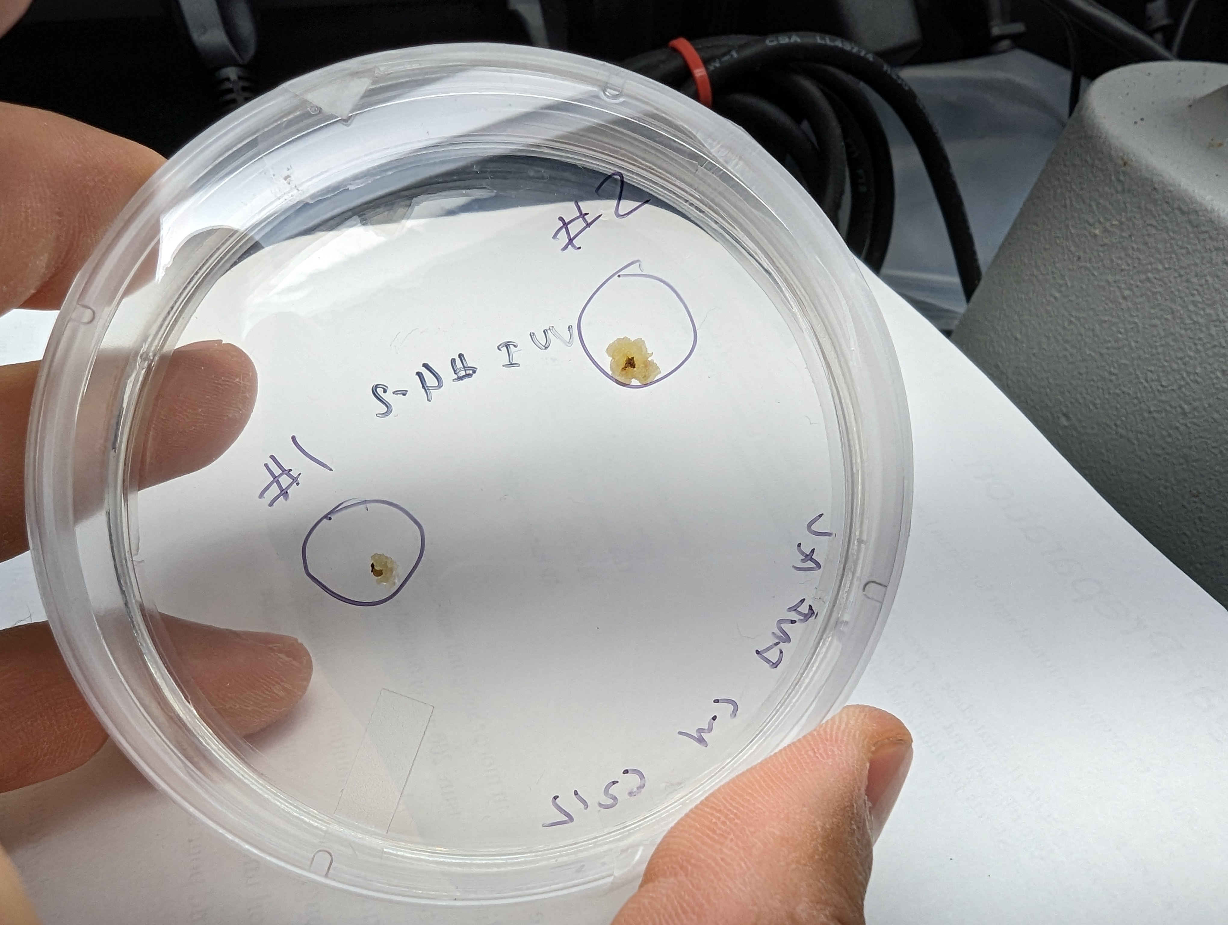
I’m back at trying to propagate a lingonberry plant from a cell culture gathered from the wild! This time, I seem to be having a lot more success in terms of growing something that at least resembles a callus culture. Encouragingly, I have had similar growths from various parts of plants that I plated. I tried to excise buds from the meristem, without magnification, so its hard to say exactly what tissue the cells came from, because they were very small (generally, they are from in the buds).

In the future it might be worth looking at callus induction from leaves, a technique I did not know about.

These cultures are growing relatively slowly (months between re-plating), possibly due to the totally uncontrolled and unoptimized conditions they are in, aka an funky basement. Surprisingly, contamination has not been a huge issue (transfers have been done in a pcr hood).

The next step will be to take some larger cell masses and try to get them to grow a bud, shoot, root or leaf- to start turning back into a plant. My plan is to grow them on a deeper media in a different container, undera lighting, without 2ip on something like WPM with zeatin (although zeatin is expensive, so maybe just WPM!).

Further Foraging Finds

While rainfall has been blocking climbing, it has been causing a lot of mushroom fruiting in the white mountains. This latest trip was theoretically to go climbing at cathedral ledge (which did happen), but it came with a heaping side of foraging.

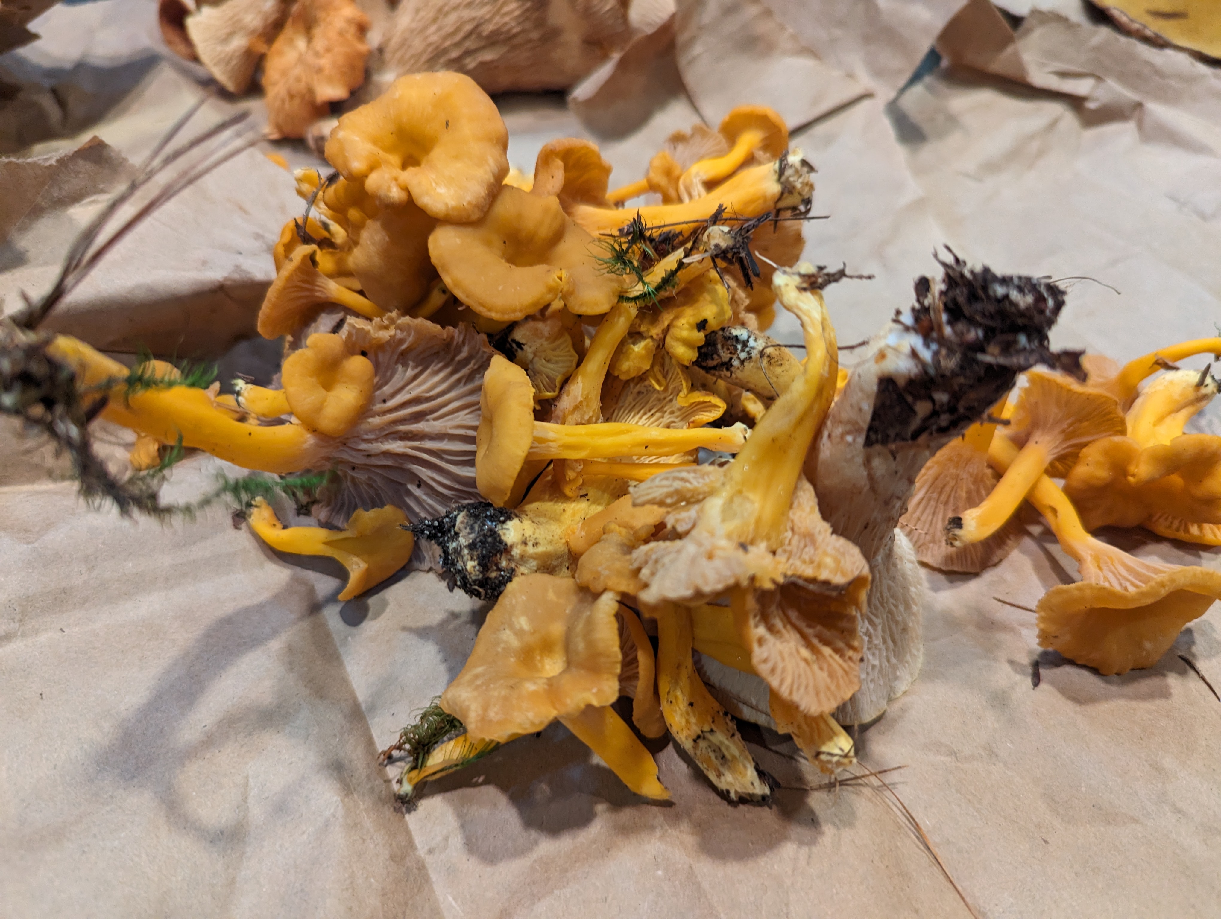
Among the fungi I found were: red cracked boletes, trumpet chanterelles, and regular chanterelles. I also found a number of boletes that I found difficult to ID, and a vase-shaped fungus that people call a scaly vase- these are rumored to be inedible, so I did not eat them.

People seem to be on the fence about the red cracked bolete- in my opinion they are certainly food.

Novelty-sized Bolete

This thing was huge-easily 7″ across, with the dark bluish staining on the cap where it was cut and green staining on the yellow tubes/pores on the bottom. the cap was cream colored with brown. It looked tasty but without a positive ID, I decided not to eat it.

Mystery Bolete

At first I assumed this was a cep due to the “netting” pattern, but the flesh seemed to bruise. I have not figured out what it was, but maybe once I am more familiar I will figure it out!

Eating the Rumney Parking Lot

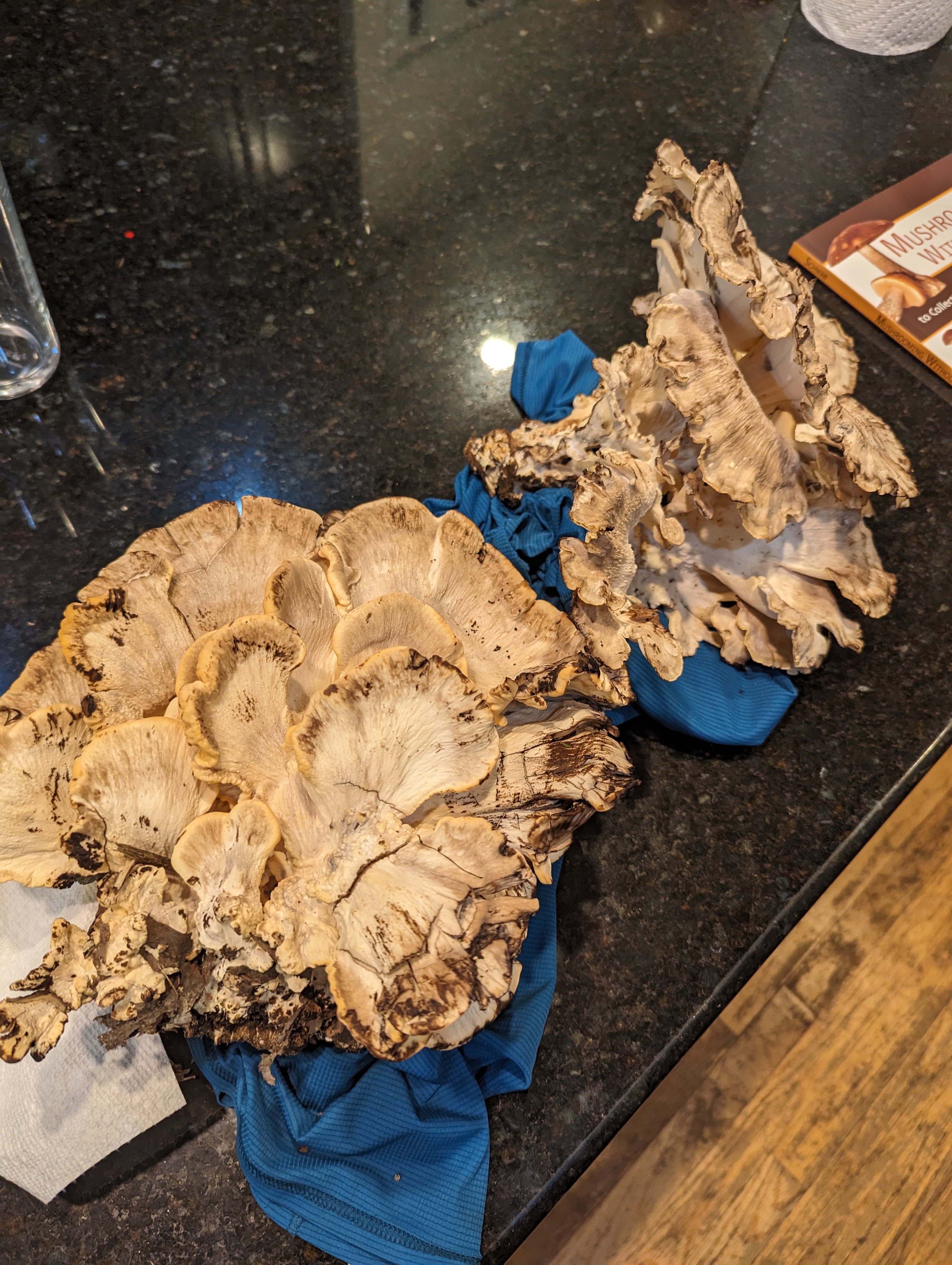
With all the rain that has been happening this summer, mushroom foraging seems to be going quite well. I have already casually encountered Chanterelles, and horn of plenty in pretty high traffic areas- but this was my first time finding a giant polypore – the creatively named black-staining polypore.

A few steps from the edge of the rumney parking lot I found a few large clumps of grey and white mushrooms. I know that most large polypores are ok to eat, and after misidentifying them as hen-of-the-woods I realized I had a different mushroom on my hands.

The giveaway was the “black staining” nature of the mushroom- breaking off a little piece, or bruising the mushroom causes it to blacken. The fronds (?) are also a lot wider and meatier than hen of the woods, closer to 4-5″ across and not very symmetrical. These are edible, and I second the general opinion of many posts online suggesting that it is preferable to eat them when young. These became a very mushroomy broth, and a few choice fronds were baked/stewed (confirming chewiness).

High Speed Nature Walk: Franconia Ridge

I was curious to see what the lingonberry plants looked like up on Franconia ridge. To this end, I took a high speed nature walk up the falling waters trail to middle haystack, over to Lafayette, and then back down to the parking lot.

This trail is an interesting slice of biomes in the notch, and it is (rightfully) one of the most popular trails, coming in at about 8+ miles and around 4k of gain, with good parking, it’s also very accessible.

The falling water trail zig zags up to middle haystack, crossing a stream/waterfall several times. This area is always wet, and due to the recent high rainfall, some of the crossings were a little harder to navigate.

Once gaining the ridge proper, the forest drops away and you are in the alpine of the northeast! The soil is sparse and rocky, well drained and likely acidic. This supports two plants that I am interested in: Lingonberries and Blueberries.

Nature Notes from the ridge

beefy blueberry bush

In contrast to the alpine garden trail/general mount Washington environ, the lingonberries/blueberries here seem to be a lot smaller. I suspect that is because there is a lot less soil due to the ridge being pretty exposed to the elements. Most lingonberry bushes were much smaller, with the plants being more individual instead of large mats. The blueberry bushes were low to the ground, but still large. Both the lingonberry and blueberry bushes are just starting to flower, although there were a few unripe adventitious blueberries hiding in the brush.

small lingonberry bush

Interestingly, the blueberries seem to dominate here. The bushes are large and healthy looking, and there seem to be many more blueberries than lingonberries. I wonder why that is. I stayed on the trail since its a high traffic area- maybe blueberries have some advantage in taking over disturbed territory? who knows.

Nature Notes from the Bridle Path

Due to the absolutely torrential rainfall that the northeast has been experiencing, the forest is DAMP!

That means there are a ton of mushrooms fruiting. I don’t really know anything about these, but it was interesting to see. Some of these are from a small forest down the road from the ridge.

Trail/Nutrition Notes:

This hike took about 2 packets of gu and 2 packs of gummies, and just under 3L of water. It was hot hot hot! Falling water trail is fairly steep and rocky/slippery, but once on the ridge its smooth sailing to lafayette. There is a steep/wet/rocky section on the way down from greenleaf hut, but once that is passed it is easy to jog back to the car.