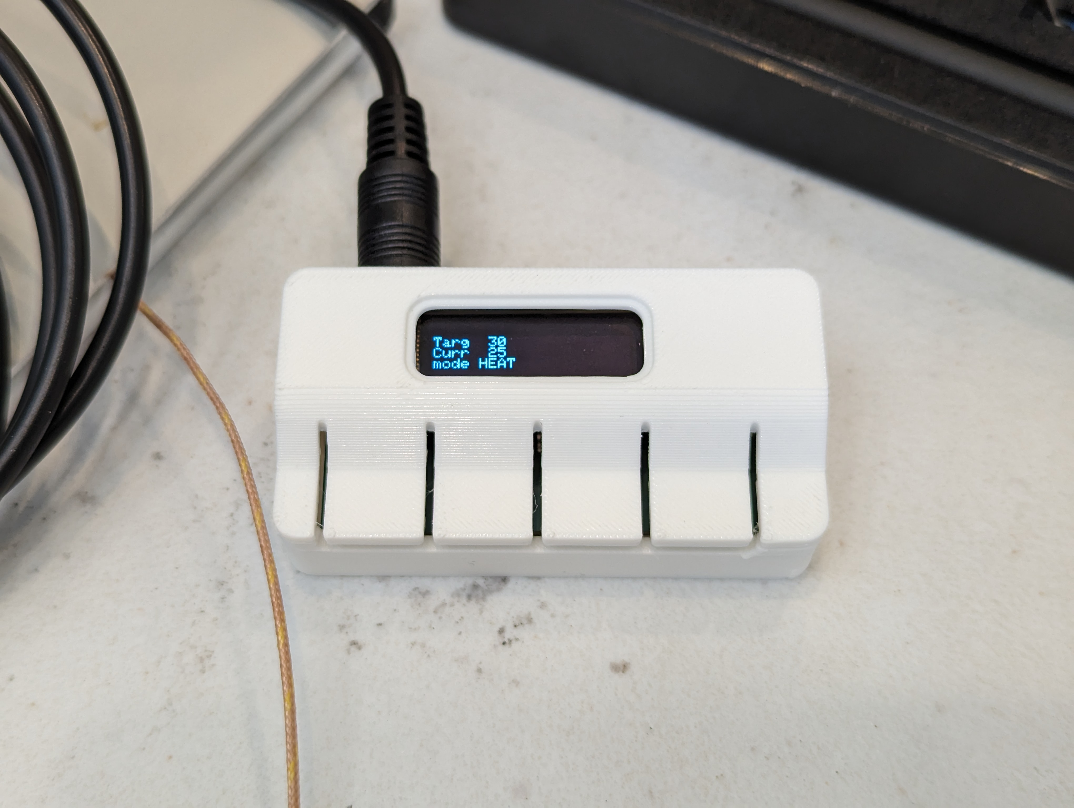
Reading a thermistor seems like a pretty straightforward task, and there are a lot of guides on how to do it, either using just the beta value, or using the full set of coefficients for the Steinhart-Hart equation. I wanted and needed to do something a little different, because I wanted to measure temperatures somewhat accurately over a wide range (25-200C) with a single thermistor, for an upgraded version of the PCB hotplate.
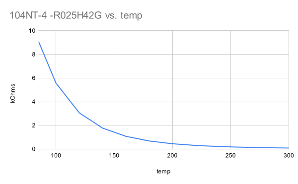
Measuring this range is difficult because the resistance of the thermistor changes a lot over the range I care about. at 25C, this particular model is 100k ohms, and at 200C it is about 1k ohms. It is very not linear, changing very rapidly at first. Thermistors are often used in a voltage divider, where the output voltage is related to the temperature of the thermistor:
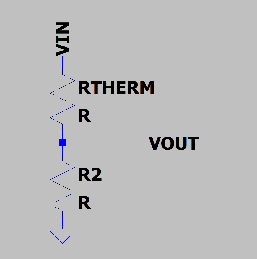
This causes a problems for my implementation because choosing other resistor in the divider causes the most sensitivity near the value where Rt=R2. That is, the temperature sensing will be easiest near where the thermistor and the other divider resistor have the same value.
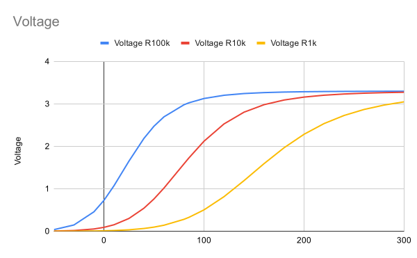
This is a chart showing the expected output of a voltage divider with three different resistor values, computed from the temperature-resistance chart plotted above. The steeper the curve, the better, since a small change in temperature will create an easily measurable output. But none of these curves are linear across the whole range that I care about, from 25-200C. Instead, the 100k looks good from 0-50C the 10k looks good from 50-120 and the 1k looks good from 120-200. At the center of each of these ranges is where Rt=R2, and the output of the voltage divider is about half the input voltage.
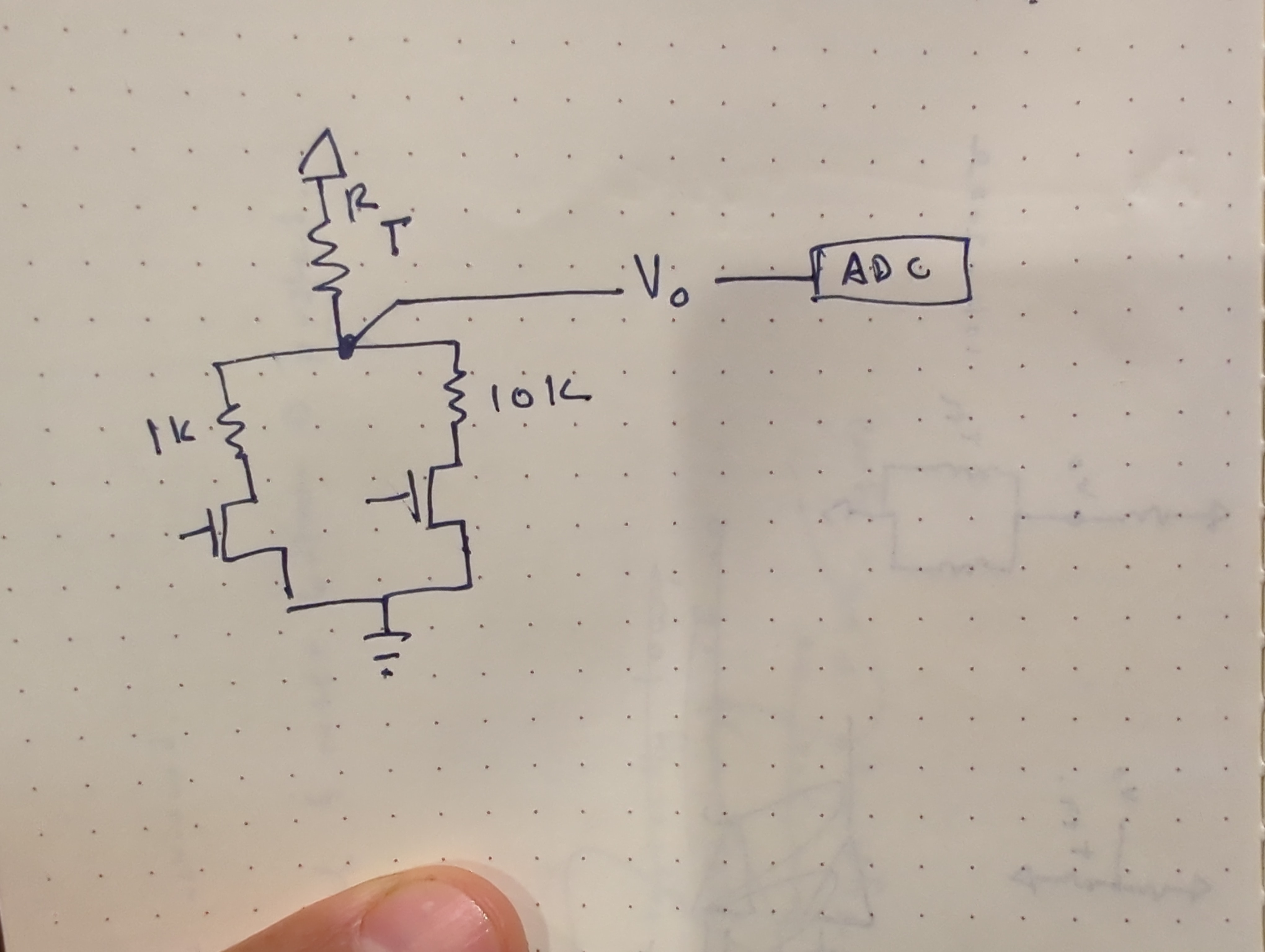
My solution was to use several different resistor dividers instead of a single resistor divider. The final implementation uses an analog mux instead of discrete FETS, and included a 100k resistor divider as well.
Calibration
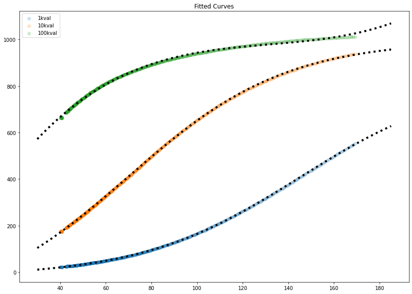
While it would be possible, through first principles and careful measurement, to figure out some mega-equation for all these components, I decided it would be a lot easier to write a script to calibrate each “channel” of the measurement. These thermistors are calibrated against a thermocouple, which was the original sensing element on the hotplate. To collect calibration data, I just measured the hotplate with the thermistor and thermocouple taped together. This produced the curves above, as expected from the simple simulation. Shown in black dots are fitted curves- the bottom two fit a sigmoid/logistic curve, and the top one (which didn’t have enough data to fit to a logistic curve easily) is fit to a 4th order polynomial. The 100k resistor values (green, top line) were pretty useless above 40C, quickly flattening out.
These curves give us a value that predicts ADC ticks for an input of temperature. The inverse is really what we are after, but that is easy to do mathematically.
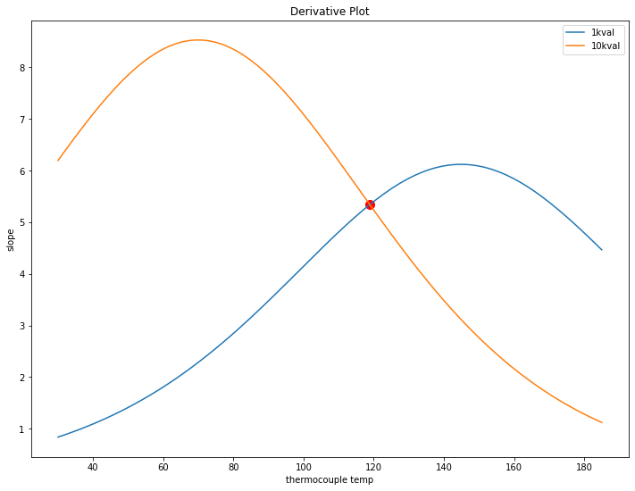
Looking at the two remaining 10k and 1k curves, the question is where to swap from one to the other. The goal is to keep the amount of ADC counts per degree C as high as possible over the whole range. This can be found by inspecting the derivatives of the fitted curves and finding where they meet (in this case, just around 120C).
This chart also shows why exactly a single value for R2 in the resistor divider would be bad. For example, below 40C, the 1k resistor shows less than 1 tick per degree C, so a 1 degree change would be hard to measure there.
Limitations
This was done with a single set of data, so it may not be accurate for all time. Taking more data in the future would be neat, especially because the python script for analyzing the data will just spit out numbers. It would be interesting to compare the calibration coefficients for various data sets to figure out how much they change, run to run. Hopefully it would be a small amount.
Solution Cost
The reason I didn’t go with a thermocouple is that the reader and the thermocouple alone would cost about $10 in parts. I usually buy multiple ICs per prototype (in case of an accident) which would cost something like $15-20 in parts. The parts for the equivalent thermistor solution cost about $2.50 per unit, which is cheaper than just the thermocouple reader IC.

One thought on “Wide Temperature Range Thermistor Use”