My beloved sola 2000 has finally, after many years of service (and after buying it secondhand) flooded. High power LED drivers and seawater do not mix well, and this light is at its EOL.
I have always wondered what was in this wonderful light, and now that its toast I don’t have any issues tearing it down to find out! There are a lot of very clever design decisions in this light, and a lot to learn.
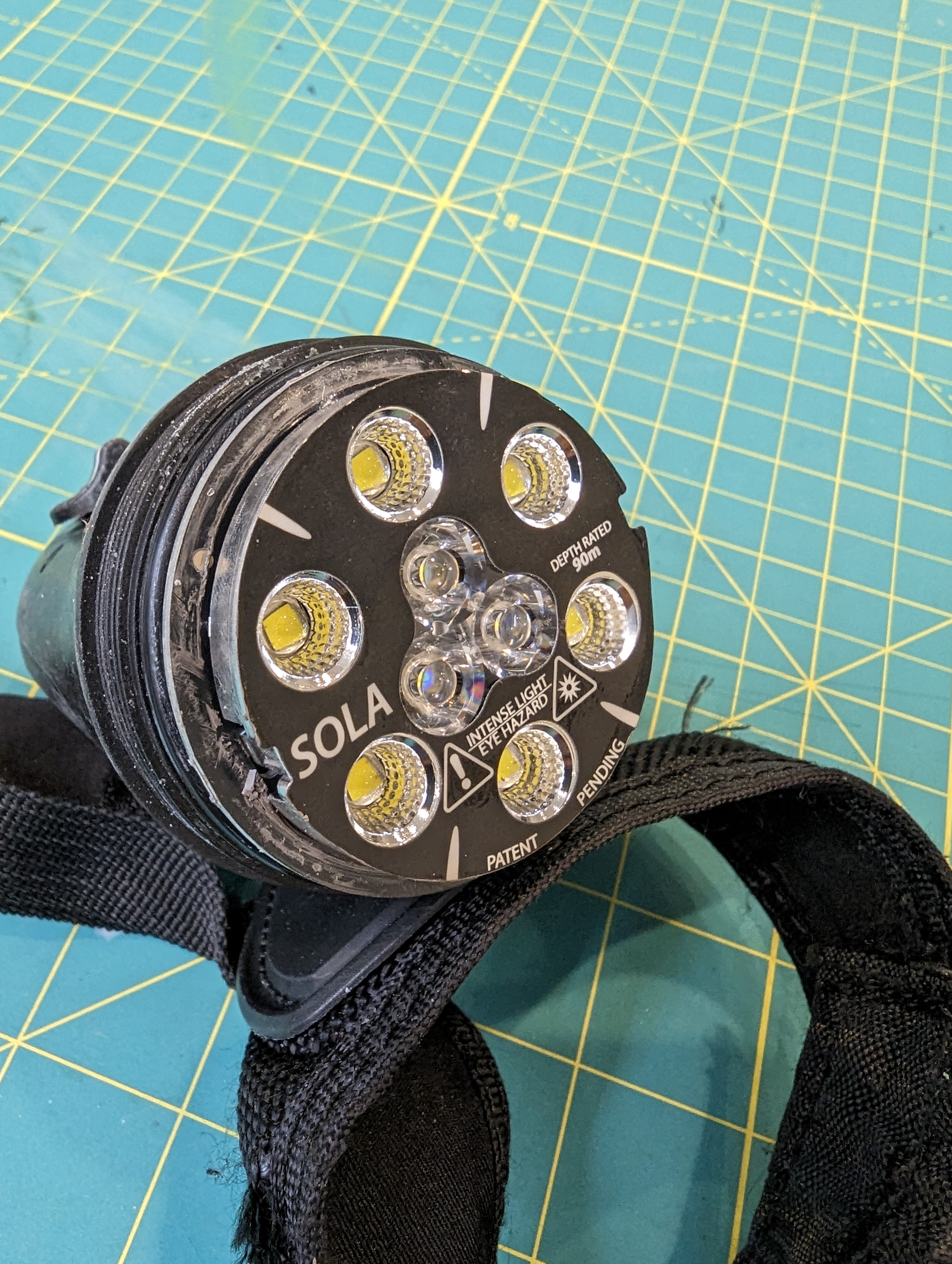
Light head
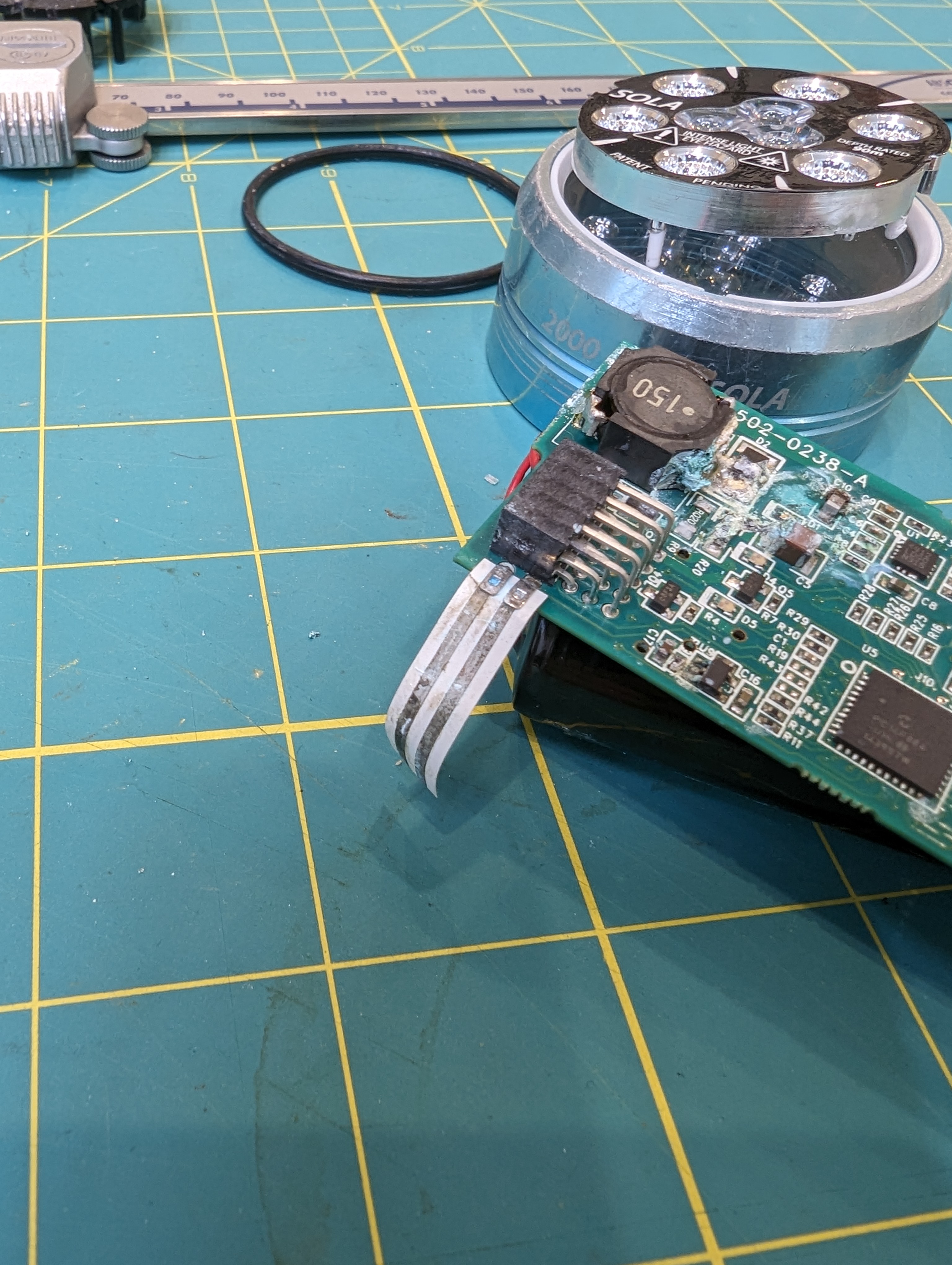
The light head has two rings of LEDS- one for spot lighting and one for flood lighting. the small inner ring of three LEDs is the spot light, and the outer LEDS are the flood light. Given the package size and general shape the LEDS, I assume the inner ones are CREE XP-E2 LEDS, and the outer ones look like CREE XM-L2 LEDs.
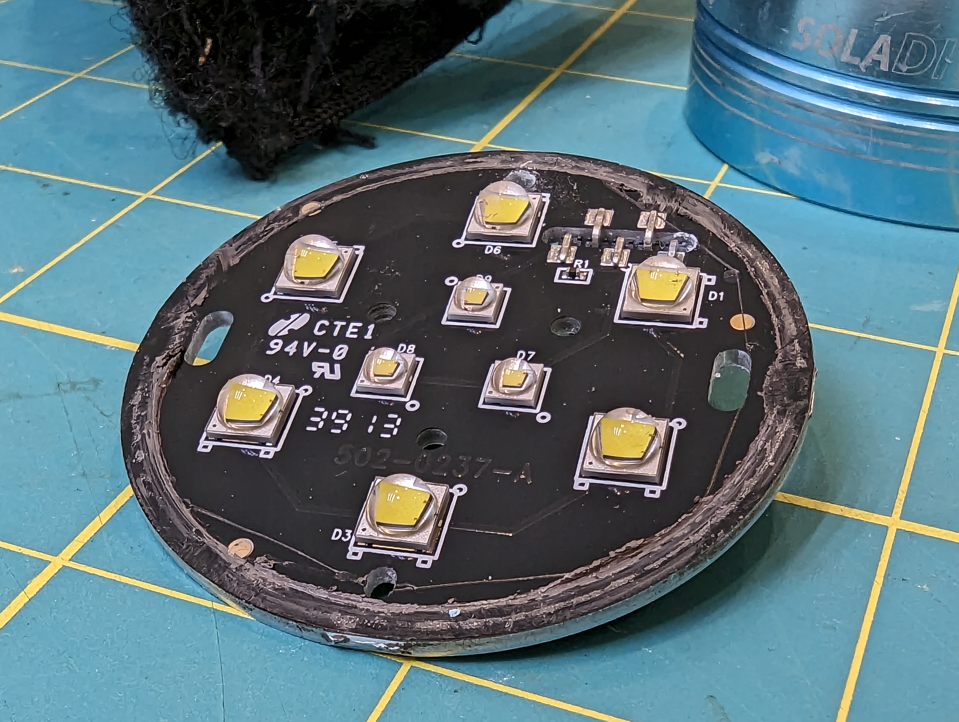
Having multiple LEDs is very smart, because LEDs run more efficiently (in terms of light per heat) at lower currents. It also spreads out the heat loading of the PFB- CREE says to estimate 75% of LED power to turn into heat instead of light- that means that a 4W LED needs to dissipate 3W of heat.
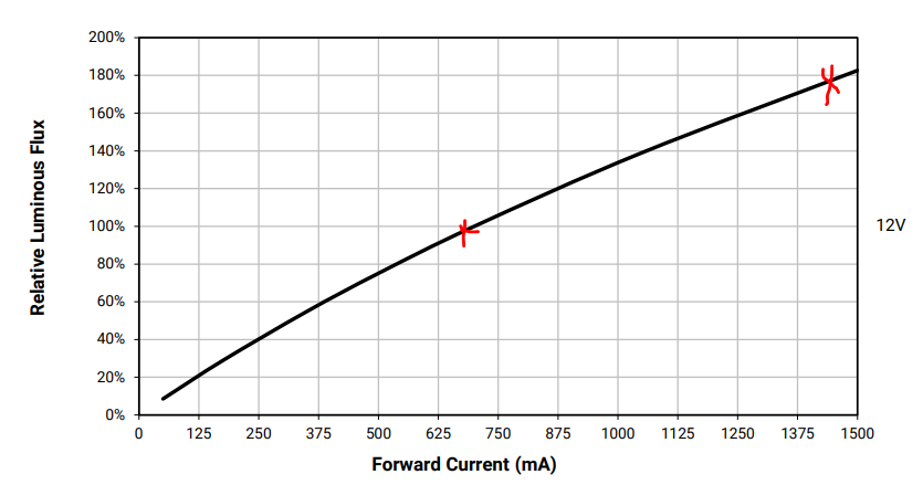
Given the stated lumen output of the light, I would guess the flood lighting runs around 9-10W, or 1A at about 9V. The ring of 6 flood LEDs probably run at about the same current (1A) but at about 18V, for an output of 18W. This means that about 7-14W needs to be dissipated. This seems to be done through good contact of the aluminum PCB with the metal ring that goes on the front of the light. If you look at the PCB photo above, you will see a smear of thermal grease along the edge.
Running multiple LEDS efficiently means spreading the heat around, especially for the radial LEDs, which are closer to the heat-sinking bezel. Its also important because the light is powered by a relatively small battery pack.
To prevent overheating, it seems like there is a single thermistor on the PCB as well. This will let the controller throttle the output when the emitters get hot.
Optics
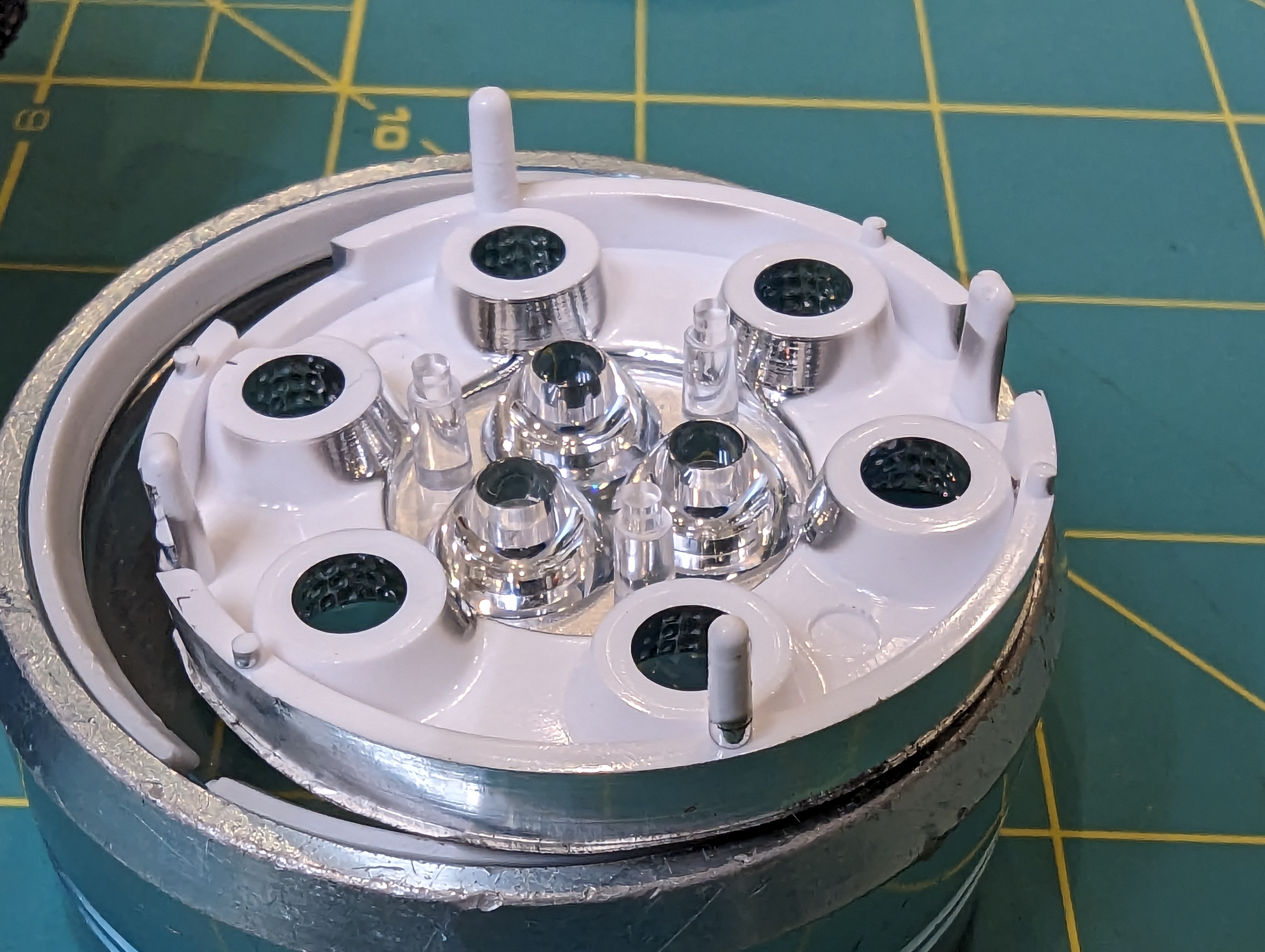
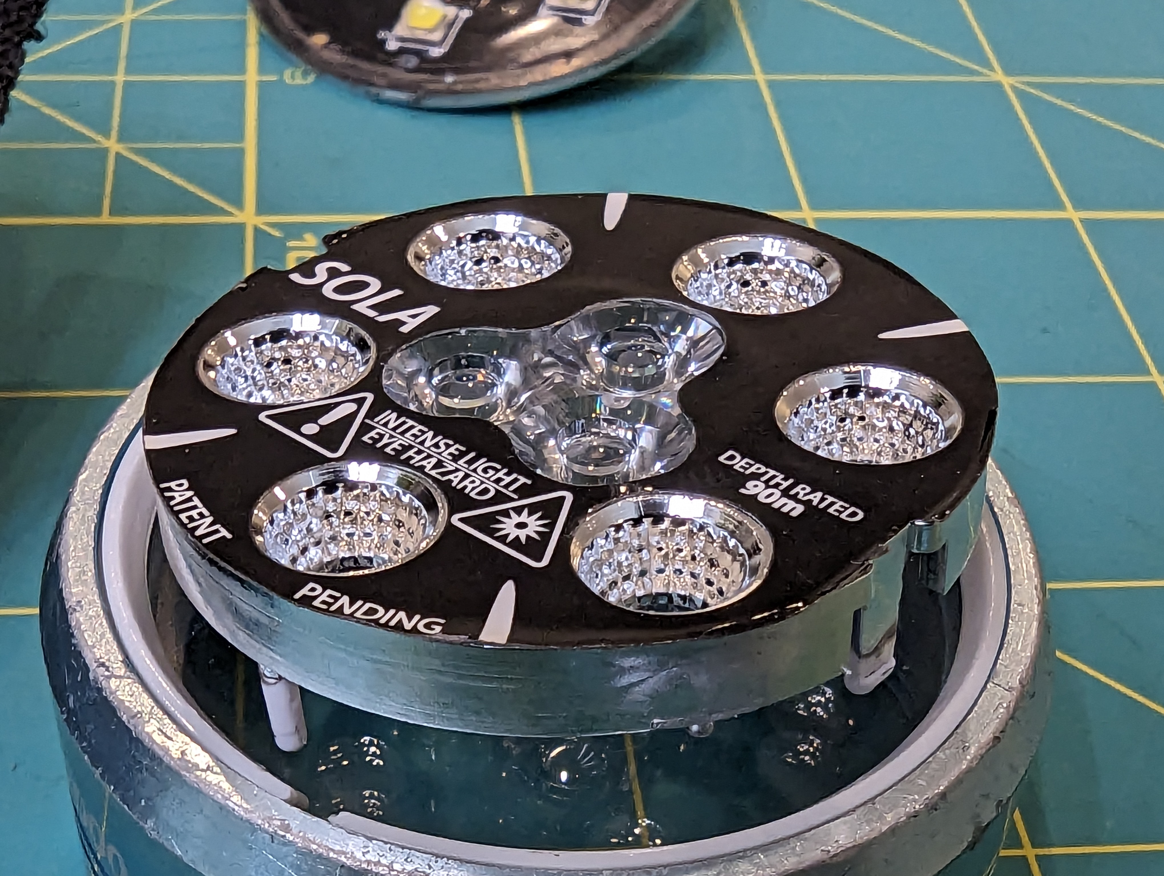
The optics look a lot like they are made by carclo (wild conjecture). There are two styles- reflectors for the spot lights, and a total-internal reflection style optic for the spot light. I do wonder if there is any attempt to collimate the spot beam to make it extra tight, by biasing the three spot beams inwards.
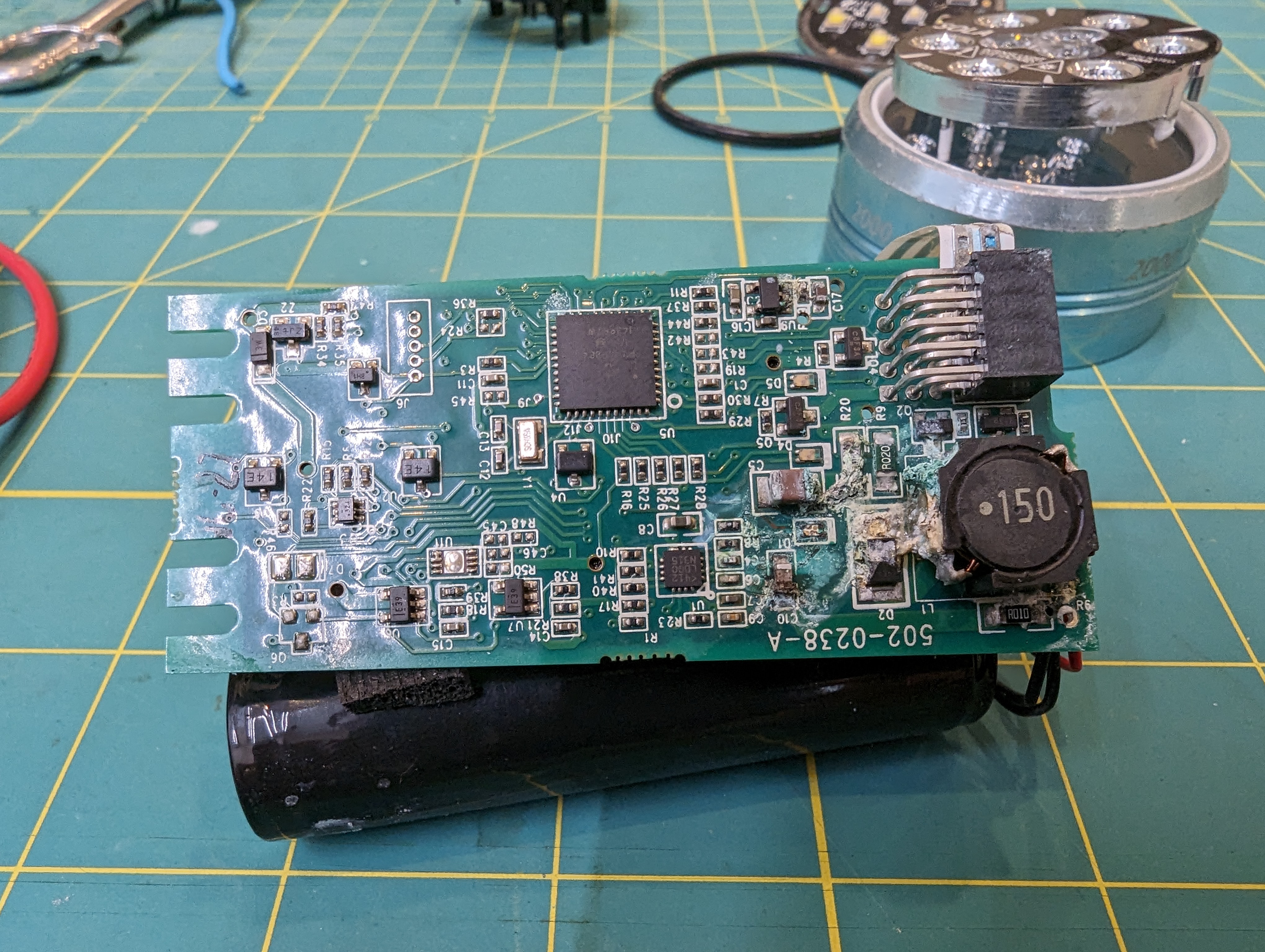
LED driver
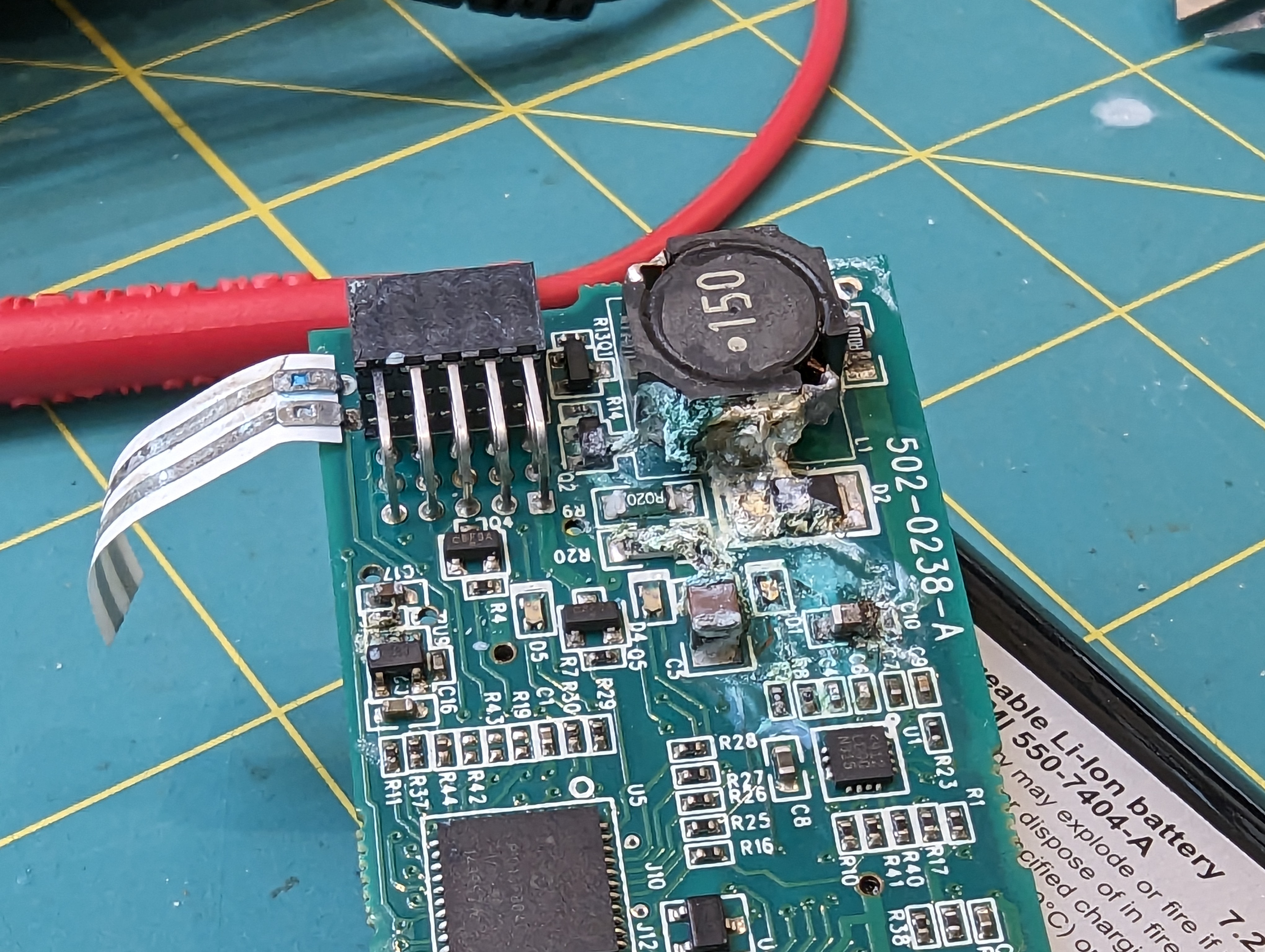
The LEDs are driven by an LT3755 wide-input rage LED driver. This driver is probably operating in boost mode all the time, since the battery voltage is too low to drive any of the LEDs. Interestingly, there is only one driver (just like in my design) but there appear to be two current sense resistors. I suspect these resistors are switched in for the spot and flood modes (on the high side, with a PFET), and then the overall brightness is controlled by PWM. This makes sense because these LEDS are probably operating at reasonable efficiency, so there is no advantage to turning down the average operating current.
As you can see, most of the corrosion/damage happened near the boost converter. It is close to where water can come in, and it is also where the highest voltages exist on the board. Seawater can cause a short between the current driver outputs, which would then tend to increase the output voltage until the current set point was reached, or until the driver maxes out or reaches some thermal limit- in other words, its a vulnerable circuit.
Flood sensor?
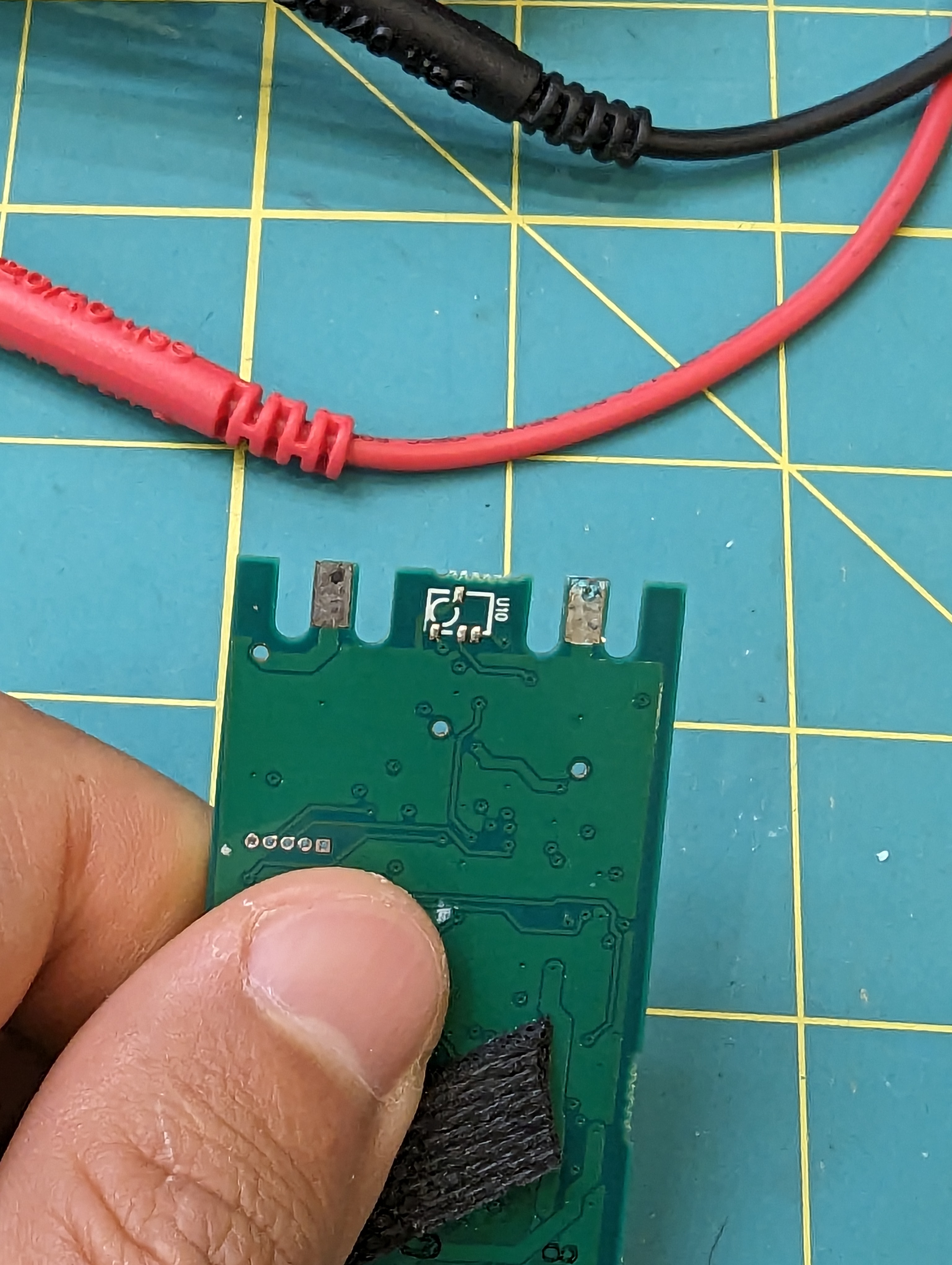
This board has something pretty unusual on it- a big floppy ribbon with conductors on one side. At first, I thought it might be some kind of temperature sensor, but I think it is a flood detection circuit- if it gets wet, it will alert the micro to shut down the led driver. This makes a lot of sense, both to protect the battery and the PCB. If the lamp is dried out after being protected from a flood, I imagine it would be just fine.
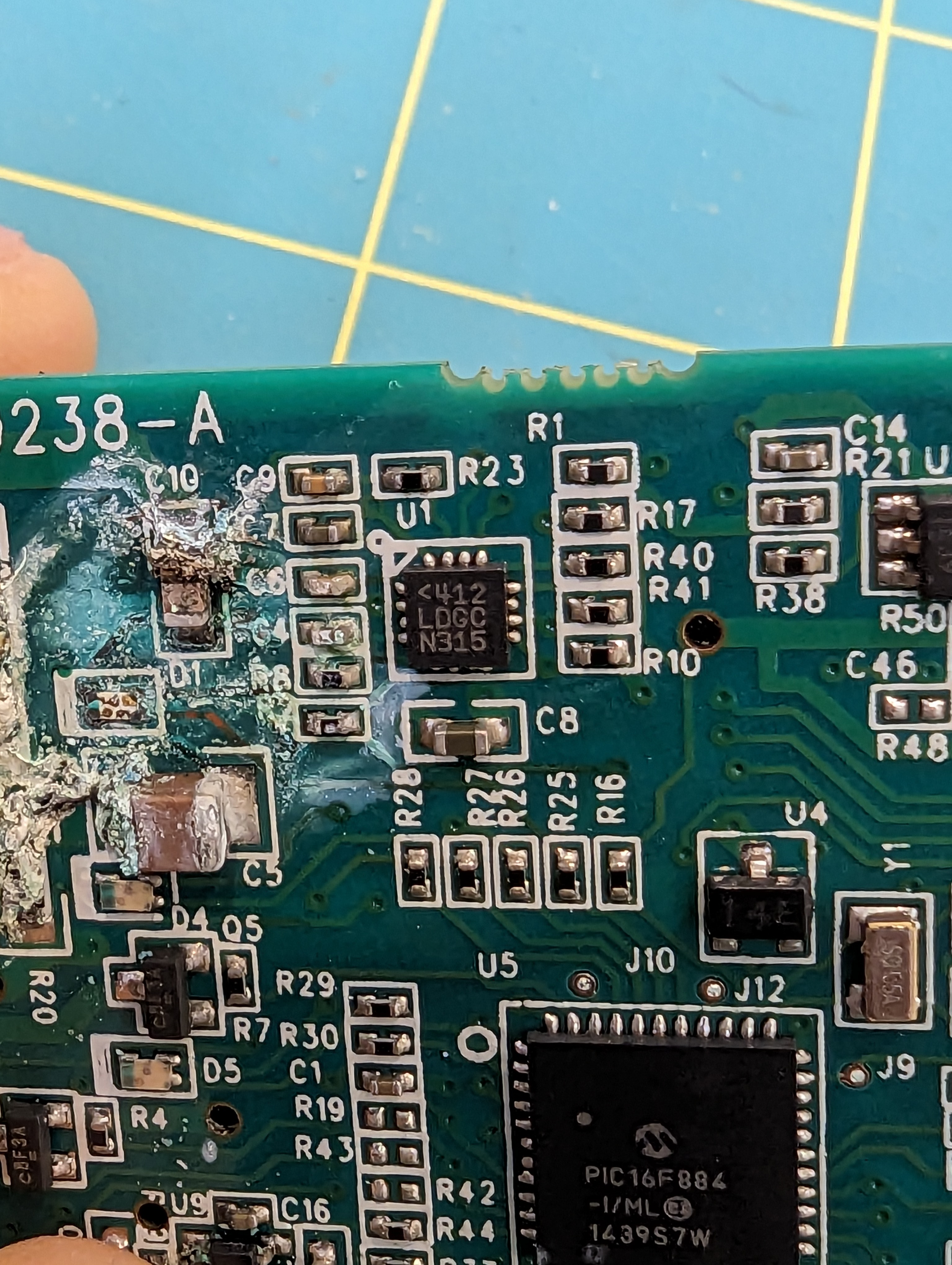
Magnetics + Micro
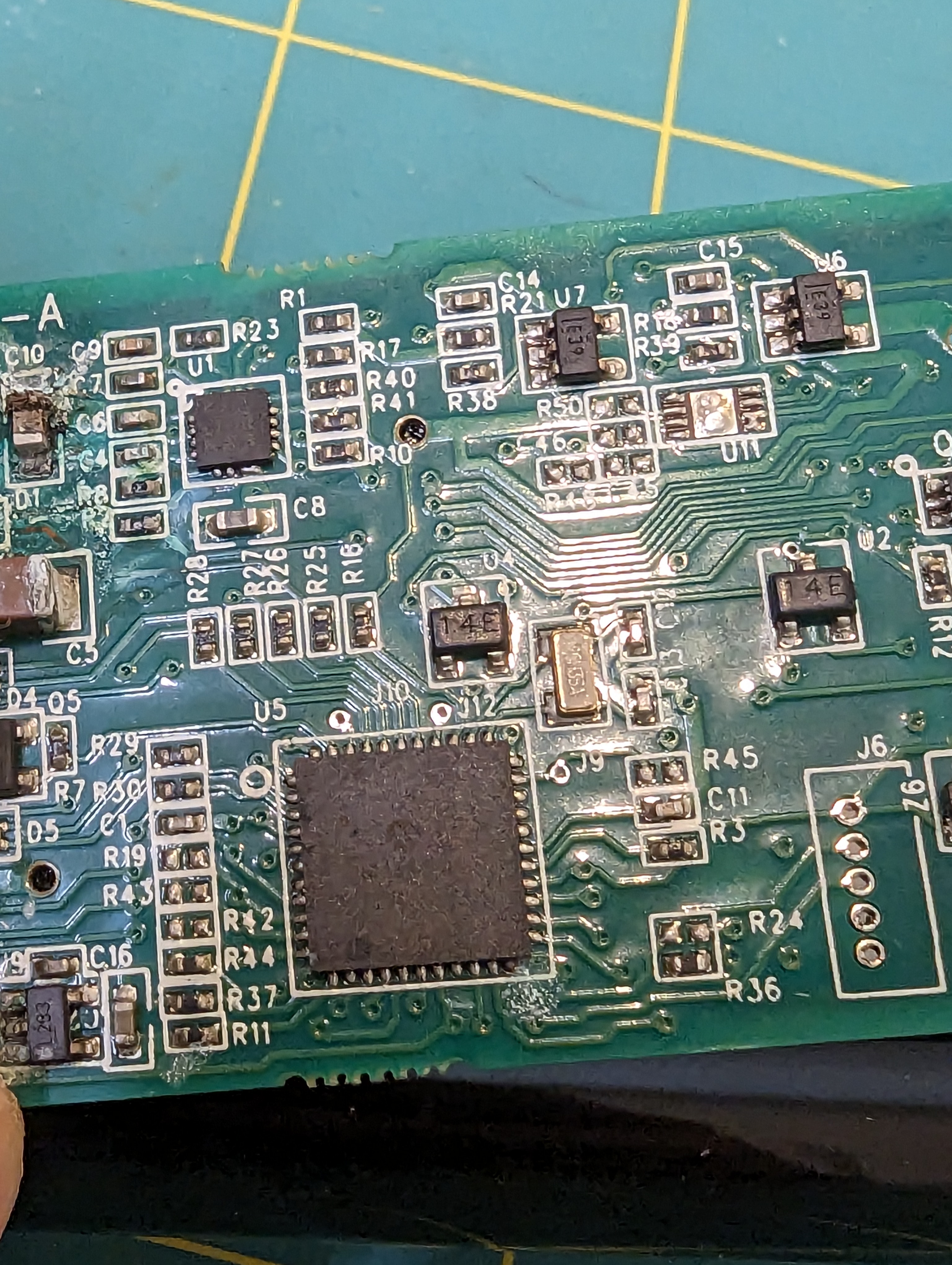
The micro is a pretty basic PIC16F884. The interface is much cooler. There are three evenly spaced IC’s marked “14E” on the PCB. I am guessing these are made (or were made) by NVE, since a lot of their ultra-low-power magnetic switches have that as a portion of the part number. This allows for control of the light without having an extra hole (leak point) in the case.
Power connections
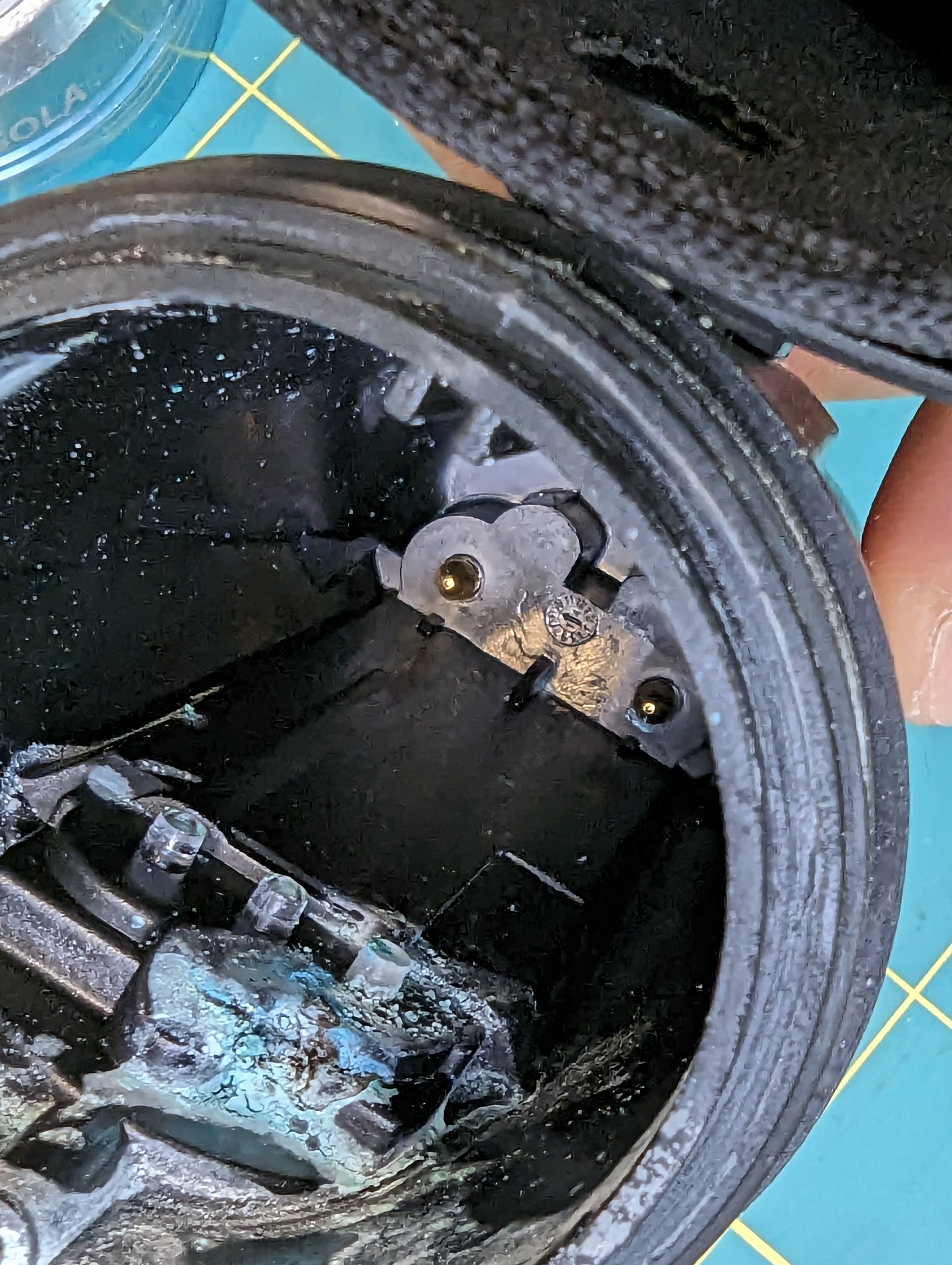
Surprisingly, the power connections are made by wedging the pcb onto the gold contacts in the back of the case. Never in a million years would I have though that this would work so well, but some clever ribs in the back of the housing push the skinny pcb cutouts/contacts onto the gold plated pins.
Autopsy
I’ve always liked the sola lights because they are “factory sealed” and there are no waterproofing components that need changing regularly. Inspection of the front oring didn’t yield any interesting results, but looking at the light pipe seal, I have some suspicions that this might be where the light failed.
The corrosion is right under this seal, although that is also the most likely place for corrosion to happen, so its not a slam dunk. However, this is a circumferential static seal, and there are things I dont like about it.
Specifically, the surface finish of the light pipe is not very smooth on the contact area of the oring (difficult to photograph), and the whole light pipe can rock gently (although this is somewhat prevented by the bezel). The bend radius of the oring is also pretty tight compared to the diameter. The radius is about 2x the diameter, where the best practice would be about 6x the diameter.
Obviously this is a fine design, given that this light has lasted many many years. That said, I am suspicious of this seal.
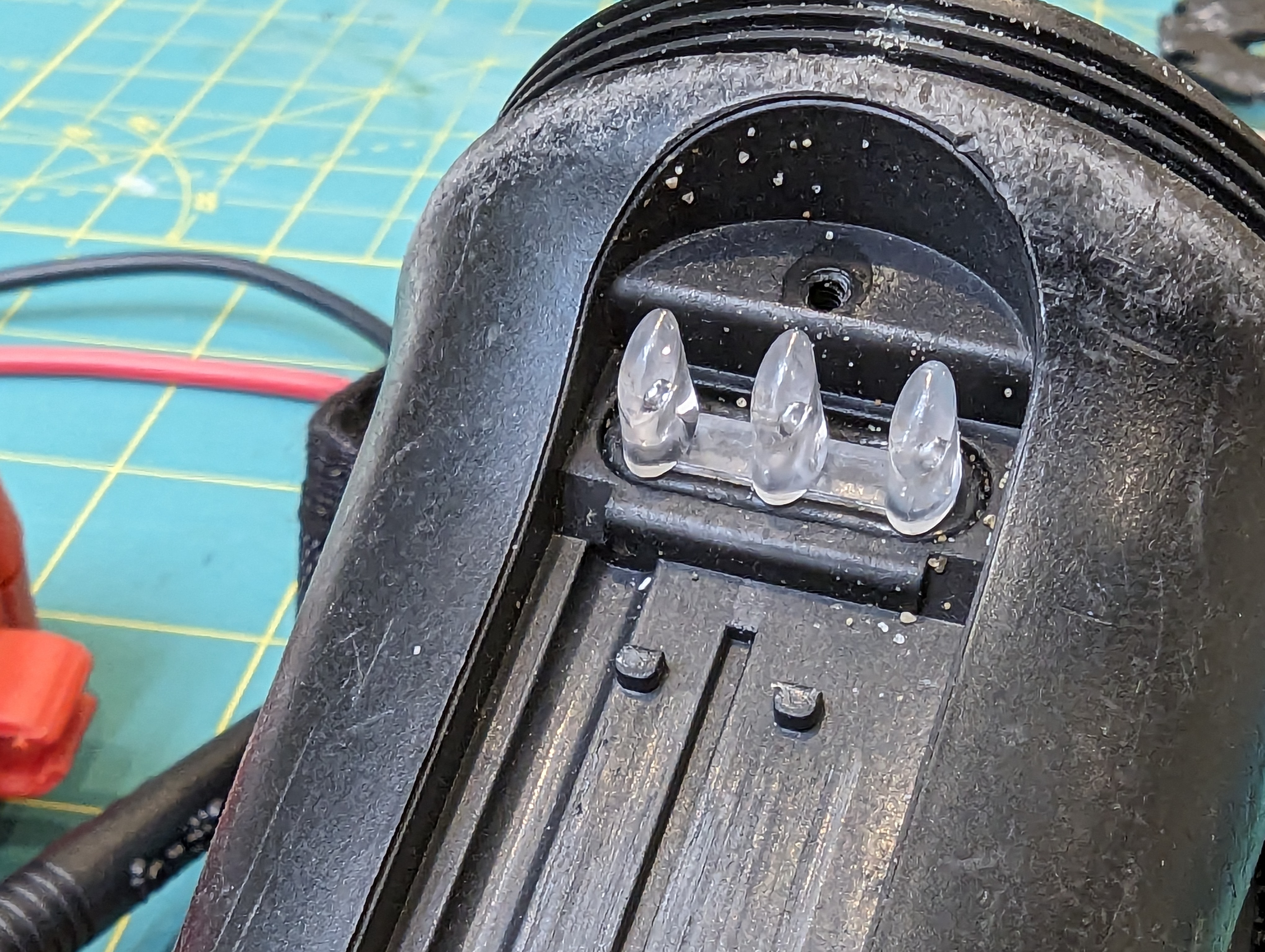
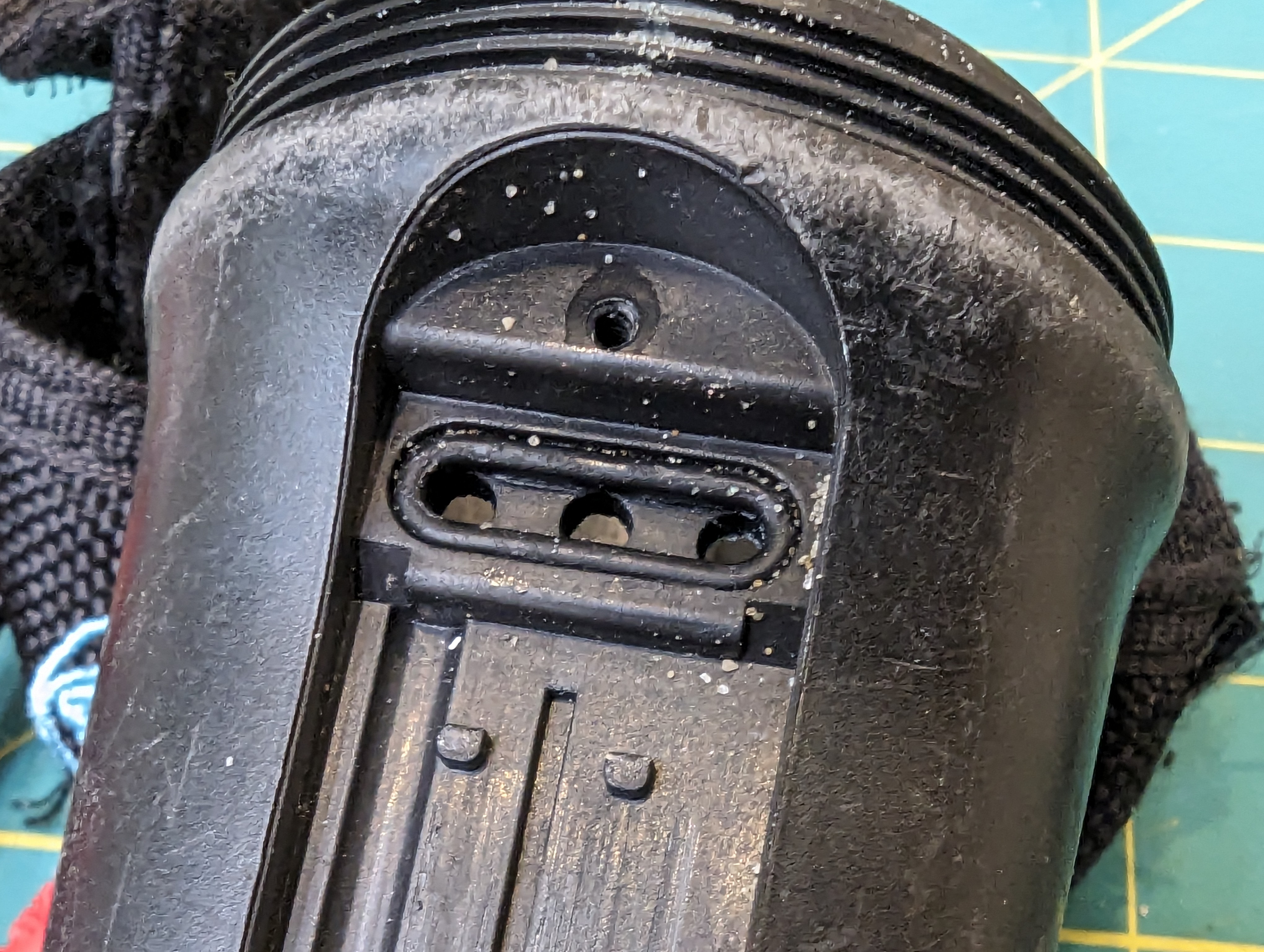
Closing thoughts:
This light is pretty tidy from an engineering prospective, and it was a great dive light. I am still curious about what is shared between different models- how is it different than the sola 1500? from the spot lights (the driver here could easily drive a COB)? How did they reuse parts between the designs? And what on earth is that funny three-tier connector for (different models?).
I won’t be getting the answers to these questions but its fun to see what made this thing tick for so long.

One thought on “Sola 2000 Teardown”