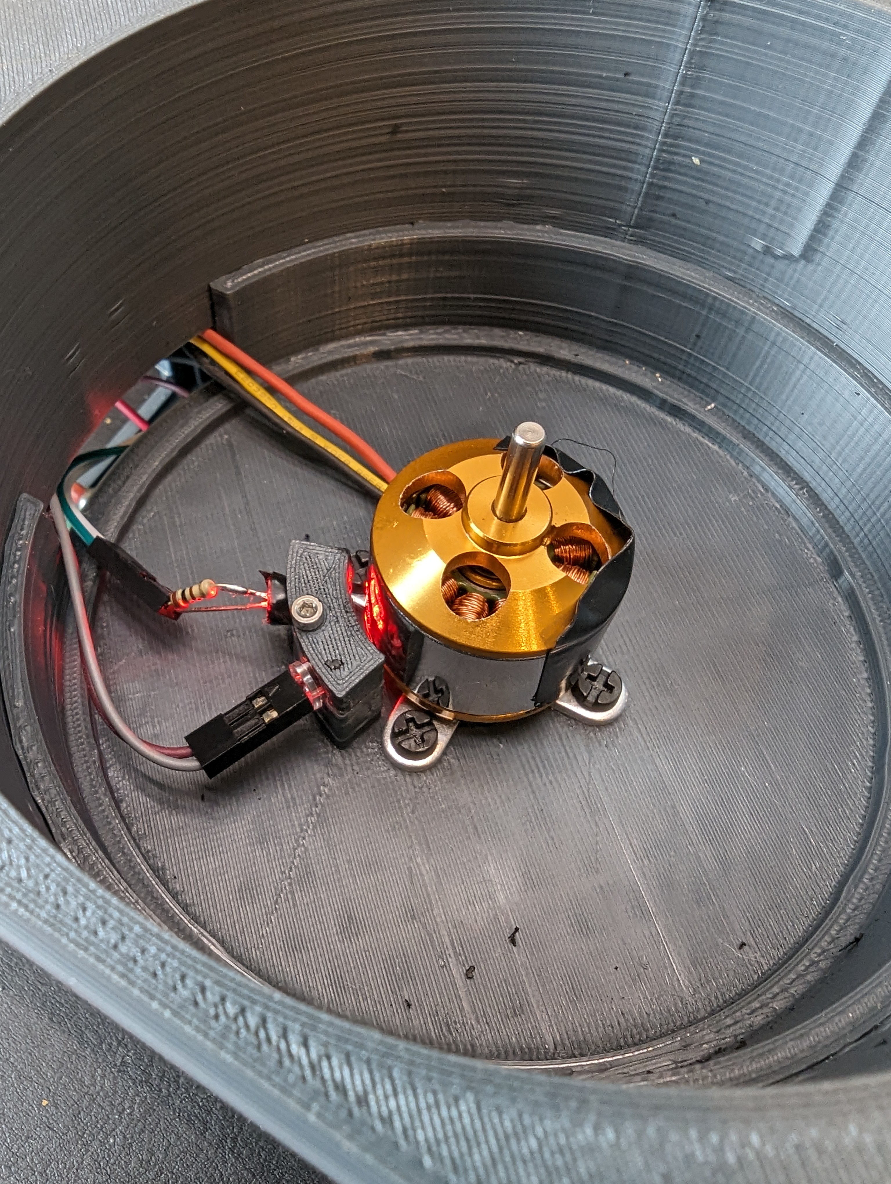
With the tachometer done, the next step was to get the ancient BLDC and ESC wired up and figure out how fast they were spinning. I know that the motor spins very fast but I really didn’t know how fast it was. It turns out that the speed is mostly too fast.
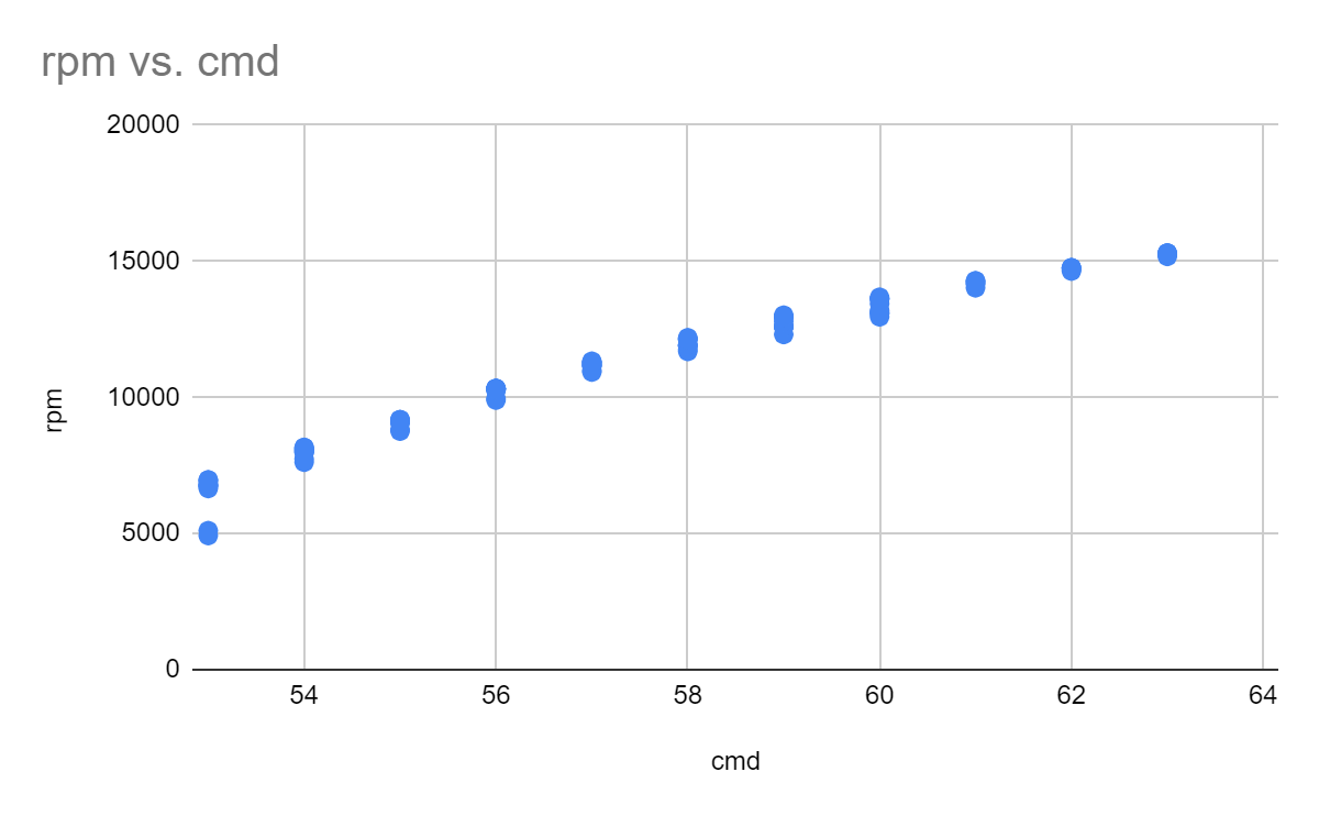
Here I plotted the RPM vs input command, which is basically in “hobby servo degrees” since that is how the ESC expects to get commands- a pulse every 20ms where the width of the pulse corresponds to…something. I mostly care about speeds between 5-10k, which gives me about 4 settings. I suspect that by decreasing the voltage of the power supply, I could decrease the minimum speed by limiting the free-run voltage across the motor.
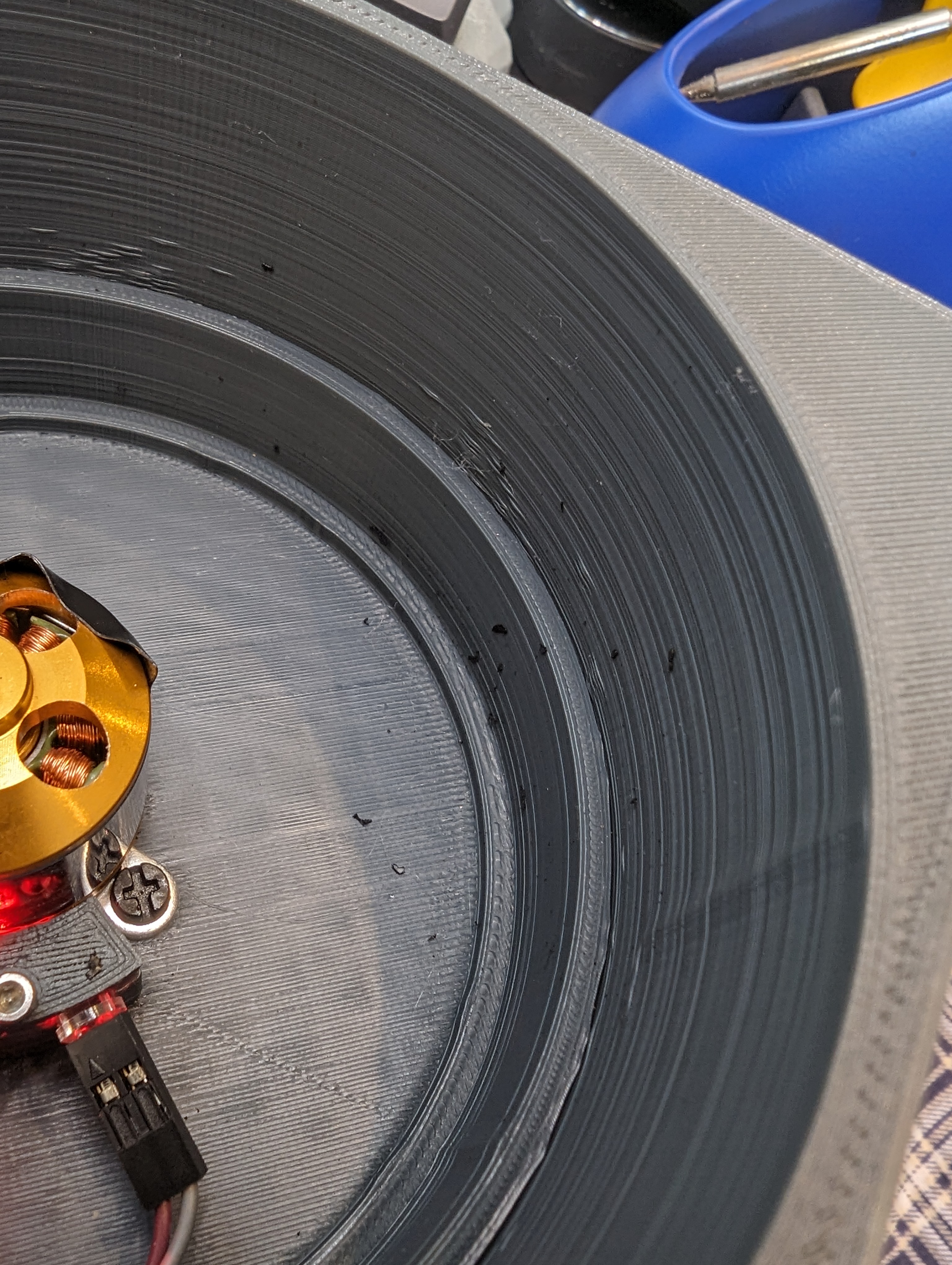
As I said, its not clear exactly what the mapping is from pulses to rpm, since I don’t really know how the controller works- is it closed loop? is speed control achieved with voltage limiting, or is there actually feedback? Right now it doesn’t matter since my goal is just to make things spin fast. As you can see here, the motor spun fast enough that the tape I was using as part of the encoder ripped itself off and disintegrated all over the inside of the container.
Next Up: A PCB
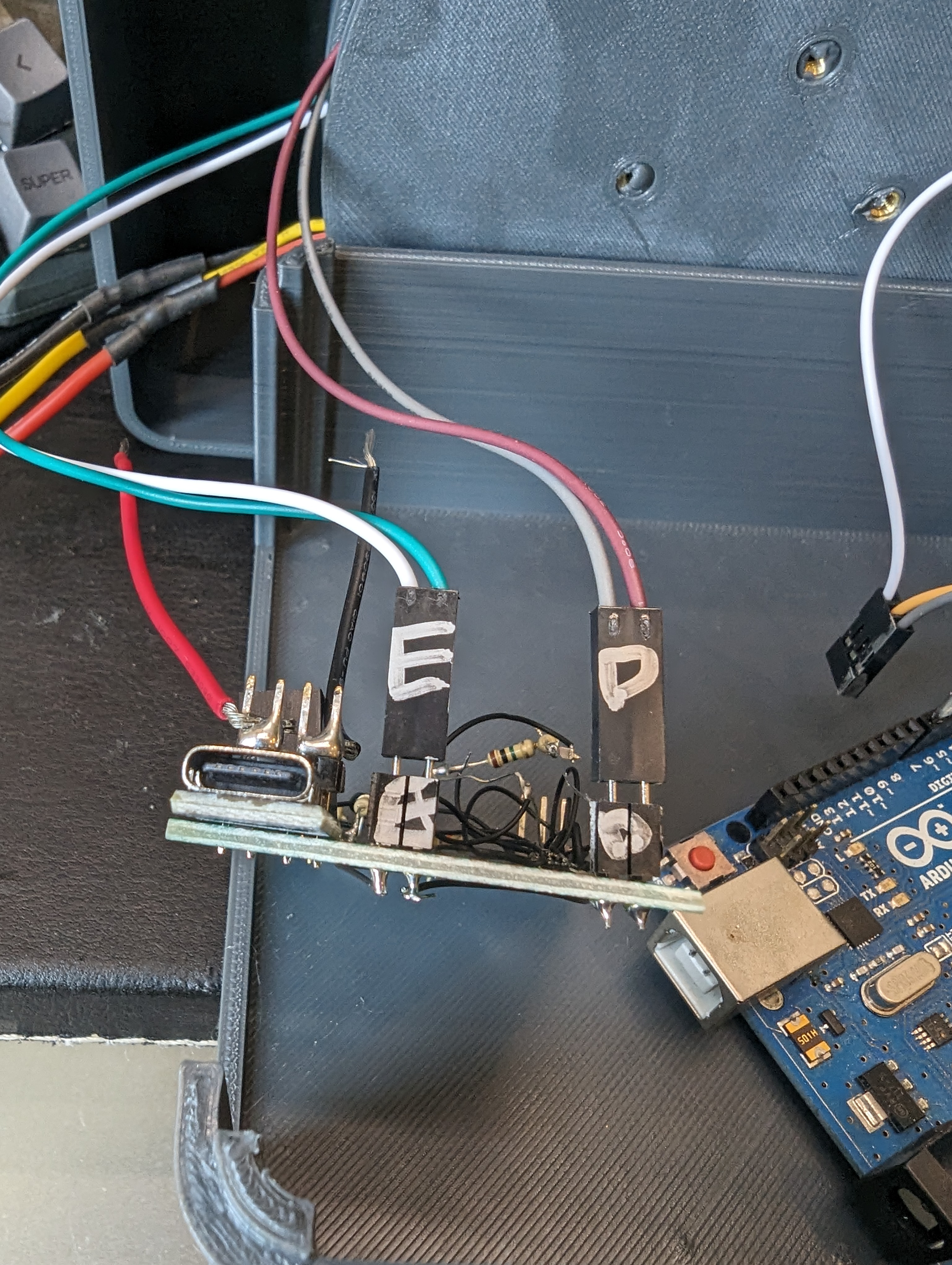
Based on a lot of really annoying fiddling and having parts get de-soldered during assembly, I have decided I really need a PCB for this project to prevent it from self-destructing by vibrating my deadbug soldering apart. A display, and maybe some buttons would help make it fully usable.
