POEJect 3 AKA “The V-USB”

Check out the downloads page for a barebones USB script that lets you send commands over USB, and some basic code you can throw on an AVR chip to try this out!

Laser Turret!

I am currently taking a class called “The Principles of Engineering”, AKA POE.  The name of the class is very old-school and almost baroque, but really what it boils down to is twenty engineers of various flavors and a professor sitting in a room for a few hours a week.  There are no lectures, there is next to no instruction, and only four assignments.  the first three are based on a PIC microcontroller, and the last assignment is an open ended project where students in teams of 4-5 build something with a “significant electrical and mechanical component”.

POE lab three “One Button, Two Blinky Lights, and the USB” was designed around using a PIC.  Naturally, my team took this to be a challenge.  Out of dislike for MPLab (PIC IDE), PICs, and generally being iconoclasts in POE, we decided to forgo the pre-written USB implementation on the PIC, the python that interfaced with it, and the GUI framework that was supplied to us, in favor of doing it all ourselves.  We decided to do this, and then we waited until the day it was due to start working on it.

With t minus 10 hours, we decided to make a laser turret.  Our reasoning was:

  1. We have servos
  2. We have a laser
  3. ????
  4. Profit!

It was around 12:30 when we got started implementing V-USB, PyUSB, a TKinter interface, and some AVR C (windows users: winavr) code to run the servos.  I would like to give a huge thanks to Kevin Mehall here, who is a massive baller when it comes to things like V-USB and microcontrollers for helping us out with some bugs we were having.  This writeup is so that you all don’t have to go through the same stuff we did to get V-USB working.

Implementing “The V-USB”

V-USB is a Virtual USB port for AVR chips.  This lets you talk to them over USB, or in this case, to make them into a USB Device.  It’s a beautiful thing, but is totally a hack.  This project is a good example of the simplest thing you can do with V-USB, which is send some data to the device with a control transfer.

Start by making a directory for your project.  The next step of getting V-USB to work is getting the header files from the downloads page of V-USB.  For those of you on linux machines, just tar -xzfv filename.  Then copy the files into the project folder.  You will also need a makefile.  You can get a makefile from the examples on the V-USB website, or you can get the one I used (originally from the V-USB website) on the downloads page, so you don’t have to download the whole thing.

Include the usbconfig.h, and usbdrv.h in your file.  To get this to work, the file that you will have to play with to get V-USB working is called usbconfig.h.  Find it, and open it in gedit or bluefish or your text editor of choice.  MAKE SURE IT IS IN USBDRV.  All of the options are described very clearly, but the ones that are important and that you should look at first are:

  • All of the hardware config
  • Optional hardware config
  • #define USB_CFG_HAVE_INTRIN_ENDPOINT    0
  • #define USB_CFG_IS_SELF_POWERED         0
  • #define USB_CFG_MAX_BUS_POWER           400
  • #define  USB_CFG_VENDOR_ID       0xc0, 0x16
  • #define  USB_CFG_DEVICE_ID       0xFF, 0xFF
  • #define USB_CFG_VENDOR_NAME     ‘A’, ‘L’, ‘O’, ‘U’, ‘I’, ‘E’, ‘1’, ‘4’
    #define USB_CFG_VENDOR_NAME_LEN 8
  • #define USB_CFG_DEVICE_NAME     ‘P’, ‘O’, ‘E’, ‘J’, ‘e’, ‘c’, ‘t’, ‘3’
    #define USB_CFG_DEVICE_NAME_LEN 8

The hardware config will depend on your circuit, and I will talk about that in a moment.  The other options (in order that they are listed) make it so you have an endpoint 0 (default), tell the USB controller that the device is powered by your USB port, set the max current the USB port will provide, set a vendor ID (I used the default), a device ID (anything can go here), a vendor name and length of name, and a device name and length of name.

Below is a diagram of the circuit I used.  It is good for illustrating how to set up usbconfig.h based on your hardware, but you might not use the same AVR so your mileage may vary.

The Secret Knowledge Arduino uses V-USB! the connections to Pin 1 are not needed for V-USB.

My hardware file looks like:

#define USB_CFG_IOPORTNAME      D

As you can see, we are using pins PD2 and PD3 for D+ and D-.  The port we are using is D, so we define USB_CFG_IOPORTNAME to be D.

#define USB_CFG_DMINUS_BIT      3

#define USB_CFG_DPLUS_BIT      2

These tell V-USB which pin on the chosen port (D) D+ and D- go to.  Note, D+ goes to PD2, which is pin 4.  We use the name of the port not the name of the pin, because the C code accesses the pins by port, not pin number.

#define USB_CFG_CLOCK_KHZ       (F_CPU/1000)

#define USB_CFG_CHECK_CRC       0

These are set correctly.

#define USB_CFG_PULLUP_IOPORTNAME   D

#define USB_CFG_PULLUP_BIT          4

This sets up a pullup resistor so we can connect or disconnect the device with software commands.  The resistor is the 1.7 K ohm resistor in the schematic.  If this is not set, that resistor should be connected to D- and 5V.

Bad breadboarding! Do not do!

One last thing that I did, specifically for this hardware, was calibrate the internal RC oscillator so that we didn’t have to use an external crystal.  This is achieved by copy-pasta into usbconfig and into your C code.  documentation can be found here if you are interested: http://vusb.wikidot.com/examples.  Look for “Clocking the AVR from the RC oscillator with auto calibration” on that page.

Now that that is done, you should be able to make (just go to the folder in the terminal and type make) your project.  If you get some error about not having a clock frequency (F_CPU) add this line “-DF_CPU=12800000” to the COMPILE line in your makefile.  Replace  12800000 with your clock frequency.

Now you probably have some bug complaining that “usbFunctionSetup” is not defined.  We are going to need to define this, because V-USB needs this to be set up to function.  This implements the ability to perform a control transfer, which is needed to set up anything over USB.  My code looks like this:

usbMsgLen_t usbFunctionSetup(uchar setupData[8])
{
usbRequest_t *rq = (void *)setupData;   // cast to structured data for parsing
on=rq->bRequest;
xval=rq->wValue.word;
yval=rq->wIndex.word;
return 0;

}

This is just an example of totally abusing the control transfer.  In this project, I just wanted to send a few bytes to the AVR to tell it how to control the servos and the laser, so I used the values for bRequest, wValue, and wIndex to hold the information.  These are just part of the control transfer request, which has these arguments:

(bmRequestType, bRequest, wValue, wIndex, wLength)

These are sent from the computer (from a python program) to the AVR.  bmRequestType tells the device what kind of request it is, bRequest is the name of the request, and wValue, wIndex I (ab)used to send data, and wLength, is the amount of data that is supposed to be sent over the control transfer.

Normally these are actually used to set up a data transfer, but I used them to send over a couple bytes of data in bRequest, wValue and wIndex.  Here is an example (from my python interface) of a request:

dev.ctrl_transfer(0x40,1,0,0,None)

This means that it is an device to host transfer (0x40 is the number for a vendor specific control transter) and that the request number is 1, and wValue and wIndex are 0.  The last argument is None, because no data is being sent, but this is python (pyUSB) specific.

Implementing “The PyUSB”

Once I had the hardware usb code for the chip compiled and working, I started to work on the python that would talk to the chip.  I had a lot of help from examples from Kevin, because the sum of the documentation for PyUSB that I could find was about 4 pages, and it was not very specific or well written.  The important lines (for the whole dang thing, see downloads!) were:

dev=usb.core.find(idVendor=0x16c0, idProduct=0xFFFF)

This makes an object dev that is attached to a specific Vendor and Product id, provided usb.core.find can find it.  If it can’t, you should catch that error with an if statement that looks something like “if not dev:”, or “if device is none”.

the other important line is:

try:
dev.ctrl_transfer(0x40,laserState,int(x),int(y),None)
print(‘laser cannon enumerated’)
except usb.core.USBError, e:
print(‘exception’)

This tries to send a control transfer request out, and if it is successful it prints “laser cannon enumerated”.  If we run into some sort of error, it prints “exception”, which lets us know our last command didn’t go through.  This is useful for debugging, but once it was buried under the TKinterface, we commented those commands out.  This try…except block is important because without it, if the transfer gets interrupted for some reason, the python program will freak out and stop working.

Again, if you want to get your feet wet, I have put some basic code on the downloads page to play with, modify, and learn from.

Secret Knowledge Time Vol III: Tiny Computer Time

The third week of secret knowledge we decided to move in the microcontroller-hat direction.  This means that we needed an easy to learn platform like an arduino, but we also needed a cheap to buy platform like a raw AVR chip.  Kevin came up with a solution:  a “five dollar” arduino (git here).  The five dollar arduino is a bootloaded AtMega328P.  This means that it is first programmed with the bootloader by a normal programmer (a AVR dragon, STK500, or usbtiny).  Then, it is put into the circuit below, and connected to a computer.  When the button is pressed it runs the bootloader code for 28 seconds, which allows the user enough time to press the upload button on the arduino IDE to upload code to the device.  After 28 seconds, the chip boots into the user code.

We expected a lot more to get done at this secret knowledge time.  We even wrote up some arduino tutorials to go with the hardware.  Unfortunately, we hit a few snags in actually getting all the devices built and programmable.  This may be due to our (lack) of structure; we mostly just give out a handout and parts and expect people to do things on their own while we stand by to help.  Unfortunately, there was a lot of confusion about what that was exactly.  We wanted to avoid sitting them all down and showing them how to do it piece by piece, because that tends to bore and frustrate people.  A good middle ground might be a video tutorial, but that takes a lot of effort to create.

The amount that people got done this session was varied.  There was one group who got most of, but not all of their arduinos working by the end of the session.  There was another group that successfully made and tested several cool tri-color LED display programs based on novel analog input devices, like potentiometers or CdS cells.

Without a doubt, this session was a huge success.  30 (+/-2) students showed up, and as many Arduinos as we could give out were given out and built.  Hopefully over the next few weeks we can develop some sort of path to teach people how to and when to use a microcontroller.

Secret Knowledge Time Vol II: Servos

For documentation on what the activity was, go here (link not active yet).

This Secret Knowledge Time was all about…what we did last week, but slightly different.  At this point, we hoped to gather everyone who wanted secret knowledge, catch people up on what we had done last week, and to stall for time to figure out how to introduce them to microcontrollers.

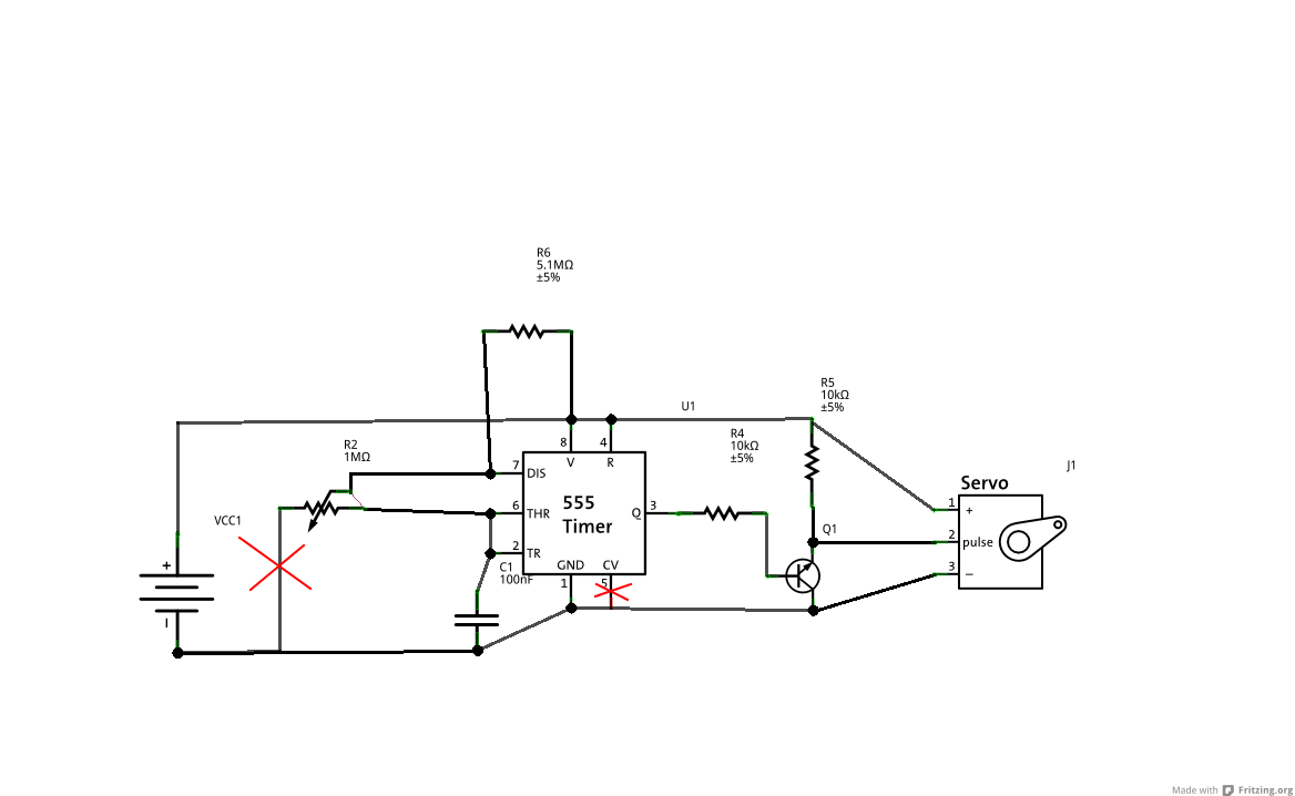
This week we made the same 555 circuit, but with a twist.  The output from the 555 was inverted and used to drive a servo (Note: the output had to be inverted because the minimum duty cycle of a 555 is 50%, and the duty cycle we needed was 10%.).  I found a few diagrams online, finagled the resistance values into something we could supply from the stockroom, and the built and tested the circuit.  It worked!

Again, errors are marked with red Xs.

However, our circuit diagram was flawed yet again.  Despite testing the circuit, we had not tested our diagram.  Fritzing drew several lines that we had deleted at some point, but did not technically connect them, because there was no large black dot indicating a connection.  This led to confusion in both myself and the people running the activity, and the people building the circuit.  This time the corrections and things that we had to yell out were:

  1. Corrections to the circuit diagram
  2. What the leads of the servo were (GND, V+, and Signal)
  3. What resistor went where
  4. How the pins on the transistor correlated to the pins on the schematic
  5. How to hook up the potentiometer

With all that resolved, most of the people got the circuit working in about two hours, played with it, and went home.  We got less feedback forms this time, indicating that we needed (and still need) to implement some new kind of feedback.

We had several improvements over the first SK this time.  We had acquired additional 5V power supplies.  We asked Sasha to help us again.  We improved the handout to include background information on what we were doing, and we even had a pretty good slightly better circuit diagram.  The problems we ran into were mostly in explaining the components, in which really is based on the problem of sexy vs. critical.

The sexy vs. critical problem is going to be another theme in TSK.  Some information or skills are sexy, cool, or desirable.  Things like reading brain waves, or blinking LEDs, or making a robot are sexy.  Things like understanding ohms law and how the oscillator in a 555 works are less sexy, but in some cases that knowledge can be critical to doing the cool thing.  The problem is that to get people to show up, you need to promise cool things in a short amount of time, but to achieve that, people will need to know a few critical and unsexy things.  This turns into a chicken and egg problem.

Our solution is just to throw the critical knowledge at them as they do cool stuff.  Sometimes this comes across as being unprepared, but it is almost easier to just do it on the fly as opposed to spending hours typing up detailed explanations of every component.  It also limits how “theory” we can be.  We do not want to be “too damn theory”, which is easy to have happen in a writeup that we are trying to make into a complete, definitive document on a part or subject.  It’s hard to tell where to stop; my best estimate is that a page or half a page is probably as much as anyone needs to know, and that is something that might be handy to have as a reference for TSK.

Overall, TSK Vol II: Servos was a success.  The feedback was mostly the same, but we did have a big question hanging over our heads at the end.  People kept asking:

What’s next?

We thought that was a pretty good question ourselves.

The Secret Knowledge Vol I: The Time is Now?

This is a reflection and analysis of how the first Secret Knowledge went.  If you want the (polished) version of our actual activity, go here (link not active yet).

A few weeks ago, an email went out to the entire freshmen class of Olin College, aka “Students-Class of 2015”.  The email was an invitation to learn “all the Secret Knowledge that they required”, if they would only come to the fourth floor (our secret lair) at 7:00 PM on a Friday.  I expected maybe 10 people to show up.  Neal and Kevin were less optimistic.  In the end, we decided to print five copies of the handout we had prepared, and gathered up enough parts for five people.  When 30 or so people showed up, we were both shocked and unprepared.  Who knew that people wanted secret knowledge?

The first Secret Knowledge activity was based around a 555 timer.  The goals of the activity were:

  1. Do something cool, and novel
  2. Learn to do something

We achieved both goals, but not entirely successfully.  The cool thing that we did was blink an LED.  We did this by setting the 555 timer up as an astable multivibrator, or in layman’s terms an oscillator.  The 555 directly powered an LED.  The frequency of the blinking was variable when one of the resistors was exchanged for a potentiometer.

The goal that was not achieved 100% was the “learn to do something” goal.  First I will explain what happened, and then explain what went wrong.

Even though we had plenty of components for everyone, we did not have a 1:1 ratio of person to breadboard.  However, the real bottleneck to having each person actively prototyping and debugging their circuit was power.  We didn’t have enough time to get 30 of one type of power supply, let alone 30 of any power supply, so we had about 6 power supplies of different types scattered around the room, ranging from computer ATX power supplies, to modified wall worts, to powered breadboards.  We also made some slight errors in our handout for the activity.

Red lines or Xs indicate errors or omissions from handout…Oops!

We did account for people not knowing how to use a breadboard, which is why we included the diagram.  However, the combination of the two diagrams were nearly useless because the students didn’t know the convention for numbering pins on an IC, and so they couldn’t correlate the numbering on the European-style schematic with the breadboard sketch (made in Fritzing).  A similar problem was that we did not supply a guide as to what component was what in the diagram.  Since we had expected a much lower turnout, we had expected to walk everyone through the process, step by step, troubleshooting on the fly.

The combination of these three mistakes made the situation chaotic, noisy and somewhat stressful.  People were discouraged, I thought that we had given them the wrong components…and then someone got it.  Slowly we realized the errors we had made and we corrected for them, by yelling things like “THERE NEEDS TO BE A WIRE BETWEEN TWO AND SIX!” and running around adding wires.  I have to give props to Sasha (a random upperclassman passerby) here, because she decided to stay and help debug, which was super helpful.

We included a feedback section on the handout where people could write in what went well, what went poorly, and what they would like to build.  This was unfortunately attached to the handout that we wanted them to keep, which is something we eventually changed (in later Secret Knowledges).  What we learned from this was that people were curious about what was in the “black box” of the 555 timer, and that they were still mighty confused in about a few things that we had tried to teach them.  The two prevailing positive comments were that building the circuit had taught them the most, or working with a partner had taught them the most.  As far as things they wanted to build, most people wanted to make robots, or something that interacted with the world.

Based on the feedback we received, and what happened, I came to several conclusions about what we needed to do better.  The first thing is that we needed to have equipment.  Six power supplies is not enough for thirty people.  The next problem was that we didn’t have a strong structure, which seemed to confuse some people, and caused them to drift off onto tangents when they went to build.  We only talked for 15 or so minutes, and spent the rest of two hours debugging/building.  Thats good talking to building time, but its bad that it took that long to build due to bad instructions.

Overall I would say it was a success, but that the program was definitely improved upon in later iterations.  Things we took to heart were preparing handouts, and checking them for errors, as well as providing background.  The next couple posts will be about parts II-V, and if you read them you can see how some of the things we did worked out (or didn’t).

The Secret Knowledge

Lately, I have been working on what I call the “Secret Knowledge Project”.  Basically, Kevin, Neal and I have been trying to help freshmen bridge the gap between “that would be a cool thing to build” and “This is how I would build the cool thing”.

The gap seems to have two main components; there is a confidence gap, and a knowledge gap.  The knowledge gap is straightforward to explain; people just don’t know how to make things, or where to start, or what their tools are.  The confidence gap is the complex part.  Even though most of these people have science/math backgrounds, and were born into the “computer age” there seems to be some sort of confidence barrier that prevents them from thinking “this would be cool” looking it up on google, and then either finding instructions to make what they want or synthesizing their own instructions from what they learn.

I don’t really know why this barrier exists in general, but I certainly know I run into it now and then.  Personally, it tends to be that I straight up don’t know where to start, or even what to research, or that I have too many options.  The other limiting factor tends to be the uncertainty factor in building something.  Uncertainty is the combination of the risk that the project won’t work based on changing something, not being able to find materials, or that the instructions are bad.  In the case of synthesizing new procedures, uncertainly is caused by a lack of knowledge in the field.

I think uncertainty is the primary reason that projects don’t get done.  Other competing factors are the “cool” to work ratio, and the costs associated with a project.  However, at Olin costs can be mitigated by finding funding or using on campus resources, and the there are plenty of cool projects to do, yet I feel like not many get done.

So, the goal is to bridge that gap and to foster personal projects and learning at Olin.  We want to bridge the gap between thinking and doing, particularly in projects with a lot of parts and a lot of variables and uncertainty.

I will be doing a lot of catching up on this blog, so expect some posts about Secret Knowledge parts I-IV.  Part (or volume) V is tonight!

Isolation of Vibrio Fischeri From Seafish

I did a few biology (specifically bacterial) projects this summer.  The first was an enrichment of V. Fischeri or V. Phosphoreum from squid.  Vibrio Fischeri and Vibrio Phosphoreum are bioluminescent bacteria that are commonly found on fresh fish or other sea animals.  The reason you don’t normally notice them in water is because they are very small, are at a low concentration and only glow when there are a lot of similar bacteria around it (in another post I will explain how that works!).  The trick then, is isolating the target bacteria from all the other bacteria in the ocean.

The first step in any enrichment is to do background research.  The first thing almost anyone stumbles upon is this article from Indiana Biolab.  It turns out that the bacteria I was looking for grew at low (4C) temperature, in salty water.  That is the kind of temperature that is easily achieved with ice and a cooler, and a salinity that is easy to achieve with table salt.  I used a handful of salt and about half an inch of ice (measured from the bottom of my cooler) for experiment.  The “proper” amount of salt would be 30g/L, or 2.8 tsp/L.  The squid I used was from one of the butchers in Haymarket in Boston.  I placed it on the ice so that it would never be completely submerged.  The squid can’t be submerged because the bacteria require oxygen to bioluminesce, and to pick the colonies of bacteria out, you need to be able to see them glowing.

Once the squid is in the cooler, the next thing to do is to let them incubate in a cool room for a few days.  Basements and garages are good places to do this.  You could probably do it in your house/fridge, but there is one caveat: rotting squid smells TERRIBLE.  It also attracts flies like no other.  When you throw the squid away, be sure to double, triple, quadruple bag, do it the day your trash gets picked up, and bleach EVERYTHING, because this will attract flies like a magnet and stink to the high heavens.  Also, be careful of the squid-juices that will form in the cooler.  They smell bad.  The best option may be a disposable cooler that you can just tape up and throw away after.

During those few days, you should check on the squid every 6-12 hours.  Don’t worry about missing the window, but definitely throw it away after 2 days if you haven’t seen anything (see rant above about smell).

Eventually, you may see some glowing.  If you want to continue culturing the Vibrio, I recommend trying to pick off individual colonies and spreading them on plates and continuing the isolation of colonies there.  Here are some pictures I took of the glowing squid!

Taken with long exposure

Taken with long exposure

A note on brightness:  It is hard to capture the light produced by these bacteria in a photograph.  To give you an idea of their luminosity, I would say that a few colonies roughly .25mm in diameter are are comparable to a firefly.  I would also say that in complete darkness, the light from the colonies was enough to illuminate the inside of the ice chest I used, which was surprising.

Even though I never managed to get these growing in culture, it was amazing to see them glow in the dark.  I would recommend this experiment to anyone who is interested in biology.

Attiny45 based USBtinyISP Programmer

For a long time, I was looking for a solution to the size of my stk500.  Its big, fragile, and requires external power and a large USB to serial cable.  It seemed like the solution was one of these, a tiny (haha) programmer based around an attiny45/48.

Since I had the parts left over from The Secret Knowledge (more on this later) that would let me implement v-usb, and some attiny45 in my room, I decided to give it a shot.  Along the way there were a few roadblocks:

1. I didn’t read the instructions carefully enough, so I didn’t set the fuses properly the first time around.

2. Mysteriously, I couldn’t program the target chip if some of the outputs were set to high at the time of programming.  I resolved this with a .1uF capacitor across power and ground.

The rest of this post will be documentation on how to build the programmer, which hopefully will improve upon the instructions in the instructable.

Materials used (sources of parts at end of post):

  1. USB cable.  Any one will do, so long as it plugs into your computer on one end.  This is normally a USB A cable.
  2. Breadboard.  I made some PCBs for this but a breadboard is more accessible, and if they work I will post the files up on this blog.
  3. two 68 ohm resistors
  4. one 1.7K ohm resistor
  5. two 3.6 volt Zener diodes
  6. one .1uF capacitor
  7. one pre-programmed attiny45 in a DIP package OR an attiny45 and a way to program it
  8. .1″ pitch male header pins

The first thing you want to do is cut the USB cable in half, and extract the four wires that are inside.  There should be a red, black green, and white wire inside.  Red is 5 volts, black is ground, green is data+ (D+) and white is data- (D-).  strip the ends of these wires and solder them to the header pins, like in the picture below:

5 Volts and Ground are soldered to one pair of pins, while D+ and D- are soldered to another pair

The next step is to program the Attiny45/85.  I would just grab the .hex file from here, and flash it onto the attiny with whatever programmer you have.  If you are using AVR studio, just open a random project, connect to your programmer, and choose vusbtiny.hex as the file to burn to the chip.  Then, when you are SURE the correct program is written, set the fuses (click the fuses tab on the programming menu) and set the lower fuse to 0xe1 the higher fuse to 0x5d and the extended fuse to 0xff.  you can do this by directly editing the fuses in the menu by just clicking on the numbers the fuses are set to, and changing them.

If you are using avr dude, you want to use the command “sudo avrdude -c *your programmer here* -p t45 -U flash:w:usbtiny.hex” and when you are SURE it is written, you can burn the fuses with “avrdude -c usbtiny -p t45 -V -U lfuse:w:0xe1:m -U hfuse:w:0x5d:m -U efuse:w:0xff:m” (These commands are from the instructable)

You may notice that I emphasize making sure the program is correctly written BEFORE burning the fuses.  This is because you are going to burn the fuse that turns PB5 into an I/O pin instead of RST.  This makes it so that you have to use “high-voltage” (12V) programming to clear the fuses, and some programmers can’t do that.  If you burn the fuse before the program is correctly loaded, you cannot program it with ISP which which the majority of programmers use.  This is because ISP requires the RST pin.

Once you have all of that done, go ahead and build the circuit.  I have drawn up an improved circuit diagram (the one on instructables is awful) that includes a decoupling cap between power and ground.  This is really important because without it I tended to have problems programming chips when the target chips pins were high.  The hypothesis is that there was some sort of voltage surge, and the USB controller in my computer was turning off the device.

An improve schematic without over 9000 overlapping wires. Note the decoupling capacitor, and the orientation of the diodes. The band on the diodes is the same as the bar/z-shape on the schematic.

Once you are done, it should look something like this:

This is how my breadboard looked when I was done. Note the diodes and the orientation of the chip. Specifically pin one is on the upper right hand corner.

Then, take the whole thing and plug the USB A end into your computer.  You should hear a “Dun-Dah!” noise (in windows, linux users can use “lsusb” from the command line), and your computer might search for a driver.  You can get the driver here from ladyada.  If just downloading the driver doesn’t work (windows), plug in the device, go to start>control panel>hardware and sound>device manager and look for a device called something like “tinyusbisp”, and right-click install drivers and then manually search for drivers.  If you are on windows, you will need WinAVR to use this programmer, or if you are on Linux, just “sudo apt-get install avrdude”.

Now this whole thing should work…The easiest way to test is is to try flashing some random .hex onto another Attiny device.  You will need avrdude (included in winavr) to do this.  The command will look something like this “sudo avrdude -c usbtiny -p t45 -e -V -U flash:w:yourfilename.hex”.

Part Sources:

Digikey part numbers for the resistors: 985-1023-1-ND (68 ohm), PPC1.69KYTR-ND (1.69k ohm), 568-5907-1-ND (zener diode), ATTINY45-20PU-ND (attiny45), P4525-ND (.1 uf capacitor).

You can get a breadboard of your choosing (in size), and a USB cable from amazon.

The time is Now!

This blog is mostly to document my projects.  I am a second-year engineering student at The F. W. Olin College of Engineering.  I do projects ranging from biology, to mechanical systems, to embedded microcontrollers.

The name of this blog comes from a philosophy that the time to start projects is not when you have free time, or some weekend when you can squeeze them in, but NOW.  I encourage you to find something cool to build, drop everything for a few hours, and get working.  This blog will hopefully inspire you to do something cool/useful/fun that you would normally not do.